ICGOO在线商城 > Labels, Signs, Barriers, Identification > Accessories > QPI-12LZ
 Datasheet下载
- 型号: QPI-12LZ
- 制造商: Vicor
- 库位|库存: xxxx|xxxx
- 要求:
| 数量阶梯 | 香港交货 | 国内含税 |
| +xxxx | $xxxx | ¥xxxx |
查看当月历史价格
查看今年历史价格
QPI-12LZ产品简介:
ICGOO电子元器件商城为您提供QPI-12LZ由Vicor设计生产,在icgoo商城现货销售,并且可以通过原厂、代理商等渠道进行代购。 QPI-12LZ价格参考。VicorQPI-12LZ封装/规格:Accessories, 。您可以下载QPI-12LZ参考资料、Datasheet数据手册功能说明书,资料中有QPI-12LZ 详细功能的应用电路图电压和使用方法及教程。
Vicor Corporation的QPI-12LZ是一款专为电源模块设计的配件,属于Accessories分类。该产品主要作为Quick-Power Integration(QPI)系统的一部分,用于简化高密度电源系统的集成与部署。QPI-12LZ通常应用于需要高效、模块化供电架构的高端电子系统中。

其典型应用场景包括工业自动化设备、测试与测量仪器、通信基础设施以及先进计算平台。在这些领域中,系统对电源的稳定性、功率密度和快速部署能力有较高要求。QPI-12LZ通过提供标准化的机械与电气接口,支持Vicor电源模块(如VI Chip或PRM系列)的快速安装与互连,显著缩短开发周期,提升系统可维护性。

此外,QPI-12LZ适用于需要热插拔、冗余供电或多模块并联运行的场合,广泛用于数据中心、航空航天及国防电子等对可靠性要求严苛的环境。其设计优化了散热性能和电磁兼容性,确保在复杂工况下稳定工作。

总之,QPI-12LZ作为Vicor模块化电源生态的关键配件,主要用于加速高性能电源系统的集成,适用于追求高效率、高可靠性和紧凑布局的工业与高科技应用领域。
| 参数 | 数值 |
| 产品目录 | |
| 描述 | EMI FILTER VI CHIP 48V 7A LGA |
| 产品分类 | |
| 品牌 | Vicor Corporation |
| 数据手册 | |
| 产品图片 |
|
| 产品型号 | QPI-12LZ |
| rohs | 无铅 / 符合限制有害物质指令(RoHS)规范要求 |
| 产品系列 | Picor® QuietPower® |
| 其它名称 | 1102-1079-5 |
| 标准包装 | 40 |
| 配件类型 | 输入 EMI 滤波器 |
| 配套使用产品/相关产品 | Vicor V-I Chip™ DC-DC 转换器 |


型号:15PA256-WW
品牌:Honeywell Sensing and Productivity Solutions
产品名称:Labels, Signs, Barriers, Identification
获取报价


- 商务部:美国ITC正式对集成电路等产品启动337调查
- 曝三星4nm工艺存在良率问题 高通将骁龙8 Gen1或转产台积电
- 太阳诱电将投资9.5亿元在常州建新厂生产MLCC 预计2023年完工
- 英特尔发布欧洲新工厂建设计划 深化IDM 2.0 战略
- 台积电先进制程称霸业界 有大客户加持明年业绩稳了
- 达到5530亿美元!SIA预计今年全球半导体销售额将创下新高
- 英特尔拟将自动驾驶子公司Mobileye上市 估值或超500亿美元
- 三星加码芯片和SET,合并消费电子和移动部门,撤换高东真等 CEO
- 三星电子宣布重大人事变动 还合并消费电子和移动部门
- 海关总署:前11个月进口集成电路产品价值2.52万亿元 增长14.8%


PDF Datasheet 数据手册内容提取
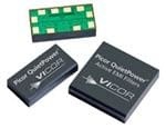
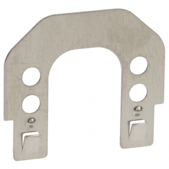
Quiet-Power® QPI-12 7 A VI Chip® EMI Filter SiP Product Description Features The QPI-12EMI filter is specifically designed to attenuate • 45 dB CM attenuation at 1 MHz (50 Ω) conducted common-mode (CM) and differential-mode (DM) • 75 dB DM attenuation at 1 MHz (50 Ω) noise of Vicor’s VI Chip® products, such as the PRM®, VTM® • 80 Vdc (max input) and BCM® converters, to comply with the CISPR22 standard • 100 Vdc surge 100 ms requirements for conducted noise measurements. The filter is designed to operate up to 80 Vdc, 100 Vdc surge, and supports • 1,500 Vdc hipot hold off to shield plane 7 A loads up to 85°C (TA) without de-rating. • 7 A rating Designed for the telecom bus range, the VI Chip EMI filter • 12.9 x 25.3 x 5.0 mm, lidded SiP (System-in-Package) supports the PICMG® 3.0 specification for filtering system • 12.4 x 24.9 x 4.2 mm, open-frame boards to the EN55022 Class B limits. • Low profile LGA package • -40° to +125°C PCB temperature (see Figure 6) • Efficiency >99% • TÜV Certified Applications • VI Chip input EMI filter Figure 1— QPI-12LZ (~1/2 in2area) • Telecom and ATCA boards Typical Applications BUS+ CIN L BUS+ QPI+ IN+ OUT+ IN+ OUT+ CB1 + + LOAD PRM VTM Optional Chassis Connection BUS- QPI- IN- OUT- IN- OUT- BUS- Shield CY1 CY2 CY3 CY4 Chassis/Shield Shield Plane Figure 2— Typical QPI-12 application schematic with Vicor’s PRM and VTM modules.[a] BUS+ CIN BUS+ QPI+ IN+ OUT+ CB1 + + LOAD BCM Optional Chassis Connection BUS- QPI- IN- OUT- BUS- Shield CY1 CY2 CY3 CY4 Chassis/Shield Shield Plane Figure 3— Typical QPI-12 application schematic with Vicor’s BCM module.[a] [a]CB1 capacitor, referenced in all schematics, is a 47 uF electrolytic; United Chemi-Con EMVE101ARA470MKE0S or equivalent. CY1 to CY4, referenced in all schematics, are 4.7 nF hi-voltage safety capacitors; Vishay VY1472M63Y5UQ63V0 or equivalent. Quiet-Power® Rev 2.3 vicorpower.com Page 1of 13 7/2014 800 927.9474
QPI-12 Order Information Part Number Description QPI-12LZ[b] QPI-12 LGA package, RoHS compliant QPI-12LZ-01 QPI-12 LGA package, RoHS compliant, open-frame package Evaluation Board Also Available QPI-12-CB1 A QPI-12LZ mounted on a carrier board that can hold either a stand-alone BCM or a paired PRM/VTM eval board available from Vicor. Absolute Maximum Ratings Exceeding these parameters may result in permanent damage to the product. Name Rating Input voltage, BUS+ to BUS-, continuous -80 to 80 Vdc Input voltage, BUS+ to BUS-, 100 ms transient -100 to 100 Vdc BUS+/ BUS- to Shield pads, hipot -1500 to 1500 Vdc Input to output current, continuous @ 25°C (TA) 7 Adc Power dissipation, @ 85°C (TA), 7 A[c] 1.85 W Operating temperature - TA -40 to 125 °C Thermal resistance[c]- R J-A, using PCB layout in Figure 25 30°C/W θ Thermal resistance[c]- R J-PCB 18°C/W θ Storage temperature, JEDEC Standard J-STD-033B -55 to 125°C Reflow temperature, 20 s exposure 245°C ESD, Human Body Model (HBM) -2000 to 2000 V Electrical Characteristics Parameter limits apply over the operating temp. range, unless otherwise noted. Parameter Conditions Min Typ Max Unit BUS+ to BUS-, input range Measured at 7 A, 85°C ambient temperature[c] 80 Vdc BUS+ to QPI+, voltage drop Measured at 7 A, 85°C ambient temperature[c] 130 mVdc BUS- to QPI-, voltage drop Measured at 7 A, 85°C ambient temperature[c] 130 mVdc Common-mode attenuation VBUS= 48 V, frequency = 1.0 MHz, line impedance = 50 Ω 45 dB Differential-mode attenuation VBUS= 48 V, frequency = 1.0 MHz, line impedance = 50 Ω 75 dB Input bias current at 50 V Input current from BUS+ to BUS- 10 uA [b]QPI-11LZ is a non-hermetically sealed package. Please read the “Post Solder Cleaning” section on Page 11. [c]See Figure 6 for the current de-rating curve. Quiet-Power® Rev 2.3 vicorpower.com Page 2of 13 7/2014 800 927.9474
QPI-12 Pad Descriptions Pin Name Name Description 8, 9 BUS+ Positive bus potential 1, 10 BUS- Negative bus potential 6, 7 QPI+ Positive input to the converter 4, 5 QPI- Negative input to the converter 2, 3 Shield Shield connects to the system chassis or to a safety ground BUS+ QPI+ 8 7 BUS+ 9 6 QPI+ BUS– 10 5 QPI– 1 2 3 4 BUS– Shield Shield QPI– LGA Pattern (Top View) Quiet-Power® Rev 2.3 vicorpower.com Page 3of 13 7/2014 800 927.9474
QPI-12 Applications Information EMI Sources Many of the components in today’s power conversion modules are The differential-mode EMI is typically larger in magnitude than common- sources of high-frequency EMI noise generation. Diodes, high-frequency mode, since common-mode is created by the physical imbalances in the switching devices, transformers and inductors, and circuit layouts passing differential loop path. Reducing differential EMI will cause a reduction in high dv/dt or di/dt signals are all potential sources of EMI. common-mode EMI. EMI is propagated either by radiated or conductive means. Radiated EMI can be sourced from these components as well as by circuit loops that act EMI Filtering like antennas and broadcast the noise signals to neighboring circuit paths. The basic premise of filtering EMI is to insert a high-impedance, at the This also means that these loops can act as receivers of a broadcasted EMI’s base frequency, in both the differential and common-mode paths signal. This radiated EMI noise can be reduced by proper circuit layout as it returns to the power source. and by shielding potential sources of EMI transmission. Passive filters use common-mode chokes and “Y” capacitors to filter out There are two basic forms of conducted EMI that typically need to be common-mode EMI. These chokes are designed to present a high- filtered; namely common-mode (CM) and differential-mode (DM) EMI. impedance at the EMI frequency in series with the return path, and a low Differential-mode resides in the normal power loop of a power source impedance path to the earth signal via the “Y” caps. This network will and its load; where the signal travels from the source to the load and force the EMI signals to re-circulate within a confined area and not to then returns to the source. Common-mode is a signal that travels through propagate to the outside world. Often two common-mode networks are both leads of the source and is returned to earth via parasitic pathways, required to filter EMI within the frequency span required to pass the either capacitively or inductively coupled. EN55022 Class B limits. Figure 10 to Figure 17 are the resulting EMI plots of the total noise, both The other component of the passive filter is the differential LC network. common and differential mode, of Vicor’s PRM/VTM and BCM®evaluation Again, the inductor is chosen such that it will present a high-impedance modules, under various loads, after filtering by the QPI-12LZ. The red and in the differential EMI loop at the EMI’s base frequency. The differential blue traces represent the positive and negative branches of total noise, as capacitor will then shunt the EMI back to its source. The QPI-12 was measured using an industry standard LISN setup, shown in Figures 4 specifically designed to work with higher switching frequency converters and 5. The PRM®and VTM®evaluation boards are mounted to a Picor® like Vicor’s VI Chip®products; PRM, VTM and BCM modules; as well as QPI-12-CB1 board for testing. The QPI-12CB1 carrier is designed to their newer VI Brick™ product series. accept both the PRM/VTM combination of evaluation boards, as well as the stand-alone BCM evaluation board. Figure 4— Open-frame EMI test setup using the QPI-12-CB1 carrier board with VI Chip evaluation boards. Quiet-Power® Rev 2.3 vicorpower.com Page 4of 13 7/2014 800 927.9474
QPI-12 Figure 5— Baseplate EMI test setup using the QPI-12-CB1 carrier board with VI Chip evaluation boards. EMI Management Figure 5 shows the baseplate topology of recirculating “Y” caps. Here, The more effectively EMI is managed at the source, namely the power CY5 to CY10 are connected to each power node of the PRM and VTM, converter, the less EMI attenuation the filter will have to do. The addition and then are commoned together on a copper shield plane created under of “Y” capacitors to the input and output power nodes of the converter the converter. The addition of the copper shield plane helps in the will help to limit the amount of EMI that tries to propagate to the input containment of the radiated EMI, converting it back to conducted EMI source. and shunting it back to its source. There are two basic topologies for the connection of the recirculating “Y” Both of these topologies work well with the PRM/VTM combination capacitors. In Figure 4 the open-frame topology is shown in Picor’s EMI shown above in attenuating noise levels well below Class B EMI limits. test setup. The “Y” capacitors (CY1 to CY4) recirculate the EMI signals between the positive input and output, and the negative input and output of the power conversion stage. Current De-Rating— Mounted to QPI-12-CB1 Evaluation Board Figure 6— Current de-rating over ambient temperature range. Quiet-Power® Rev 2.3 vicorpower.com Page 5of 13 7/2014 800 927.9474
QPI-12 QPI Insertion Loss Measurements [I ] Equation 1.— Insertion Loss = 20 *log * IINA INB Figure 7— Attenuation curves into a 50 Ω line impedance, bias from a 48 V bus. QPI Insertion Loss Test Circuits IPROBE BUS IN BUS+ QPI+ LISN 47uF CSIG INA LOAD Chassis SIG INB VBUS BUS- QPI- SIG Shield 50Ω BUS IN LISN IPROBE Chassis SIG Figure 8— Test set up to measure differential-mode EMI currents in Figure 7. BUS IN BUS+ QPI+ IPROBE LOAD LISN 47uF Chassis SIG VBUS CSIG INA BUS- QPI- Shield INB BUS IN SIG LISN 50Ω IPROBE Chassis SIG Figure 9— Test set up to measure common-mode EMI currents in Figure 7. Quiet-Power® Rev 2.3 vicorpower.com Page 6of 13 7/2014 800 927.9474
QPI-12 Attenuation Plots— QPI-12 with PRM P048F048T24AL-CB and various VTM modules, connected in baseplate configuration, as shown in Figure 4. Figure 10— VTM V048F030T070-CB with 160 W load. Figure 11— VTM V048F120T025-CB with 180 W load. Figure 12— VTM V048F240T012-CB with 172 W output load. Figure 13— VTM V048F480T006-CB with 153 W load. Quiet-Power® Rev 2.3 vicorpower.com Page 7of 13 7/2014 800 927.9474
QPI-12 Attenuation Plots— QPI-12 with various BCM modules, connected in open frame configuration, as shown in Figure 18. Figure 14— BCM B048F030T21-EB with 160 W load. Figure 15— BCM B048F120T30-EB with 180 W load. Figure 16— BCM B048F240T30-EB with 172 W load. Figure 17— BCM B048F480T30-EB with 152 W load. The red and blue traces in Figure 10 through Figure 17 are the measurements of total EMI, in both the positive and negative branches. The test setups shown in Figure 4 and Figure 5 are representative of measuring the positive branch of the total EMI for the unit under test. Quiet-Power® Rev 2.3 vicorpower.com Page 8of 13 7/2014 800 927.9474
QPI-12 Converter Output Grounding— Recommended configurations CY1 4.7nF BUS+ BUS+ QPI+ IN+ OUT+ CB1 + CIN + LOAD BCM Optional Chassis Connection BUS- QPI- IN- OUT- Shield BUS- CY2 Chassis/Shield 4.7nF Figure 18— BCM converter in open-frame configuration with the output connected to chassis/earth. CY1 4.7nF CY2 4.7nF BUS+ L BUS+ QPI+ IN+ OUT+ IN+ OUT+ CB1 + CIN + LOAD 47uF PRM VTM Optional Chassis Connection BUS- QPI- IN- OUT- IN- OUT- Shield BUS- CY3 CY2 Chassis/Shield 4.7nF Figure 19— PRM/VTM in open-frame configuration with the output connected to the chassis/earth. When using the QPI-12 with a Vicor PRM/VTM or BCM, in a power system that requires the converter’s output to be connected to chassis/earth, Picor recommends using the open-frame configuration of “Y” capacitors, shown in Figure 18, to re-circulate EMI currents. A base-plate configuration could also be used with a slight decrease in EMI attenuation, but with peaks well below class B limits. The plot in Figure 20 is of a B048F120T30, with a 125W load, with the output ground connected to the chassis. When using the open-frame configuration of “Y” caps, the EMI shield plane is not used by the “Y” capacitors for recirculating EMI currents. This configuration would also be recommended for a QPI-12 with a PRM/VTM pair, configured as shown in Figure 2. The QPI-12 is not designed to be used in parallel with another QPI-12 to achieve a higher current rating, but it can be used multiple times within a system design. Figure 20 — Total noise plot of BCM with its output return connected to chassis, as shown in Figure 18, 125 W load. Quiet-Power® Rev 2.3 vicorpower.com Page 9of 13 7/2014 800 927.9474
QPI-12 Mechanical Package Drawings 0.006" [0.15mm] max. 0.006" [0.15mm] max. QPI-12LZ 0.508" [12.903 mm] U.S. and Foreign Patents/Patents Pending Lot # Date Code Pin 1 indicator 0.996" [25.298 mm] 0.196" [4.978 mm] Figure 21— Lidded package dimensions, tolerance of ±0.004” 0.006" [0.15mm] max. 00..000066"" [[00..1155mmmm]] mmaaxx.. 0.489" [12.421 mm] 12LZ-01 Pin 1 0.330 [8.382 mm] 0.979" [24.867 mm] 0.164" [4.166 mm] Figure 22— Open open-frame package dimensions, tolerance of ±0.004”. Pick and place from label center. Datum Units QPI-12LZ QPI-12LZ-01 Notes FITS failure/billion hrs. 16 16 FITS based on the BellCore Standard TR-332 MTBF million hrs. 62.5 62.5 MTBFs based on the BellCore Standard TR-332 Weight grams 2.4 2.075 MSL 3 3 Peak Reflow Temperature °C/20 seconds 245 245 IPC/JEDEC J-STD-020D Quiet-Power® Rev 2.3 vicorpower.com Page 10of 13 7/2014 800 927.9474
QPI-12 Pad and Stencil Definitions Figure 23— Bottom view of open-frame (OF) and lidded (LID) products. (All dimensions are in inches) Figure 24— Recommended receptor and stencil patterns. (All dimensions are in inches) Stencil definition is based on a 6 mil stencil thickness, 80% of LGA pad area coverage. LGA package dimensions are for both the open-frame and lidded versions of the QPI-12. Quiet-Power® Rev 2.3 vicorpower.com Page 11of 13 7/2014 800 927.9474
QPI-12 QPI-12 PCB Layout Recommendations Figure 25— 3D view of paralleling planes underneath the QPI-12. The filtering performance of the QPI-12is sensitive to capacitive the recommended PCB layout on a two-layer board. Here, the top coupling between its input and output pins. Parasitic plane layer planes are duplicated on the bottom layer so that there can be capacitance must be kept below one pico-Farad between inputs and no overlapping of input and output planes. This method can be used outputs using the layout shown above and the recommendations for boards of greater layer count. described below to achieve maximum conducted EMI performance. Post Solder Cleaning To avoid capacitive coupling between input and output pins, there Picor’s LZ version QuitePower SiPs are not hermetically sealed and should not be any planes or large traces that run under both input must not be exposed to liquid, including but not limited to cleaning and output pins, such as a ground plane or power plane. For solvents, aqueous washing solutions or pressurized sprays. When example, if there are two signal planes or large traces where one soldering, it is recommended that no-clean flux solder be used, as trace runs under the input pins, and the other under the output pins, this will ensure that potentially corrosive mobile ions will not and both planes overlap in another area, they will cause capacitive remain on, around, or under the module following the soldering coupling between input and output pins. Also, planes that run under process. For applications where the end product must be cleaned both input and outputs pins, but do not cross, can cause capacitive in a liquid solvent, Picor recommends using the QPI-12LZ-01, coupling if they are capacitively by-passed together. Figure 25 shows open-frame version of the EMI filter. Quiet-Power® Rev 2.3 vicorpower.com Page 12of 13 7/2014 800 927.9474
QPI-12 Vicor’s comprehensive line of power solutions includes high density AC-DC and DC-DC modules and accessory components, fully configurable AC-DC and DC-DC power supplies, and complete custom power systems. Information furnished by Vicor is believed to be accurate and reliable. However, no responsibility is assumed by Vicor for its use. Vicor makes no representations or warranties with respect to the accuracy or completeness of the contents of this publication. Vicor reserves the right to make changes to any products, specifications, and product descriptions at any time without notice. Information published by Vicor has been checked and is believed to be accurate at the time it was printed; however, Vicor assumes no responsibility for inaccuracies. Testing and other quality controls are used to the extent Vicor deems necessary to support Vicor’s product warranty. Except where mandated by government requirements, testing of all parameters of each product is not necessarily performed. Specifications are subject to change without notice. Vicor’s Standard Terms and Conditions All sales are subject to Vicor’s Standard Terms and Conditions of Sale, which are available on Vicor’s website or upon request. Product Warranty In Vicor’s standard terms and conditions of sale, Vicor warrants that its products are free from non-conformity to its Standard Specifications (the “Express Limited Warranty”). This warranty is extended only to the original Buyer for the period expiring two (2) years after the date of shipment and is not transferable. UNLESS OTHERWISE EXPRESSLY STATED IN A WRITTEN SALES AGREEMENT SIGNED BY A DULY AUTHORIZED VICOR SIGNATORY, VICOR DISCLAIMS ALL REPRESENTATIONS, LIABILITIES, AND WARRANTIES OF ANY KIND (WHETHER ARISING BY IMPLICATION OR BY OPERATION OF LAW) WITH RESPECT TO THE PRODUCTS, INCLUDING, WITHOUT LIMITATION, ANY WARRANTIES OR REPRESENTATIONS AS TO MERCHANTABILITY, FITNESS FOR PARTICULAR PURPOSE, INFRINGEMENT OF ANY PATENT, COPYRIGHT, OR OTHER INTELLECTUAL PROPERTY RIGHT, OR ANY OTHER MATTER. This warranty does not extend to products subjected to misuse, accident, or improper application, maintenance, or storage. Vicor shall not be liable for collateral or consequential damage. Vicor disclaims any and all liability arising out of the application or use of any product or circuit and assumes no liability for applications assistance or buyer product design. Buyers are responsible for their products and applications using Vicor products and components. Prior to using or distributing any products that include Vicor components, buyers should provide adequate design, testing and operating safeguards. Vicor will repair or replace defective products in accordance with its own best judgment. For service under this warranty, the buyer must contact Vicor to obtain a Return Material Authorization (RMA) number and shipping instructions. Products returned without prior authorization will be returned to the buyer. The buyer will pay all charges incurred in returning the product to the factory. Vicor will pay all reshipment charges if the product was defective within the terms of this warranty. Life Support Policy VICOR’S PRODUCTS ARE NOT AUTHORIZED FOR USE AS CRITICAL COMPONENTS IN LIFE SUPPORT DEVICES OR SYSTEMS WITHOUT THE EXPRESS PRIOR WRITTEN APPROVAL OF THE CHIEF EXECUTIVE OFFICER AND GENERAL COUNSEL OF VICOR CORPORATION. As used herein, life support devices or systems are devices which (a) are intended for surgical implant into the body, or (b) support or sustain life and whose failure to perform when properly used in accordance with instructions for use provided in the labeling can be reasonably expected to result in a significant injury to the user. A critical component is any component in a life support device or system whose failure to perform can be reasonably expected to cause the failure of the life support device or system or to affect its safety or effectiveness. Per Vicor Terms and Conditions of Sale, the user of Vicor products and components in life support applications assumes all risks of such use and indemnifies Vicor against all liability and damages. Intellectual Property Notice Vicor and its subsidiaries own Intellectual Property (including issued U.S. and Foreign Patents and pending patent applications) relating to the products described in this data sheet. No license, whether express, implied, or arising by estoppel or otherwise, to any intellectual property rights is granted by this document. Interested parties should contact Vicor's Intellectual Property Department. The products described on this data sheet are protected by the following U.S. Patents Number: 6,898,092 Vicor Corporation Picor Corporation 25 Frontage Road 51 Industrial Drive Andover, MA 01810 USA North Smithfield, RI 02896 USA email Customer Service: custserv@vicorpower.com Technical Support: apps@vicorpower.com Quiet-Power® Rev 2.3 vicorpower.com Page 13of 13 7/2014 800 927.9474
Mouser Electronics Authorized Distributor Click to View Pricing, Inventory, Delivery & Lifecycle Information: V icor: QPI-12LZ QPI-12-CB1 QPI-12LZ-01