ICGOO在线商城 > 连接器,互连器件 > 背板连接器 - 专用 > QLC260P
 Datasheet下载
- 型号: QLC260P
- 制造商: ITT CANNON
- 库位|库存: xxxx|xxxx
- 要求:
| 数量阶梯 | 香港交货 | 国内含税 |
| +xxxx | $xxxx | ¥xxxx |
查看当月历史价格
查看今年历史价格
QLC260P产品简介:
ICGOO电子元器件商城为您提供QLC260P由ITT CANNON设计生产,在icgoo商城现货销售,并且可以通过原厂、代理商等渠道进行代购。 QLC260P价格参考¥526.85-¥673.37。ITT CANNONQLC260P封装/规格:背板连接器 - 专用, 。您可以下载QLC260P参考资料、Datasheet数据手册功能说明书,资料中有QLC260P 详细功能的应用电路图电压和使用方法及教程。
ITT Cannon, LLC是一家专业生产高可靠性连接器的公司,其QLC260P型号属于背板连接器中的专用型产品。该连接器主要应用于航空航天、军事装备和高性能计算等领域。

QLC260P具备优良的电气性能和机械稳定性,适用于需要高密度信号传输和抗干扰能力的复杂环境。例如,在军用通信设备中,它可用于实现模块之间的高速互联;在航空电子系统中,则可支持雷达、导航与数据处理系统的稳定连接。

此外,该型号也适合用于工业自动化控制系统或测试测量设备中,满足对可靠性和耐用性有较高要求的应用场景。整体而言,QLC260P是一款面向高端市场的背板连接器,专为严苛环境下工作的关键系统而设计。
| 参数 | 数值 |
| 产品目录 | |
| 描述 | CONN RECEP M 260POS SLDR ST |
| 产品分类 | |
| 品牌 | ITT Cannon, LLC |
| 数据手册 | |
| 产品图片 |
|
| 产品型号 | QLC260P |
| rohs | 无铅 / 符合限制有害物质指令(RoHS)规范要求 |
| 产品系列 | QLC |
| 其它名称 | 1003-2399 |
| 列数 | - |
| 加载的针脚数 | 全部 |
| 包装 | 散装 |
| 安装类型 | - |
| 工作温度 | -55°C ~ 85°C |
| 排数 | 4 |
| 材料可燃性等级 | - |
| 标准包装 | 40 |
| 特性 | 屏蔽 |
| 特色产品 | http://www.digikey.cn/product-highlights/zh/itt-qlc-quad-lock-connector-series/51710 |
| 相关产品 | /product-detail/zh/127059-0069/1003-2401-ND/4571125 |
| 端接 | |
| 触头布局(典型) | - |
| 触头镀层 | 金 |
| 触头镀层厚度 | 40µin(1.02µm) |
| 连接器样式 | - |
| 连接器用途 | 子卡 |
| 连接器类型 | 插头,公引脚 |
| 针脚数 | 260 |
| 间距 | 0.031"(0.80mm) |
| 颜色 | - |
| 额定电压 | - |
| 额定电流 | 0.5A |


- 商务部:美国ITC正式对集成电路等产品启动337调查
- 曝三星4nm工艺存在良率问题 高通将骁龙8 Gen1或转产台积电
- 太阳诱电将投资9.5亿元在常州建新厂生产MLCC 预计2023年完工
- 英特尔发布欧洲新工厂建设计划 深化IDM 2.0 战略
- 台积电先进制程称霸业界 有大客户加持明年业绩稳了
- 达到5530亿美元!SIA预计今年全球半导体销售额将创下新高
- 英特尔拟将自动驾驶子公司Mobileye上市 估值或超500亿美元
- 三星加码芯片和SET,合并消费电子和移动部门,撤换高东真等 CEO
- 三星电子宣布重大人事变动 还合并消费电子和移动部门
- 海关总署:前11个月进口集成电路产品价值2.52万亿元 增长14.8%

PDF Datasheet 数据手册内容提取
DL Series ZIF connectors
Cannon, VEAM, BIW A Historical Achievement of Technology Leadership Defining and Championing Innovation Showcasing a portfolio of creativity, ITT’s “Engineered For Life” execution embraces products which have become ubiquitous in a broad collection of markets including: Military/Aerospace, Civil Aircraft, Industrial Instrumentation, Medical, Oil & Gas, Energy, Transportation, Telecom/Handset, Computer, Consumer, and Automotive. ITT’s rich interconnect history embraces contributions to both technological breakthroughs and social movements. With one of the industry’s broadest product offerings, ITT’s interconnect products have supported: • Every Free World space mission, bringing the universe to our doorstep. • Motion picture, radio, and television equipment, serving laughter and entertainment to millions. • Commercial and military communications systems, linking the voices of the world. • Computerized tools, reshaping the information highway. • Aircraft, rapid transit, and automobiles, mobilizing our expanding society. • Oil and natural gas production, powering the world’s economies. • Agricultural equipment, attacking the roots of world hunger. www.ittcannon.com
ITT Cannon ITT Cannon is a brand of the multi-national ITT give ITT the most optimized global manufacturing Corporation. Our connector portfolio remains the most footprint in the interconnect industry. extensive in the industry offering the most reliable and cost effective range of interconnect solutions. These The Custom Difference innovations have enabled ITT to provide products and technologies to such markets as: As the industry leader in harsh environment • Automotive interconnect applications, ITT’s world class engineering • Computer/Consumer teams will work directly with our customers to design • Industrial/Instrumentation and develop cost effective solutions for their applications. • Military/Aerospace In many cases we may modify one of our standard • Oil Fields designs to ensure a highly reliable solution where timing • Telecom/Handset is critical. Yet, in those cases where a complete custom • Transportation interconnect solution is required, ITT will work with our customer’s Engineers to design an interconnect When you specify a Cannon, VEAM or BIW connector, solution which will be cost effective yet highly reliable. you can rely on a product designed, developed, and As professional consultants, our Engineering teams will manufactured to the highest quality and reliability provide a thorough systems and mechanical analysis standards. This tradition of excellence is based on ITT’s of any proposed solution. These analyses provide our corporate culture of operating its businesses under the customers with sophisticated electrical signal and principles of Six Sigma. At ITT, Six Sigma is not just a mechanical characterizations to determine the best quality philosophy but a complete corporate culture that solution for their application. drives the entire business. Our Value Based Management and Value Based Product Development systems are two RoHS Compliance Information cornerstones that allow for the development of both leadership and product engineering principles, ensuring ITT has implemented a strict parts control plan for the correct industry leading products are developed to all ITT electronics plants worldwide that allows the the accepted market driven lead times. These principles Cannon, VEAM, and BIW connector product portfolios have allowed ITT to become the market leader in all of to meet the requirements of European Union Directive our business portfolios. 2002/95/EC better know as the Reduction of Hazardous Substances initiative. As appropriate, specific Six Sigma Manufacturing Cannon, VEAM, and BIW products may be ordered with an R prefix number which insures our customers ITT operates manufacturing facilities in the United States, will receive RoHS compliant parts for their commercial Germany, Italy, Mexico, China, Japan and the UK, all of electronics applications and equipment. Since most which have particular product area strengths allowing RoHS hazardous substances center around specific ITT to offer a truly global footprint to our customers. metal plating and lead solder coatings, ITT’s products Our facilities are world class and accommodate full for RoHS compliance are available in the following vertical integration utilizing the latest manufacturing plating finishes: black zincelectroless nickel, stainless technologies including: automated and robotic machining steel, Anodize over aluminum and Gold plating. It should centers, Super Market manufacturing cells, Kanban pull be noted that gold plating would be recommended systems, and automated electrical, mechanical, and as the replacement for tin-lead solder when ordering optical test and inspection equipment. The combination board mount connectors. of our manufacturing strength and our advanced manufacturing facilities allows ITT to offer products at market driven prices. Our capabilities, especially in robotics, computerized precision tooling, Kaizen Project Management, Six Sigma tools, and testing,
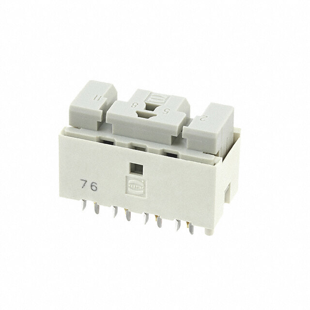
Cannon ZIF Connectors Table of Contents DL Introduction ................. 10 Product Specifications........... 11 • Plastic Body How to Order ................. 12 • 60, 96, 156, or 260 Contact Cavities Layout Information...........13-16 • Single Hand Actuation • Crimp or Square Post Contacts DLM Introduction ................. 21 Product Specifications........... 22 • Metal Body How to Order ................. 23 • EMI/RFI Shielding Layout Information...........24-28 • 60, 96, 156, 260 or 360 Contact Cavities • Single Hand Actuation • Crimp, Square Post or PC/RC Contacts DLP Introduction ................. 29 Product Specifications........... 29 • Metal Body How to Order ................. 30 • EMI/RFI Shielding Layout Information...........31-32 • Modular Landed Contact System (DLP-272- 34 Contacts/Module DLP-408 - 68 Contacts/Module) • Single Hand Actuation www.ittcannon.com 4
Cannon ZIF Connectors Table of Contents QLC Introduction ................. 33 • Metal Body Product Specifications......... 33 • EMI / RFI Shielding Layout Information ........... 34 • 260 Contacts • Small form factor. For portable equipment Accessories Introduction ................. 35 Selection Guide................ 35 • Cannon offers a large selection of accessories to meet a variety of Junction Shells, Plastic........... 36 application requirements Backshells, Metal............... 38 • Allows customization using standard Actuating Handles.............. 39 components Protective Covering............. 40 Polarizing Posts................ 41 Shells (EMI/RFI) ................ 42 Contacts Introduction ................. 43 Buss Contacts ................. 44 • Crimp and Buss contacts are available loose or reeled Crimp Contacts-Loose / Reeled .... 45 • Accommodates wire sizes #42-#18AWG • Customer installed. Field installable/removable Tools and Assembly Introduction ................. 46 • Cannon offers hand crimp tooling for Hand Crimp Tools.............. 46 low volume applications Extraction Tools................ 47 • Contact extraction tools Assembly Instructions.........48-50 • Automatic tooling can be leased for Lease Automatic Tooling.......51-52 large volume applications PCB Hole Pattern and Pad Layout . . . . . . . . . . . . . . . . . . . . . . . . . . . . . . . . . . . . . . . . . . .53-60 Panel Cutouts . . . . . . . . . . . . . . . . . . . . . . . . . . . . . . . . . . . . . . . . . . . . . . . . . . . . . . . . . .61-67 Contact Cavity Arrangements . . . . . . . . . . . . . . . . . . . . . . . . . . . . . . . . . . . . . . . . . . . . . .64-66 www.ittcannon.com 5
Cannon ZIF Connectors Product Overview Guide DL DLM DLP 136 - 272 DLP 408 QLC Type Plug & Receptacle Plug & Receptacle Plug & Receptacle Plug & Receptacle Plug & Receptacle Body Plastic Metal Metal Metal Metal Body Material Thermoplastic Aluminum Aluminum Zinc Alloy Zinc Available 60; 96; 156; and 260 60; 96; 156 260 and 136, 204 and 272 408 signal 260 signal Layouts signal 360 signal signal Crimp Contacts yes yes - - - Square Post yes yes - - - Contacts PC/RC Contacts - yes - - - Pressfit Contacts yes (1) yes (2) no yes no Current 5 A max. (3) / 4 A max. 5 A max. (3) 0,5 A max. 0,3 A max 0,5A max Rating (4) 100 milliohms max Contact 30 milliohms max. 30 milliohms max. 15 milliohms max. 15 milliohms max. (includes bulk resis- Resistance (Initial) (Initial) tance) 20 milliohms max. (5) 20 milliohms max. (5) 30 milliohmms max. (4) 20 or 50μ inches gold 20 or 50μ inches gold Gold plated Gold plated 40μ inch gold plated Contact Material plated plated copper Alloy copper Alloy copper alloy copper alloy copper alloy Operating -55°C to 105°C -55°C to 105°C -55°C to 85°C -55°C to 85°C -55°C to 85°C temperature RoHS compliant yes yes yes yes yes Factory Solder to PCB Through Solder to PCB Through Solder to PCB Through Solder to PCB Press-fit terminated Hole Hole Hole through hole Mating cycles 10.000 min. 10.000 min. 10,000 max 10,000 max 20,000 max EMI/RFI shielding - yes yes yes yes Accessories See Pages 40-47 Actuating handles yes yes yes yes yes Protective Cover yes yes - - - (Rubber) (6) Protective Cover yes yes yes - - (Plastic) (7) Metals Shell for EMI/ yes (5) - - - - RFI shielding Plastic Junction Shell yes yes - - - Cable Clamps yes yes - - - Metals Backshell yes yes - - - Polarizing Posts yes yes - - - Page number 10-16 21-28 34-36 37 38-39 Notes: (1) DL5 only (2) DLM5 only (3) Crimp or Square Post Contacts (4) PC/RC contact (5) Specification for Crimp Contacts smaller than 28 AWG www.ittcannon.com 6
Cannon ZIF Connectors Product Features The mechanical function of the new DLP ZIF connector A quarter turn of knob (shaft) mates all the contact at once by the function of cam and bearing. Bearing Plug side PCB Cam shaft Contact Our DLP connector uses our landed contact system. Modules of 34 or 68 contacts each are populated in to the receptacle to the customer’s requirements. These contacts are positioned to land on pads that are designed into the customer supplied PCB and mounted to the plug connector housing. When mated, the contacts do not touch the pads on the plug PCB. Once the handle is rotated and locked, the shape of the receptacle contact generates a slight wipe on the plug PCB pads. Dimensions shown in mm (inch) Specifications and dimensions subject to change www.ittcannon.com 7
Cannon ZIF Connectors Product Features The long life and rapid mating are achieved through the use of our Zero Insertion Force design. Contact in the plug and receptacle do not touch each other while the connector halves are being engaged. Step 1: The plug is placed over the receptacle. Step 2: A “quarter turn” of an actuating shaft mates all contacts at once. Step 3: The same “quarter turn” also physically locks the connector halves together. Connector engagement force is zero, and the only wear on the contacts occurs as they are pressed together and lightly wiped past each other during the camming and locking operation. Dimensions shown in mm (inch) Specifications and dimensions subject to change www.ittcannon.com 8
Cannon ZIF Connectors Typical Applications Medical Test & Instrument • Ultrasound Diagnostic • Avionics • Patient Monitoring • Automated Test Equipment • Hospital Equipment • Computer and Peripheral Equipment • MRI (Non-Magnetic) • Semiconductor • Portable Equipment (Imaging) Commercial / Industrial Entertainment Manufacturing • Recording Studio Equipment • Stage Lighting and Sound • Automation • Broadcasting Equipment • Robotics • Electrical Controls Transportation Telecommunications • Locomotive Systems • Systems Interconnect • Automotive Electronics • Manufacturing Test Equipment • Aircraft Simulators • Switching Systems Dimensions shown in mm (inch) Specifications and dimensions subject to change www.ittcannon.com 9
Cannon ZIF Connectors DL - Plastic Body The Cannon DL Series of Zero Insertion Force (ZIF) connectors fill the need in the medical, commercial / indus- trial, computer, and peripheral equipment market places for low-cost, high performance, multiple-wire power and signal connectors. DL connectors feature: a minimum rated life of 10,000 complete mating and unmating cycles with no performance loss; can be mated and unmated in less than two seconds even with as many as 624 contacts; and they cost less (often as much as 25% less) per mated line than singular high-density rack-and-panel connectors. Simple. Effective. Reliable. Durable Combining their special design with commercial-grade materials and low cost crimp, PCB, and wrappable hermaph- roditic contacts, that may be hand or machine terminated, makes the DL Series of ZIF connectors the finest low-cost- per-mated-line I/0 connectors available today. Derating Curves DL1 DL2 DL3 The ambient temperature curves shown represent the rated current carrying capacity of the Cannon DL1/2/3/4, electrical connectors, derated to 80%of the values recorded during the methods specified by International Electro-Technical Commission Document 48 (1975). Current was applied to the total connector (all contacts) in one-half ampere increments and maintained at each current level until thermal stability was achieved. A thermocouple inserted into the “hottest area” of each connector then measured the connector temperature at the same time that an ambient temperature reading was taken. The difference between the two measured values is the heat rise or self-heating created solely by the current flow, and this temperature rise for the current level was deducted from the insulator material rated temperature. These values were then derated to 80% to obtain the curves shown. Dimensions shown in mm (inch) Specifications and dimensions subject to change www.ittcannon.com 10
Cannon ZIF Connectors DL - Plastic Body Standard Materials and Finishes DL Housing: Glass Filled Thermoplastic, UL 94V-1 rated, Color: Black Crimp Contacts and - Copper alloy, 20 or 50 microinches gold over 50 microinches nickel in mated area, Square Post Contacts: gold flash on balance Actuating Camshaft: Stainless steel, Passivated Insulator Retainer (Plug Only) Stainless steel, Passivated Electrical Data No. of Contacts: 60, 96, 156, and 260 signal Wire Size: #18 AWG through #42 AWG Contact Termination: - Crimp - Square Post - Wrap Post - Buss - Pressfit Mechanical Data Actuation: Single Hand Coupling: Rotating latch Polarization: Polarizing Posts Contact Spacing: 2,54 (0.100) Square Grid Shell Styles: Plug and Receptacle Performance Data Current Rating: 5 A max - Crimp/Square Post/PCB contact 10 A, 20 A, 30 A, 40 A, 50 A, 60 A max - Buss contact Dielectric Withstanding Voltage: 1200 VAC RMS - Crimp/Square Post Contact Operating Temperature: -55°C to 105°C (DL/DLM/DLD) Insulation Resistance: 5000 Megaohms minimum Durability: 10,000 Cycles minimum Contact Resistance: 15 mΩ max. - Crimp/Square Post Contact 20 mΩ max. - Crimp #32 AWG - #30 AWG Contact Insulation Resistance: 5000 MΩ min. Wire Accommodation: #42 AWG - #18 AWG Contact Retention: 8 lb (35.585 N) minimum Dimensions shown in mm (inch) Specifications and dimensions subject to change www.ittcannon.com 11
Cannon ZIF Connectors DL - Plastic Body How to Order DL 1 - 156 P W6 SERIES DL: Thermo filled thermoplastic SIZE - CONTACT ARRANGEMENT 1 - 156 2 - 96 3 - 60 5 - 260 TYPE P - Plug R - Receptacle CONTACT TYPE No letter - Crimp #18 thru #42 AWG TO BE ORDERED SEPARATELY AND INSTALLED BY CUSTOMER W4 - Wrap Post 15,37 (0.605), 20 inches Gold W4A - Wrap Post 15,37 (0.605), 50 inches Gold, Plug only W4B - Wrap Post 15,37 (0.605), 50 inches Gold, Receptacle only W6 - Square Post 7,11 (0.280), 20 inches Gold W6A - Square Post 7,11 (0.280), 50 inches Gold, Plug only W6B - Square Post 7,11 (0.280), 50 inches Gold, Receptacle only W9A - Square Post 3,18 (0.125), 50 inches Gold, Plug only W9B - Square Post 3,18 (0.125), 50 inches Gold, Receptacle only F - Pressfit, 20 inches Gold, DL5 Receptacle only Dimensions shown in mm (inch) Specifications and dimensions subject to change www.ittcannon.com 12
Cannon ZIF Connectors DL - Plastic Body - Crimp Contacts Plug • Order Actuating Handle Kit sold separately, see page 44. • Crimp Contacts are to be ordered separately and to be installed by customer, see pages 48-50. • For contact cavity arrangements see pages 69-70. • For panel cutout and mounting hole pattern, see page 66. • For PC hole pattern, see pages 59-61. A 7,92 (.312) CAMSHAFT TURNING DIRECTION B C D (2.93,1100) G (.62,5305) H 4X Ø 3,03 (.119) E F Description A B C D E F G H DL3-60P 65,80 57,91 50,55 11,89 24,90 39,19 24,90 49,02 (2.592) (2.280) (1.992) (0.466) (0.981) (1.543) (0.981) (1.931) DL2-96P 65,80 57,91 50,60 19,38 28,12 39,19 24,05 50,60 (2.592) (2.280) (1.994) (.763) (1.108) (1.543) (0.947) (1.994) DL1-156P 108,00 100,03 92,26 16,26 24,90 54,81 20,10 92,10 (4.255) (3.938) (3.631) (0.640) (0.980) (2.158) (0.792) (3.626) DL5-260P 108,00 100,03 92,26 26,00 35,00 54.26 30,30 92,10 (4.255) (3.938) (3.631) (1.024) (1.378) (2.136) (1.193) (3.626) Receptacle • Crimp Contacts are to be ordered separately and to be installed by customer, see pages 48-50. • For contact cavity arrangements see pages 69-70. • For panel cutout and mounting hole pattern, see page 66. • For PC hole pattern, see pages 59-61. A B D 7,75 (.305) C G 4X Ø 3,03 (.119) E 20,32 (.800) H 6,35 (.250) Description A B C D E G H DL3-60R 65,80 57,91 50,50 11,89 24,90 19,18 49,02 (2.592) (2.280) (1.988) (0.468) (0.981) (0.755) (1.931) DL2-96R 65,80 57,91 50,60 19,38 28,12 24,05 50,60 (2.592) (2.280) (1.994) (.763) (1.108) (0.947) (1.994) DL1-156R 108,00 100,03 92,10 16,26 24,90 20,10 92,10 (4.255) (3.938) (3.622) (0.640) (0.980) (0.792) (3.626) DL5-260R 108,00 100,03 92,10 26,00 35,00 30,30 92,10 (4.255) (3.938) (3.622) (1.024) (1.378) (1.193) (3.626) Notes: Crimp contacts are to be ordered separately and to be installed by customer, see pages 49-50. Dimensions shown in mm (inch) Specifications and dimensions subject to change www.ittcannon.com 13
Cannon ZIF Connectors DL - Plastic Body - Square / Wrap Post Contacts Plug • Order Actuating Handle Kit sold separately, see page 44. • For contact cavity arrangements see pages 69-70. • For panel cutout and mounting hole pattern, see page 66. • For PC hole pattern, see pages 59-61. A 7,92 (.312) B C D 27,75 (1.093) CAMSHAFT L TURNING DIRECTION G I @ 2,54 (.100) = 12,70 (.500) 4X Ø 3,03 (.119) E0,64 (.025) 6,35 (.250) F J @ 2,54 (.100) J @ 2,54 (.100) = 30,48 (1.200) = 30,48 (1.200) H Description A B C D E F G H I J L DL3-60PW4 65,80 57,91 50,55 11,89 24,90 34,54 19,94 49,02 5 4 15,37 D L3-60 PW4A (2.592) (2.280) (1.992) (.468) (.981) (1.360) (.785) (1.931) spaces spaces (.605) DL3-60PW6 65, 80 57,91 50,55 11,89 24,90 34,54 19,94 49,02 5 4 7,11 (2.592) (2.280) (1.992) (.468) (.981) (1.360) (.785) (1.931) spaces spaces (.280) DL3-60PW6A 65,80 57,91 50,55 11,89 24,90 34,54 19,94 49,02 5 4 3,18 DL3-60PW9A (2.592) (2.280) (1.992) (.468) (.981) (1.360) (.785) (1.931) spaces spaces (.125) DL2-96PW4 65,80 57,91 50,60 19,38 28,12 34,54 24,05 50,60 7 6 15,37 D L2-96 PW4A (2.592) (2.280) (1.994) (.763) (1.108) (1.360) (.947) (1.994) spaces spaces (.605) DL2-96PW6 65,80 57,91 50,60 19,38 28,12 34,54 24,05 50,60 7 6 7,11 D L2-96 PW6A (2.592) (2.280) (1.994) (.763) (1.108) (1.360) (.947) (1.994) spaces spaces (.280) 65,80 57,91 50,60 19,38 28,12 34,54 24,05 50,60 7 6 3,18 DL2-96PW9A (2.592) (2.280) (1.994) (.763) (1.108) (1.360) (.0947) (1.994) spaces spaces (.125) DL1-156PW4 108,00 100,03 92,26 16,26 24,90 50,16 20,10 92,10 5 12 15,37 DL1-15 6PW4A (4.255) (3.983) (3.631) (.640) (.981) (1.975) (0.792) (3.626) spaces spaces (.605) DL1-156PW6 108,00 100,03 92,26 16,26 24,90 50,16 20,10 92,10 5 12 7,11 DL1-15 6PW6A (4.255) (3.983) (3.631) (.640) (.981) (1.975) (.792) (3.626) spaces spaces (.380) 108,00 100,03 92,26 16,26 24,90 50,16 20,10 92,10 5 12 3,18 DL1-156PW9A (4.255) (3.983) (3.631) (.640) (.981) (1.975) (.792) (3.626) spaces spaces (.125) DL5-260PW4 108,00 100,03 92,26 26,00 35,00 49,61 30,30 92,10 9 12 15,37 D L5-26 0PW4A (4.255) (3.983) (3.631) (1.024) (1.378) (1.953) (1.193) (3.626) spaces spaces (.604 ) DL5-260PW6 108,00 100,03 92,26 26,00 35,00 49,61 30,30 92,10 9 12 7,11 DL5-26 0PW6A (4.255) (3.983) (3.631) (1.024) (1.378) (1.953) (1.193) (3.626) spaces spaces (.280) 108,00 100,03 92,26 26,00 35,00 49,61 30,30 92,10 9 12 3,18 DL5-260PW9A (4.255) (3.983) (3.631) (1.024) (1.378) (1.953) (1.193) (3.626) spaces spaces (.125) Notes: Front removable 0,64 (0.025) square posts 2,54 (0.100) Centers. 1 space at 2,54 (0.100) Dimensions shown in mm (inch) Specifications and dimensions subject to change www.ittcannon.com 14
Cannon ZIF Connectors DL - Plastic Body - Square / Wrap Post Contacts Receptacle • For contact cavity arrangements see pages 69-70. • For panel cutout and mounting hole pattern, see page 66. • For PC hole pattern, see pages 59-61. A 7,75 (.305) B C D I @ 2,54 (.100) = 12,70 (.500) L G 24,97 (.983) 4X Ø 3,03 (.119) J @ 2,54 (.100) J @ 2,54 (.100) E 0,64 (.025) 6,35 (.250) = 30,48 (1.200) = 30,48 (1.200) H Description A B C D E G H I J L DL3-60RW4 65,80 57,91 50,50 11,89 24,90 19,94 49,02 5 4 15,37 DL3-60 RW4B (2.592) (2.280) (1.988) (.466) (.980) (0.785) (1.931) spaces spaces (.605) DL3-60RW6 65,80 57,91 50,50 11,89 24,90 19,94 49,02 5 4 7,11 DL3-60 RW6B (2.592) (2.280) (1.988) (.466) (1.360) (.785) (1.931) spaces spaces (.280) 65,80 57,91 50,50 11,89 24,90 19,94 49,02 5 4 3,18 DL3-60RW9B (2.592) (2.280) (1.988) (0.466) (1.360) (.785) (1.931) spaces spaces (.125) DL2-96TW4 65,80 57,91 50,60 19,38 28,12 24,05 50,60 7 6 15,37 D L 2 - 9 6 R W 4 B (2.592) (2.280) (1.994) (.763) (1.108) (,947) (1.994) spaces spaces (.605) DL2-96RW6 65,80 57,91 50,60 19,38 28,12 24,05 50,60 7 6 7,11 D L 2 - 9 6 R W 6 B (2.592) (2.280) (1.994) (.763) (1.108) (,947) (1.994) spaces spaces (.280) 65,80 57,91 50,60 19,38 28,12 24,05 50,60 7 6 3,18 DL2-96RW9B (2.592) (2.280) (1.994) (.763) (1.108) (,947) (1.994) spaces spaces (.125) DL1-156RW4 108,00 100,03 92,00 16,26 24,90 20,10 92,10 5 12 15,37 DL1-15 6RW4B (4.255) (3.983) (3.622) (.640) (.980) (.792) (3.626) spaces spaces (.605) DL1-156RW6 108,00 100,03 92,00 16,26 24,90 20,10 92,10 5 12 7,11 DL1-15 6RW6B (4.255) (3.983) (3.622) (.640) (.980) (.792) (3.626) spaces spaces (.380) 108,00 100,03 92,00 16,26 24,90 20,10 92,10 5 12 3,18 DL1-156RW9B (4.255) (3.983) (3.622) (.640) (.980) (.792) (3.626) spaces spaces (.125) DL5-260RW4 108,00 100,03 92,00 26,00 35,00 30,30 92,10 9 12 15,37 DL5-26 0RW4B (4.255) (3.983) (3.622) (1.024) (1.378) (1.193) (3.626) spaces spaces (.604) DL5-260RW6 108,00 100,03 92,00 26,00 35,00 30,30 92,10 9 12 7,11 DL5-26 0RW6B (4.255) (3.983) (3.622) (1.024) (1.378) (1.193) (3.626) spaces spaces (.280) 108,00 100,03 92,00 26,00 35,00 30,30 92,10 9 12 3,18 DL5-260RW9B (4.255) (3.983) (3.622) (1.024) (1.378) (1.193) (3.626) spaces spaces (.125) Notes: Front removable 0,64 (0.025) square posts 2,54 (0.100) Centers. 1 space at 2,54 (0.100) Dimensions shown in mm (inch) Specifications and dimensions subject to change www.ittcannon.com 15
Cannon ZIF Connectors DL5 - Plastic Body - Pressfit Contacts Receptacle only • For contact cavity arrangements see page 70. • For panel cutout and mounting hole pattern, see page 66. • For PC hole pattern, see page 62. Part Number Nomenclature 11987-0008 DL5-260R-F 4.283 3.620 3.343 3.937 Dimensions shown in mm (inch) Specifications and dimensions subject to change www.ittcannon.com 16
CCaannnnoonn ZZIIFF CCoonnnneeccttoorrss DDLLDD -- PPllaassttiicc BBooddyy Cannon has combined Zero Insertion Force (ZIF) technology with remote electrical engagement. The DLD Drawer allows the movement of a drawer or panel to effortlessly mate/unmate the connector halves. As an example: electrical sub-systems can be easily removed for service, interchangability, or portability. By specifying DLD Drawer interconnect systems, your packaging design is simplified as the need for expensive, complicated, and space-consuming manual actuation mechanisms is eliminated. TIght space requirements no longer restrict your use of ZIF con- nectors. The contacts in the DLD Drawer product line do not touch each other while the connector halves are mating. This unique ZIF technology, introduced in the Cannon DL series in the early 1970’s, has time-tested proven reliability and durability. The DLD Drawer’s remote mating feature utilizes the axial thrust of a cam to move and mate the contacts. At the end of the cam travel, the cam ramps on a flat surface thereby negating any uncoupling forces. This rack-and-panel connector is available with crimp or square post contacts, allowing cable, PCB, or flat- flex termination. Standard Materials and Finishes DLD Housing: Glass Filled Thermoplastic, UL 94V-1 rated, Color: Black Crimp Contacts: Copper alloy, 20 or 50 microinches gold over 50 microinches nickel in mated area, gold flash on balance Insulator Retainer (1): Stainless steel, Passivated Actuating Camshaft (2): Stainless steel Spring Mounting Screw (2): Stainless steel, Passivated Electrical Data No. of Contacts: 96 and 156 signal Wire Size: #18 AWG through #42 AWG Contact Termination: Crimp, Square Post, Wrap Post, Buss Mechanical Data Actuation: Sliding Coupling: Guide Cam Polarization: Polarizing Posts Contact Spacing: 2,54 (.100) Square Grid Shell Styles: Plug and Receptacle Performance Data Dielectric Withstanding Voltage: 1200 VAC RMS - Crimp/Square Post Contact Insulation Resistance 5000 Megaohms minimum Durability: 100,000 Cycles minimum Contact Resistance: - 15 milliohms maximum - Crimp/Square Post Contact - 20 milliohms maximum - Crimp #30- #32 AWG contact Contact Retention: 6 lb (35,564 N) minimum Dimensions shown in mm (inch) Dimensions shown in mm (inch) Specifications and dimensions subject to change Specifications and dimensions subject to change www.ittcannon.com www.ittcannon.com 17 17
CCaannnnoonn ZZIIFF CCoonnnneeccttoorrss DDLLDD -- PPllaassttiicc BBooddyy How to Order DLD 1 - 156 P W6A SERIES DLD: Glass filled thermoplastic SIZE - CONTACT ARRANGEMENT 1 - 156 2 - 96 TYPE P - Plug R - Receptacle CONTACT TYPE No letter - Crimp #18 thru #42 AWG TO BE ORDERED SEPARATELY AND INSTALLED BY CUSTOMER W4 - Wrap Post 15,37 (0.605), 20 inches Gold W4A - Wrap Post 15,37 (0.605), 50 inches Gold, Plug only W4B - Wrap Post 15,37 (0.605), 50 inches Gold, Receptacle on ly W6 - Square Post 7,11 (0.280), 20 inches Gold W6A - Square Post 7,11 (0.280), 50 inches Gold, Plug only W6B - Square Post 7,11 (0.280), 50 inches Gold, Receptacle only W9A - Square Post 3,18 (0.125), 50 inches Gold W9B - Square Post 3,18 (0.125), 50 inches Gold, Receptacle only DDimimenensisoionnss sshhoowwnn iinn mmmm ((iinncchh)) SpeciSficpaetcioifnics aatniodn dsi manedn sdioimnse nsusbiojencst stou bcjheacntg teo wwwwww..iittttccaannnnoonn..ccoomm 1188
CCaannnnoonn ZZIIFF CCoonnnneeccttoorrss DLD - Plastic Body Crimp Contacts DLD - Plastic Body Crimp Contacts Plug • Crimp contacts are to be ordered separately and to be installed by customer, see pages 48-50. • For contact cavity arrangements see page 69. • For panel cutout and mounting hole pattern, see pages 67-68. A CB D 7,92 (.312) G 23,10(.910) 4X Ø 3,03 (.119) E H 6,35 (.250) Description A B C D E G H DLD2-96P 65,80 57,91 50,60 19,38 26,12 24,05 50,60 (2.592) (2.280) (1.994) (0.763) (1.108) (0.947) (1.994) DLD1-156P 108,00 100,03 92,26 16,26 24,90 20,10 92,10 (4.255) (3.983) (3.631) (0.640) (0.980) (0.792) (3.626) Receptacle • Crimp contacts are to be ordered separately and to be installed by customer, see pages 48-50. • For contact cavity arrangements see page 69. • For panel cutout and mounting hole pattern, see pages 67-68. CAM, ACTUATOR RECEPTACLE CONNECTOR ASSEMBLY 127,81 (5.032) REF 7,75 (.305) A 20,32 (.800) B C D F G 6,35 (.250) FRONT MOUNTING H PLATE-ASSEMBLY E 3,128, 0(.31 2(.50)8 R0E) FREF 4X SPRING, [SUPPLIED BY CUSTOMER] COMPRESSION REAR PANEL, MOUNTING 4X SCREW, SPRING [STATIONARY] MOUNTING NO. 4-40 UNC SCREW [SUPPLIED BY CUSTOMER] [SUPPLIED BY CUSTOMER] Description A B C D E F G H DLD2-96R 65,80 57,91 50,60 19,38 28,12 46,87 24,05 50,60 (2.592) (2.280) (1.994) (.763) (1.108) (1.845) (0.947) (1.994) DLD-156R 108,00 100,03 92,00 16,26 24,90 46,86 20,10 92,10 (4.255) (3.983) (3.622) (0.640) (0.980) (1.845) (0.792) (3.626) DDiimmeennssioionns ss hsohwonw nin i nm mmm (i n(cinhc) h) SSppeeccifiifciactaiotinosn sa nadn dd imdiemnesniosnios nsusb sjeucbtj etoc tc thoange wwwwww..iittttccaannnnoonn..ccoomm 1199
CCaannnnoonn ZZIIFF CCoonnnneeccttoorrss DDLLDD -- PPllaassttiicc BBooddyy -- SSqquuaarree // WWrraapp PPoosstt CCoonnttaaccttss Plug • For contact cavity arrangements see page 69. • For panel cutout and mounting hole pattern, see pages 67-68. • For PC hole pattern, see pages 60-61. 7,92 (.312) A I @ 2,54 (.100) CB D L 27,75(1.093) = 12,70 (.500) 456ccbbaZZYYXXWWVVUUTTSSRRPP NNMMLLKKJJHHGGFFEEDDCCBBAA32 1 G 12 SPACES @ 2,54 (.100) J @ 2,54 (.100) 6,35 (.250) = 30,48 (1.200) = 30,48 (1.200) 4X (Ø.1 139,0)3 E H 0,64 (.025) Description A B C D E G H I J L DLD2-96PW4 65,80 57,91 50,60 19,38 28,12 24,05 50,60 7 6 15,37 DLD2-96PW4A (2.592) (2.280) (1.994) (.763) (1.108) (,947) (1.994) spaces spaces (.605) DLD2-96PW6 65,80 57,91 50,60 19,38 28,12 24,05 50,60 7 6 7,11 DLD2-96PW6A (2.592) (2.280) (1.994) (.763) (1.108) (,947) (1.994) spaces spaces (.280) 65,80 57,91 50,60 19,38 28,12 24,05 50,60 7 6 3,18 DLD2-96PW9A (2.592) (2.280) (1.994) (.763) (1.108) (,947) (1.994) spaces spaces (.125) DLD1-156PW4 108,00 100,03 92,26 16,26 24,80 20,10 92,10 5 12 15,37 DLD1-156PW4A (4.255) (3.983) (3.631) (.640) (.977) (.792) (3.626) spaces spaces (.605) DLD1-156PW6 108,00 100,03 92,26 16,26 24,90 20,10 92,10 5 12 7,11 DLD1-156PW6A (4.255) (3.983) (3.631) (.640) (.980) (.792) (3.626) spaces spaces (.280) 108,00 100,03 92,26 16,26 24,90 20,10 92,10 5 12 3,18 DLD1-156PW9A (4.255) (3.983) (3.631) (.640) (.980) (.792) (3.626) spaces spaces (.125) Receptacle • For contact cavity arrangements see page 69. • For panel cutout and mounting hole pattern, see pages 67-68. • For PC hole pattern, see pages 60-61. 127,81 (5.032) REF CAM, ACTUATOR A RECEPTACLE CONNECTOR CB D ASS7E,7M5 B(.2L3Y40,59)7 (.983) = I 1@2 ,27,05 4(. 5(.0100)0) 3cbZYXWVUTSRP NMLKJHGFEDCBA56 G F 2 1cbaZYXWVUTSRP NMLKJHGFEDCBA4 L 12 SPACES @ 2,54 (.100) J @ 2,54 (.100) E 6,35 (.250) = 30,48 (1.200) H = 30,48 (1.200) FRONT MOUNTING 3 , 1 8 (R.1E2F5) 0,64 (.025) CWORNATPA PCOT,ST [SUPPLPATLIEE-DAS BSYE CMUBSLYTOMER] 2,03 (.080) REF 4X SPRING, REAR PANEL, MOUNTING 4X SCREW, SPRING NO. 4-40 UNC SCREW COMPRESSION [STATIONARY] MOUNTING [SUPPLIED BY CUSTOMER] [SUPPLIED BY CUSTOMER] Description A B C D E F G H I J L DLD2-96RW4 65,80 57,91 50,60 19,38 28,12 57,03 24,05 50,60 7 6 15,37 DLD2-96RW4B (2.592) (2.280) (1.994) (.763) (1.108) (1.245) (,947) (1.994) spaces spaces (0.605) DLD2-96RW6 65,80 57,91 50,60 19,38 26,12 57,03 24,05 50,60 7 6 7,11 DLD2-96RW6B (2.592) (2.280) (1.994) (.763) (1.108) (1.245) (,947) (1.994) spaces spaces (0.280) DLD1-156RW4 108,00 100,03 92,26 16,26 24,80 57,03 20,10 92,10 5 12 15,37 DLD1-156RW4B (4.255) (3.983) (3.631) (.640) (.977) (1.245) (.792) (3.626) spaces spaces (0.605) DLD1-156RW6 108,00 100,03 92,00 16,26 24,90 57,03 20,10 92,10 5 12 7,11 DLD1-156RW6B (4.255) (3.983) (3.622) (.640) (.980) (1.245) (.792) (3.626) spaces spaces (0.380) DLD1-156RW9A 108,00 100,03 92,00 16,26 24,90 57,03 20,10 92,10 5 12 7,11 (4.255) (3.983) (3.622) (.640) (.980) (1.245) (.792) (3.626) spaces spaces (0.380) DDiimmeennssiioonnss sshhoowwnn iinn mmmm ((iinncchh)) SSppeecciiffiiccaattiioonnss aanndd ddiimmeennssiioonnss ssuubbjjeecctt ttoo cchhaannggee wwwwww..iittttccaannnnoonn..ccoomm 2200
Cannon ZIF Connectors DLM - Metal Body Cannon has expanded the DL-ZIF series offering with the addition of the DLM (Metal Shell) versions. The DLM uses a rugged nickel plated aluminum housing. THe Shield-Locking Mechanism feature (see illustration below) ensures uniform mating pressure around the perimeter of the mated connector to create an EMI/RFI shield which facilities compliance of equipment to CE EMC directives. The DLM Series connectors are intermateable to the DL (Plastic) versions for backwards/forwards compatibility. The DLM Series are offered with all of the DL plastic contacts from crimp, square post, and round PL/RC tail contacts. Derating Curves DLM1 DLM2 DLM3 The ambient temperature curves shown represent the rated current carrying capacity of the Cannon DL1/2/3/4, DLM1/2/3 and DLD1/2 electrical connectors, derated to 80% of the values recorded during the methods spec- ified by International Electro-Technical Commission Document 48 (1975). Current was applied to the total connector (all contacts) in one-half ampere increments and maintained at each current level until thermal stability was achieved. A thermocouple inserted into the “hottest area” of each connector then measured the connector temperature at the same time that an ambient temperature reading was taken. The difference between the two measured values is the heat rise or self-heating created solely by the current flow, and this temperature rise for the current level was deducted from the insulator material rated temperature. These values were then derated to 80% to obtain the curves shown. Dimensions shown in mm (inch) Specifications and dimensions subject to change www.ittcannon.com 21
Cannon ZIF Connectors DLM - Metal Body Standard Materials and Finishes DLM Housing: Aluminum alloy, nickel plated DLM Insulator Copper alloy, 20 or 50 microinches gold over 50 microinches nickel in mated area, Crimp Contacts and gold flash on balance Square Post Contacts: PC/RC Contacts: Copper alloy, 20 microinches gold over nickel in mated area, Sn over Nickel in tail area Actuating Camshaft: Stainless steel, Passivated Insulator Retainer (Plug only): Stainless steel, Passivated Electrical Data No. of Contacts: 60. 96,156, 260 and 360 signal Wire Size: #18 AWG through #42 AWG Contact Termination: - PC/RC - Crimp - Square Post - Wrap Post - Buss - Pressfit Mechanical Data Actuation: Single Hand Coupling: Rotating Latch Polarization: Polarizing Posts Contact Spacing: 2,54 (.100) Square Grid Shell Styles: Plug and Receptacle Actuation: Single Hand Performance Data Dielectric Withstanding Voltage: 1200 VAC RMS - Crimp/Square Post Contact 1000 VAC RMS - PC/RC Contacts Insulation Resistance 5000 Megaohms minimum Durability: 10,000 Cycles minimum Contact Resistance: - 15 milliohms maximum - Crimp/Square Post Contact - 20 milliohms maximum - Crimp #30- #32 AWG contact - 30 milliohms maximum - PC/RC Contact Contact Retention: 8 lb (35,585 N) minimum Dimensions shown in mm (inch) Specifications and dimensions subject to change www.ittcannon.com 22
Cannon ZIF Connectors DLM - Metal Body How to Order DLM 2 96 R C SERIES DLM: Glass filled thermoplastic in nickel plating aluminum housing SIZE AND CONTACT ARRANGEMENTS 1 - 156 2 - 96 3 - 60 5 - 260 6 - 360 TYPE P - Plug R - Receptacle CONTACT TYPE No letter - Crimp #18 thru #42 AWG. TO BE ORDERED SEPARATELY AND INSTALLED BY CUSTOMER W4 - Wrap Post 15,37 (0.605) 20 μinches Gold W4A - Wrap Post 15,37 (0.605) 50 μinches Gold, Plug only W4B - Wrap Post 15,37 (0.605) 50 μinches Gold, Receptacle only W6 - Square Post 7,11 (0.260) 20 μinches Gold W6A - Square Post 7,11 (0.260) 50 μinches Gold, Plug only W6B - Square Post 7,11 (0.260) 50 μinches Gold, Receptacle only W9A - Square Post 3,18 (0.125), 50 μiinches Gold, Plug only W9B - Square Post 3,18 (0.125), 50 μinches Gold, Receptacle only C -F - PC / RC 4,50 (0.177), 20 μinches Gold PF- Pressfit - DLM5 Plug and Receptacle only Dimensions shown in mm (inch) Specifications and dimensions subject to change www.ittcannon.com 23
Cannon ZIF Connectors DLM - Metal Body - Crimp Contacts Plug • Order Actuating Handle Kit sold separately, see page 44. • Crimp contacts are to be ordered separately and to be installed by customer, see pages 48-50. • For contact cavity arrangements see pages 69-70. • For panel cutout and mounting hole pattern, see page 66. 7,92 (.312) A BC D 23,10 CTUARMNSIHNAGF DTIRECTION (.910) 2 X O 2.30 G (.091) 6,35 (.250) K 4 X O 3.20 (.126) E F H Description A B C D E F G H K 65,80 57,91 50,55 11,89 24,90 38,85 24,90 49.02 74,75 DLM3-60P (2.592) (2.280) (1.992) (.468) (.981) (1.530) (.981) (1.931) (2.945) 65,80 57,91 50,60 19,38 28,12 38,85 24,05 50,60 74,75 DLM2-96P (2.592) (2.280) (1.994) (.763) (1.108) (1.530) (.947) (1.994) (2.945) DLM1-156P 108,00 100,03 92,00 16,26 24,80 54,10 20,10 92,10 90,00 (4.255) (3.983) (3.622) (.640) (.977) (2.132) (0.792) (3.626) (3.546) 108,00 100,03 92,00 26,00 35,00 54,81 26,00 92,00 90,00 DLM5-260P (4.255) (3.983) (3.622) (1.024) (1.378) (2.158) (1.024) (3.626) (3.546) 125,00 115,00 104,30 29,00 42,60 69,00 37,80 107,30 104,70 DLM6-360P (4.921) (4.528) (4.106) (1.142) (1.677) (2.717) (1.488) (4.224) (4,122) Receptacle • Crimp contacts are to be ordered separately and to be installed by customer, see pages 48-50. • For contact cavity arrangement see pages 69-70. • For panel cutout and mounting hole pattern, see page 66. A B 7,75 (.305) D C 2X Ø 2,30 20,55 cbaZYXWVUTSRP NMLKJHGFEDCBA (.091) (.810) G NONNAC TTI 4X Ø 3,20 6,35 (.126) E (.250) H Description A B C D E G H 65,80 57,91 50,55 11,89 24,90 19,94 49,02 DLM3-60R (2.592) (2.280) (1.992) (.468) (.981) (.785) (1.931) 65,80 57,91 50,60 19,38 28,12 24,05 50,60 DLM2-96PR (2.592) (2.280) (1.994) (.763) (1.108) (.947) (1.994) 108,00 100,03 92,00 16,26 24,80 20,10 92,10 DLM1-156R (4.255) (3.983) (3.622) (.640) (.977) (.792) (3.629) 108,00 100,03 92,00 26,00 35,00 30,30 92,10 DLM5-260R (4.255) (3.983) (3.626) (1.024) (1.378) (1.193) (3.629) 125,00 115,00 104,30 29,00 42,60 37,80 107,30 DLM6-360R (4.921) (4.528) (4.106) (1.142) (1.677) (1.488) (4.224) Dimensions shown in mm (inch) Specifications and dimensions subject to change www.ittcannon.com 24
Cannon ZIF Connectors DLM - Metal Body - Square / Wrap Post Contacts Plug • Order Actuating Handle Kit sold separately, see page 44. • For contact cavity arrangements see pages 69-70 • For panel cutout and mounting hole pattern, see page 66. • For PC hole pattern, see pages 59-61. A 2X Ø(. 029,310) BC D L I SPAC=E 1S2 @,70 2 (,.5540 0(.)100) 456ccbbaZZYYXXWWVVUUTTSSRRPP NNMMCTLLUKAKJJRMHHNGSGFFIHNEEADDGCCF BBDTAAIR32 1ECTIONG 4X Ø(. 132,260) E F J SPAC=E 3S0 ,@48 2(1,5.240 (0.1)00) J SPA=C 3E0S,4 @8 ( 12.,25040 ().100) H Description A B C D E F G H I J L DLM3-60PW4 65,80 57,91 50,55 11,89 24,90 34,20 19,94 49,02 5 4 15,37 DLM3-60PW4A (2.592) (2.280) (1.992) (.468) (.981) (1.347) (.785) (1.931) spaces spaces (.605) DLM3-60PW6 65,80 57,91 50,55 11,89 24,90 34,20 19,94 49,02 5 4 15,37 DLM3-60PW6A (2.592) (2.280) (1.992) (.468) (.981) (1.347) (.785) (1.931) spaces spaces (.605) DLM3-60PW9A 65,80 57,91 50,55 11,89 24,90 34,20 19,94 49,02 5 4 7,11 (2.592) (2.280) (1.992) (.468) (.981) (1.347) (.785) (1.931) spaces spaces (.280) DLM2-96PW4 65,80 57,91 50,60 19,38 26,12 34,20 24,05 50,60 7 6 15,37 DLM2-96PW4A (2.592) (2.280) (1.994) (.763) (1.108) (1.347) (,947) (1.994) spaces spaces (.605) DLM2-96PW6 65,80 57,91 50,60 19,38 26,12 34,20 24,05 50,60 7 6 7,11 DLM2-96PW6A (2.592) (2.280) (1.994) (.763) (1.108) (1.347) (,947) (1.994) spaces spaces (.280) DLM2-96PW9A 65,80 57,91 50,60 19,38 26,12 34,20 24,05 50,60 7 6 3,18 (2.592) (2.280) (1.994) (.763) (1.108) (1.347) (,947) (1.994) spaces spaces (.125) DLM1-156PW4 108,00 100,03 92,00 16,26 24,90 49,45 20,10 92,10 5 12 15,37 DLM1-156PW4A (4.255) (3.983) (3.622) (.640) (.981) (1.948) (.792) (3.626) spaces spaces (.605) DLM1-156PW6 108,00 100,03 92,00 16,26 24,90 49,45 20,10 92,10 5 12 7,11 DLM1-156PW6A (4.255) (3.983) (3.622) (.640) (.981) (1.948) (.792) (3.626) spaces spaces (.280) DLM1-156PW9A 108,00 100,03 92,00 16,26 24,90 49,45 20,10 92,10 5 12 3,18 (4.255) (3.983) (3.622) (.640) (.981) (1.948) (.792) (3.626) spaces spaces (.125 DLM5-260PW4 108,00 100,03 92,00 26,00 35,00 49,90 30,30 92,10 9 12 15,37 DLM5-260PW4A (4.255) (3.983) (3.622) (1.024) (1.378) (1.965) (1.193) (3.626) spaces spaces (.604) DLM5-260PW6 108,00 100,03 92,00 26,00 35,00 49,90 30,30 92,10 9 12 7,11 DLM5-260PW6A (4.255) (3.983) (3.622) (1.024) (1.378) (1.965) (1.193) (3.626) spaces spaces (.280) DLM5-260PW9A 108,00 100,03 92,00 26,00 35,00 49,90 30,30 92,10 9 12 3,18 (4.255) (3.983) (3.622) (1.024) (1.378) (1.965) (1.193) (3.626) spaces spaces (.125) DLM6-260PW4 125,00 115,00 104,30 29,00 42,60 64,30 37,80 107,30 9 14 15,37 DLM6-360PW4A (4.291) (4.528) (4.106) (1.142) (1.677) (2.531) (1.488) (4.224) spaces spaces (.604) DLM6-360PW6 125,00 115,00 104,30 29,00 42,60 64,30 37,80 107,30 9 14 7.11 DLM6-360PW6A (4.291) (4.528) (4.106) (1.142) (1.677) (2.531) (1.488) (4.224) spaces spaces (.280) DLM6-360PW9A 125,00 115,00 104,30 29,00 42,60 64,30 37,80 107,30 9 14 3,18 (4.291) (4.528) (4.106) (1.142) (1.677) (2.531) (1.488) (4.224) spaces spaces (.125) Notes: Front removable 0,64 (0.025) square posts 2,54 (0.100) Centers. 1 space at 2,54 (0.100) Dimensions shown in mm (inch) Specifications and dimensions subject to change www.ittcannon.com 25
Cannon ZIF Connectors DLM - Metal Body -Square / Wrap Post Contacts Receptacle • For contact cavity arrangements see pages 69-70. • For panel cutout and mounting hole pattern, see page 66. • For PC hole pattern, see pages 59-61. 7,75 (.305) A BC D (2.59,9220) I SPAC=E 1S2 ,@70 2(.,55040 ().100) 3 2 1cbZYXWVUTSRP NMLKJHGFEDCBA564 G 2X Ø(. 029,310) L cbaZYXWVUTSRP NMLKJHGFEDCBA J SPACES @ 2,54 (.100) J SPACES @ 2,54 (.100) 6,35 = 30,48 (1.200) = 30,48 (1.200) (.250) 4X Ø 3,20 (.126) E H 0,64 (.025) Description A B C D E G H I J L DLM3-60RW4 65, 80 57,91 50,55 11,89 24,80 19,94 49,02 5 4 15,37 D LM3- 60RW4B (2.592) (2.280) (1.992) (.466) (.980) (.785) (1.931) spaces spaces (.605) DLM3-60RW6 65, 80 57,91 50,55 11,89 24,80 19,94 49,02 5 4 7,11 D LM3- 60RW6B (2.592) (2.280) (1.992) (.466) (1.360) (.785) (1.931) spaces spaces (.280) 65,80 57,91 50,55 11,89 24,80 19,94 49,02 5 4 3,18 DLM3-60RW9B (2.592) (2.280) (1.992) (.466) (1.360) (.785) (1.931) spaces spaces (.125) DLM2-96RW4 65,80 57,91 50,60 19,38 28,12 24,05 50,60 7 6 15,37 D LM2- 96RW4B (2.592) (2.280) (1.994) (.763) (1.108) (,947) (1.994) spaces spaces (.605) DLM2096RW6 65,80 57,91 50,60 19,38 28,12 24,05 50,60 7 6 7,11 D LM2- 96RW6B (2.592) (2.280) (1.994) (.763) (1.108) (,947) (1.994) spaces spaces (.280) 65,80 57,91 50,60 19,38 28,12 24,05 50,60 7 6 3,18 DLM2-96RW9B (2.592) (2.280) (1.994) (.763) (1.108) (,947) (1.994) spaces spaces (.125) DLM1-156RW4 108,00 100,03 92,00 16,26 24,80 20,10 92,10 5 12 15,37 DLM1- 156RW4B (4.255) (3.983) (3.622) (.640) (.976) (.792) (3.626) spaces spaces (.605) DLM1-156RW6 108,00 100,03 92,00 16,26 24,80 20,10 92,10 5 12 7,11 DLM1- 156RW6B (4.255) (3.983) (3.622) (.640) (.976) (.792) (3.626) spaces spaces (.380) 108,00 100,03 92,00 16,26 24,80 20,10 92,10 5 12 3,18 DLM1-156RW9B (4.255) (3.983) (3.622) (.640) (.976) (.792) (3.626) spaces spaces (.125) DLM5-260RW4 108,00 100,03 92,00 26,00 49,61 30,30 92,10 9 12 15,37 DLM5- 260RW4B (4.255) (3.983) (3.622) (1.024) (1.953) (1.193) (3.626) spaces spaces (.604) DLM5-260RW6 108,00 100,03 92,00 26,00 49,61 30,30 92,10 9 12 7,11 DLM5- 260RW6B (4.255) (3.983) (3.622) (1.024) 1.953) (1.193) (3.626) spaces spaces (.280) 108,00 100,03 92,00 26,00 49,61 30,30 92,10 9 12 3,18 DLM5-260RW9B (4.255) (3.983) (3.622) (1.024) (1.953) (1.193) (3.626) spaces spaces (.125) DLM6-360RW4 125 ,00 115,00 104,30 29,00 42,60 37,80 107,30 11 14 15,37 DLM6- 360RW4B (4.291) (4.528) (4.106) (1.142) (1.677) (1.488) (4.224) spaces spaces (.604) DLM6-360RW6 125 ,00 115,00 104,30 29,00 42,60 37,80 107,30 11 14 7,11 DLM6- 360RW6B (4.291) (4.528) (4.106) (1.142) (1.677) (1.488) (4.224) spaces spaces (.280) 125,00 115,00 104,30 29,00 42,60 37,80 107,30 11 14 3,18 DLM6-360RW9B (4.291) (4.528) (4.106) (1.142) (1.677) (1.488) (4.224) spaces spaces (.125) Notes: Front removable 0,64 (0.025) square posts 2,54 (0.100) Centers. 1 space at 2,54 (0.100) Dimensions shown in mm (inch) Specifications and dimensions subject to change www.ittcannon.com 26
Cannon ZIF Connectors DLM - Metal Body - PC / RC Contacts Plug • Order Actuating Handle Kit sold separately, see page 44. • For contact cavity arrangements see pages 69-70. • For panel cutout and mounting hole pattern, see page 66. • For PC hole pattern, see pages 59-61. 7,92 (.312) A 2X Ø(. 029,310) BC D L (217.0,7953)K I SPAC=E 1S2 @,70 2 (,.5540 0(.)1 00) 456ccbbcZZYYXXWWVVUUTTSSRRPP NNMMCTLLUKKAJJRMHHNGGSFFIHNEEADDGCCF BBDTAAIR321ECTIONG 4X Ø(. 132,260) E Ø 0,50 (.020) (6.2,3550) J SPA=C E30S, 4@8 (21,.5240 0(.)100) J SPAC=E 3S0 ,@48 2(1,5.240 (0.1)00) F H Description A B C D E F G H I J K L 65,80 57,91 50,55 11,89 24,90 34,20 19,94 49,02 5 4 74,75 4,60 DLM3-60PC-F 2.592) (2.280) (1.992) (.468) (.980) (1.347) (.785) (1.994) spaces spaces (2.945) (.181) 65,80 57,91 50,60 19,38 28,12 34,20 24,05 50,60 7 6 74,75 4,60 DLM2-96PC-F (2.592) (2.280) (1.994) (.763) (1.108) (1.347) (,947) (1.994) spaces spaces (2.945) (.181) 108,00 100,03 92,20 16,26 24,80 49,45 20,10 92,10 5 12 90,00 4,60 DLM1-156PC-F (4.255) (3.983) (3.626) (.640) (0.977) (1.948) 0.792) (3.626) spaces spaces (3.546) (.181) 108,00 100,03 92,00 26,00 35,00 49,90 30,30 92,10 9 12 90,00 4,60 DLM5-260PC-F (4.255) (3.983) (3.626) (1.024) (1.378) (1.965) (1.193) (3.626) spaces spaces (3.546) (.181) DLM6-360PC-F 125,00 115,00 104,30 29,00 42,60 64,30 37,80 107,30 11 14 104,70 4,60 (4.291) (4.528) (4.106) (1.142) (1.677) (2.531) (1.488) (4.224) spaces spaces (4.122) (.181) Notes: 1 space at 2,54 (0.100) Receptacle • For contact cavity arrangements see pages 69-70. • For panel cutout and mounting hole pattern, see page 66. • For PC hole pattern, see pages 59-61. A 7,75 (.305) B I SPACES @ 2,54 (.100) 2X Ø(. 029,310) C D L (2.59,9220) = 12,70 (.500) 123ccbbaaZZYYXXWWVVUUTTSSRRPP NNMMLLKKJJHHGGFFEEDDCCBBAA456 F J SPACES @ 2,54 (.100) J SPACES @ 2,54 (.100) 4X Ø(. 132,260) E Ø 0,50 (.020) (6.2,3550) = 30,48 (1.200) = 30,48 (1.200) G Description A B C D E G H I J L 65,80 57,91 50,55 11,89 24,90 19,94 49,02 5 4 4,60 DLM3-60RC-F (2.592) (2.280) (1.992) (.468) (.980) (.785) (1.994) spaces spaces (.181) 65,80 57,91 50,60 19,38 28,12 24,05 50,60 7 6 4,60 DLM2-96RC-F (2.592) (2.280) (1.994) (.763) (1.108) (,947) (1.994) spaces spaces (.181) 108,00 100,03 92,20 16,26 24,80 20,10 92,10 5 12 4,60 DLM1-156RC-F (4.255) (3.983) (3.626) (.640) (.977) (0.792) (3.626) spaces spaces (.181) 108,00 100,03 92,00 26,00 35,00 30,30 92,10 9 12 4,60 DLM5-260RC-F (4.255) (3.983) (3.626) (1.024) (1.378) (1.193) (3.626) spaces spaces (.181) 125,00 115,00 104,30 29,00 42,60 37,80 107,30 11 14 4,60 DLM6-360RC-F (4.291) (4.528) (4.106) (1.142) (1.677) (1.488) (4.224) spaces spaces (.181) Notes: 1 space at 2,54 (0.100) Dimensions shown in mm (inch) Specifications and dimensions subject to change www.ittcannon.com 27
Cannon ZIF Connectors DLM - Metal Body - Pressfit Contacts Plug • Order Actuating Handle Kit sold separately, see page 44. • For contact cavity arrangements see page 61. • For panel cutout and mounting hole pattern, see page 66. • For PC hole pattern, see page 62. Part Number Nomenclature 127050-0378 DLM5-260P-PF-F Receptacle • For contact cavity arrangements see page 61 • For panel cutout and mounting hole pattern, see page 66 • For PC hole pattern, see page 62 Part Number Nomenclature 127050-0313 DLM5-260R-PF Dimensions shown in mm (inch) Specifications and dimensions subject to change www.ittcannon.com 28
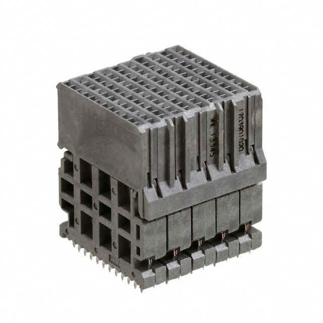
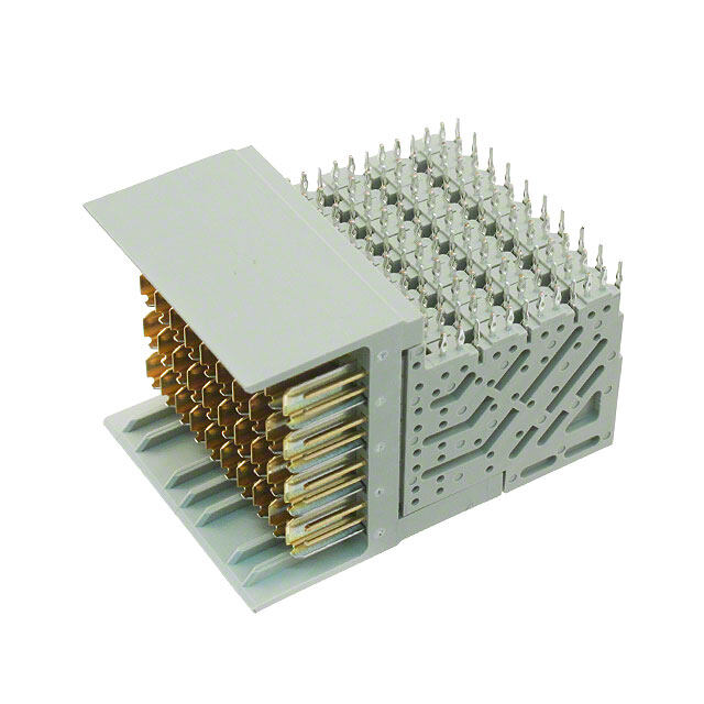
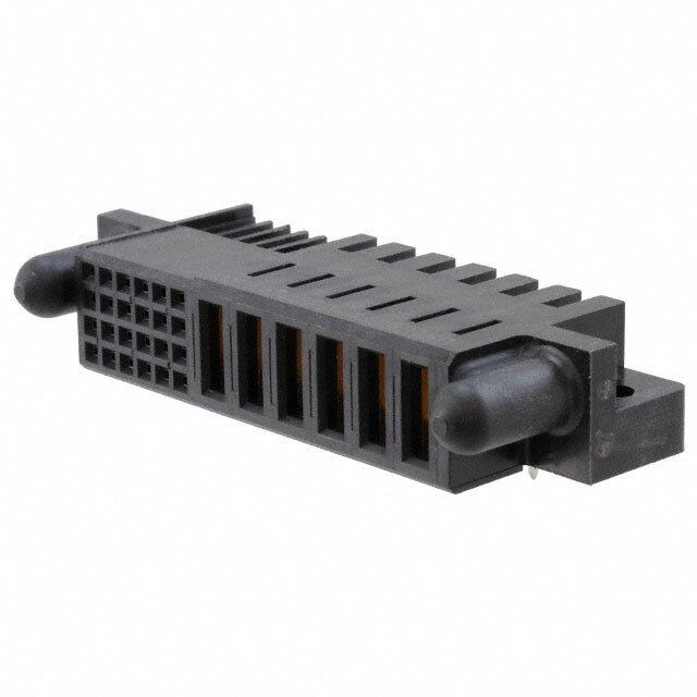
Cannon ZIF Connectors DLP - Metal Shell Cannon has developed a ‘Resilient Contact’ that provides reliable performance with contact wiping action directly on a PCB pad. A high density con- tact module enables a high pin count connector and flexibility. The nickel plated aluminum housing along with the embedded grounding springs offer supe- rior performance under the harshest EMI conditions. The DLP, like that of the DL, is capable of over 10,000 mating cycles. WIth the PCB acting as the mated contacts, electronics can be mounted at the signal source, thus reducing cross talk and minimizing real-estate. The DLP-408 is offered with mechanical shutters to meet the IEC requirements for finger protection. Materials and Finishes Housing Aluminum Alloy (DLP136, 204, 272). Zinc Alloy (DLP408) Nickel Plated Actuating Camshaft Stainless Steel, Passivated Electrical Data No. of Contacts: 136, 204, 272, 408 Wire Size: N/A Contact Termination: Receptacle DIP Soldering to PCB - DLP 136, 204, 272 Pressfit to PCB (408) Plug Cable termination to PCB Direct soldering to daughter board stacked to PCB Interface connector between cable and PCB Mechanical Data Actuation: Single Hand Coupling: Rotating Latch Polarization: Polarizing Posts Contact Spacing: 1.9 (0.075 Pitch (DLP136 204, 272), 1.6 (0.063) Pitch (DLP408) Shell Styles: Plug and Receptacle Performance Data Dielectric Withstanding Voltage: 500 VAC RMS Insulation Resistance 1000 Megaohms minimum Durability: 10,000 Cycles minimum Contact Resistance: 30 milliohms maximum (Initial) Contact Retention: 4.9N (1.1 LBS) Dimensions shown in mm (inch) Specifications and dimensions subject to change www.ittcannon.com 29
Cannon ZIF Connectors DLP - Metal Shell How to Order DLP R 272 - 8 - * SERIES DLP: Metal shell TYPE P - Plug R - Receptacle CONTACT ARRANGEMENT - NUMBER OF CONTACT MODULES - LOCATION DUMMY - MOD. CODE 136 - 4 AB 204 - 6 A 272 - 8 NONE DLP - 408 P - * SERIES DLP: Metal shell CONTACT ARRANGEMENT 408 TYPE AND MODIFICATION CODE - P (Plug) - R (Receptacle) Dimensions shown in mm (inch) Specifications and dimensions subject to change www.ittcannon.com 30
Cannon ZIF Connectors DLP - Metal Shell Plug • Order Protective cover, sold separately. See page 45. • For PC pad layout, see page 64. • Not including backshell, handle, and screw. • For contact cavity arrangements, see page 71. Part Number Nomenclature 127050-0299 DLP-P Part Number Description 127000-2721 DLP PWB Plate 8 127000-2721 DLP PWB Plate 6 M2.5 x 15mm PWB Plate Mounting Screw Note: Flat head screw length dependent on customer backshell design Receptacle • For PC hole pattern, see page 64. • For contact cavity arrangements, see page 71 Part Number Nomenclature 127050-0444 DLP-R204-6-A-F 127050-0391 DLP-R272-8-F Dimensions shown in mm (inch) Specifications and dimensions subject to change www.ittcannon.com 31
Cannon ZIF Connectors DLP - Metal Shell Plug • Order Actuating Handle Kit, sold separately. See page 44. • For Contact Cavity arrangements, see page 71. • For PC pad layout, see page 65. • PWB Protective Plate included. Screws sold separately. Part Number Nomenclature 127050-0516 DLP408P 127059-0053 PWB Plate Screws (center)* 127059-0054 PWB Plate Screws (corners)** * Two Center plate screws required. ** Four Corner plate screws required. Receptacle • For PC hole pattern, see page 65. • For contact cavity arrangements, see page 71. Part Number Nomenclature 127050-0452 DLP408R Dimensions shown in mm (inch) Specifications and dimensions subject to change www.ittcannon.com 32
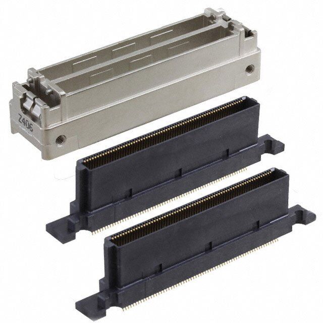
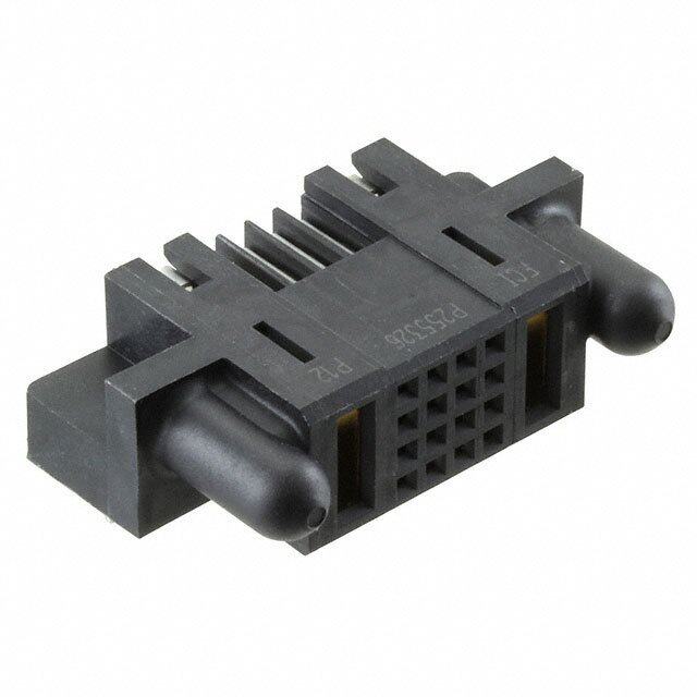
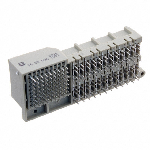
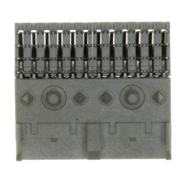
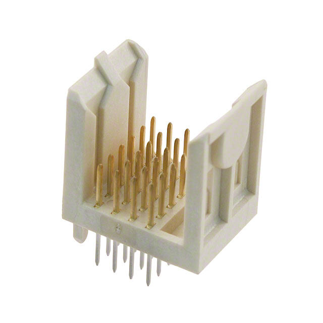
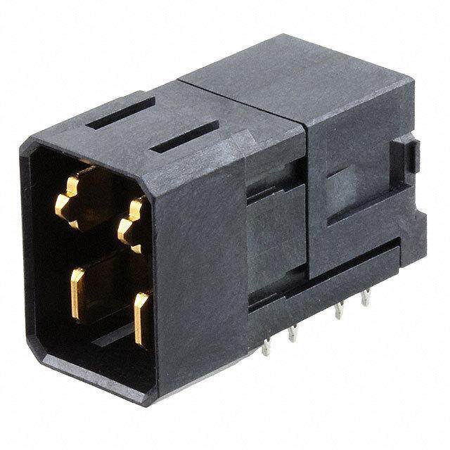
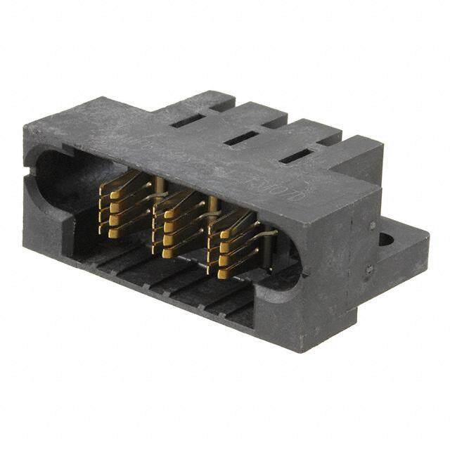
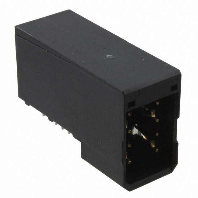
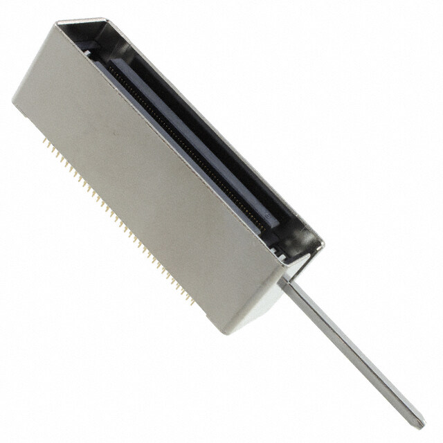
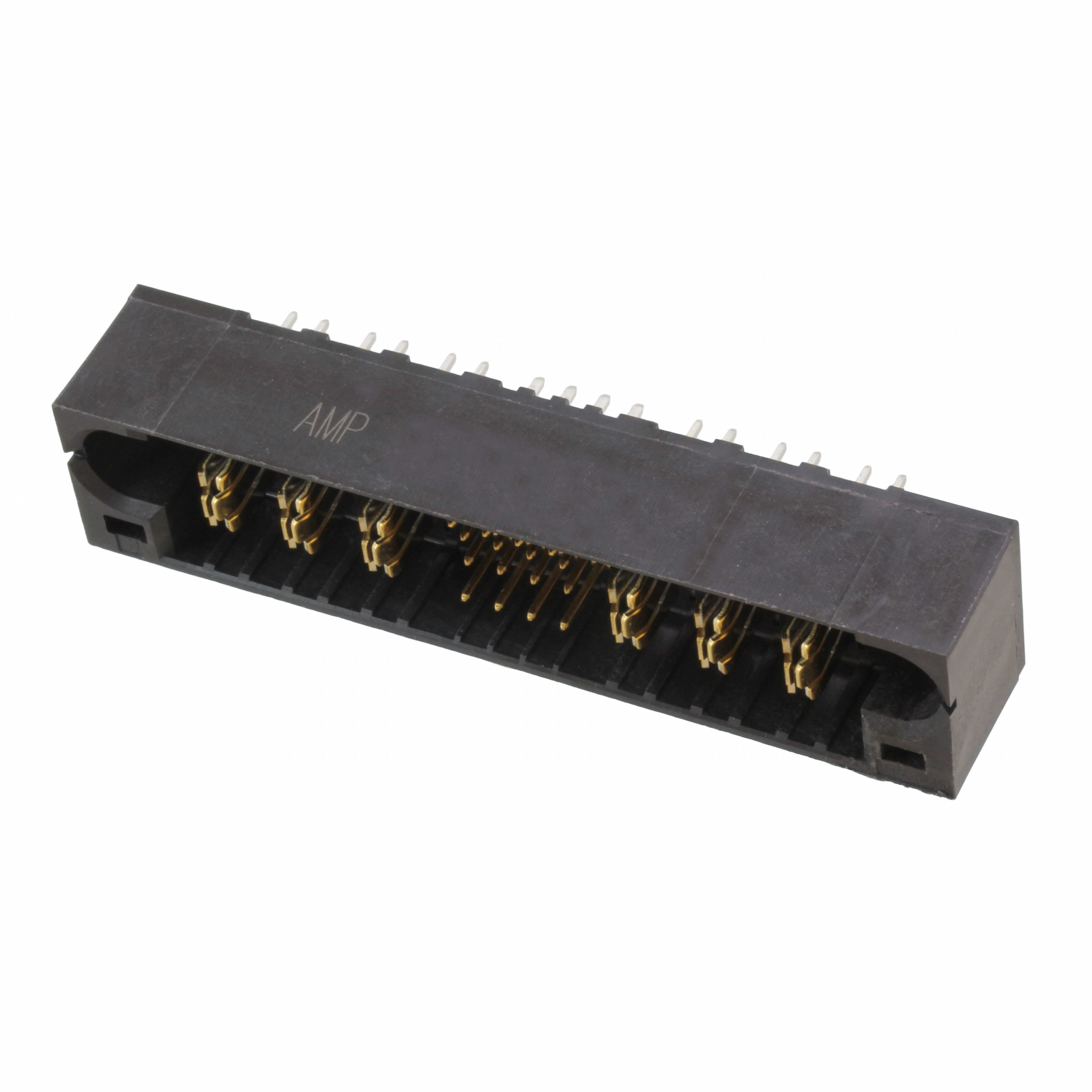
Cannon ZIF Connectors QLC ITT Expands its DL Family of Connectors with the Miniature QLC Device to Meet Size, Reliability, and Mating Requirements for Portable Medical Equipment Similar to the DL Series connectors, the QLC connector is highly reliable, easily assembled during harness and mating, and features a high pin count—up to 260 contacts in PC board-mount style. The QLC connector employs rugged nickel-plated aluminum housings and features a minimum rated life of 20,000 complete mating cycles with no performance loss. The inter- face of the QLC connector utilizes EMI springs and a shield-locking mechanism to ensure uniform mating pressure around the perimeter of the mated connec- tor, creating an EMI/RFI shield. With technology advances for small portable imaging equipment, the demand for a smaller, higher pin count, shielded, reliable connector proves essential. Consequently, ITT reduced the spacing from the standard DL to 0.8mm, thus reducing the overall size by more than 60% with the same number of contacts. The high pin count allows the engineer to utilize various grounding schemes to maintain signal integrity. The reduction in size, coupled with the superior shield design of the QLC, creates a sound interconnect choice for today’s portable market. Materials and Finishes QLC Housing: Zinc, Nickel plated Contacts: Copper Alloy, 40 μinches gold over nickel in mating area, gold flash over nickel in tail area Shaft Assembly: Stainless steel and plastic Ground Spring: Stainless steel Insert Mold: Plastic Electrical Data No. of Contacts: 260 Wire Size: N/A Contact Termination: Receptacle - DIP Solder to PCB Plug - Solder to Daughter Board Mechanical Data Actuation: Roating Handle Coupling: Quad Latch Polarization: Polarizing Posts Contact Spacing: 0.8mm Shell Styles: Plug and Receptacle Performance Data Dielectric Withstanding Voltage: 1000 VAC RMS Insulation Resistance 1000 Megaohms minimum Durability: 20,000 Cycles maximum Contact Resistance: 100 milliohms maximum (including bulk resistance) Contact Retention: N/A Dimensions shown in mm (inch) Specifications and dimensions subject to change www.ittcannon.com 33
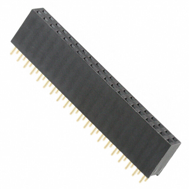
Cannon ZIF Connectors QLC Plug • Insulator retaining screw sold separately. • For PC hole pattern, see page 65. Part Number Nomenclature 127050-0529 QLC260P 127059-0067 Insulator Retaining Screw (2 required) Receptacle • Order actuating handle kit, sold separately. See page 44. • For contact cavity arrangements, see page 71. • For PC pad layout, see page 65. Part Number Nomenclature 127050-0530 QLC260R Dimensions shown in mm (inch) Specifications and dimensions subject to change www.ittcannon.com 34
Cannon ZIF Connectors Accessories - Overview Cannon offers a wide selection of accessories that allow the design engineers to config- ure the product for their exact needs. The accessories range from the simple actuating handle to junction and backshells, as well as polarizing posts and protective covers for the contacts. Actuating handles are the same for the DL1/2/3 and DLM1/2/3 series. The DL5/DLM5 and DLM6 series have specific handles. Handles are sold separately since many applications require the connector to be attached or removed only by an authorized technician. Plastic junction shells are available for the DL1/2/3 series for encasement of the crimp contacts after complete installation into the connector. These shells also make it possi- ble for the DL to be used as a cable-to-cable mating connector as they can be used both on the plug and the receptacle. The DL1/2/3 plastic junction shells have optional secondary cable entry capability by removing the mold- ing in the cable entry plugs. Cable clamp kits are available to affix the cable to the second entry. This second entry option is very useful Polarizing posts ar available to offer offer contact protection from physical in applications where the large wire sizes a keying feature for both the DL and damage or dust. Since the DL series make the cable diameter too large to be DLM connectors. The polarizing posts has a high density of contacts in an handled from a single entry port. can be installed in specific orienta- exposed area, these covers are very use- tion so that plugs of the same size ful for many applications. For example, Metal Backshells are available for the entire connectors can only be mated in pre- where systems have multiple connec- DL/DLM series. The metal backshells are determined receptacles. This feature tors, or when the connections are often constructed from die cast aluminum with a offers the designer the ability to fool- left unattached, or when the system nickel plating to facilitate in EMI/RFI shield- proof the attachment possibilities parts are put into storage. ing of the connector systems. Shielding has to protect accidental damage to the become a driving force because of the ever system. Protective covers of plastic increasing stringent EMI/RFI regulations and anti-static rubber are available to Accessory Selection Guide Protective Metal Shell Plastic Actuating Covers EMI/RFI Junction Cable Metal Polarizing Connector Handles Rubber Plastic Shielding Shell Clamps Backshell Posts Series see page see page see page see page see page see page see page see page DL1-156 – DL2-96 – DL3-60 – DL4-624 included – – – – – – DL5-260 – – – – DLM1-156 – DLM2-96 – DLM3-60 – DLM5-260 – – – –– DLM6-360 – – – – Compatible –Not Compatible Dimensions shown in mm (inch) Specifications and dimensions subject to change www.ittcannon.com 35
Cannon ZIF Connectors Accessories - Plastic Junction Shells Product Features • Stainless steel cable clamps • For use with crimp contact connectors • Thermoplastic UL 94V-1 rated • Knockout plug provides alternate second entry • Straight 90 or 45 cable entry • Complete with 4 attaching screws and nuts • Accommodates up to 22,22 (.875) cable • Complete with one cable clamp kit Junction Shell Kit (Straight or 90º Mounting) DL1 / DLM1 Part Max Description A B C D E F G H I Number Cable Entry 110, 74 62,3 6 68 ,58 86 ,36 4 3,94 5 7,78 63,50 27,69 50,44 22,2 3 DL-1-J/ S 249-1950 -000 (4.360) (2.455) (2.700) (3.400) (1.730) (2.275) (2.500) (1.090) (1.988) MA X MA X M AX M AX M AX M AX MAX MAX MAX (0.875) Note: Single Piece Shell DL2 / DLM2 DL3 / DLM3 Part Max Description A B C D E F G H I Number Cable Entry 68,83 46,81 52,45 71,04 30,05 36,45 39,29 31,75 44,04 D L2-J/ S 249-198 5-000 (2.7 10) (1. 843) (2.065) (2.797) (1.183) (1.435) (2.500) (1.547) (1.250) 14,20 MA X M AX MAX MAX MAX MAX MAX MAX MAX (0.560) 68,83 46,81 52,45 71,04 30,05 36,45 39,29 31,75 44,04 DL2-2 -J/S 249-22 38-000 (2.7 10) (1.8 43) (2.065) (2.797) (1.183) (1.435) (2.500) (1.547) (1.250) 15,9 0 MA X M AX MAX MAX MAX MAX MAX MAX MAX (0.625) 68,83 46,81 52,45 71,04 30,05 36,45 39,29 31,75 44,04 22,23 DL2-4- J/S 249-22 38-001 (2.710) (1.843) (2.065) (2.797) (1.183) (1.435) (2.500) (1.547) (1.250) MA X M AX MAX MAX MAX MAX MAX MAX MAX (0.875) 68,83 46,81 52,45 71,04 30,05 36,45 39,29 31,75 44,04 14,20 D L3-J/S 249-206 0-000 (2.710) (1.843) (2.065) (2.797) (1.183) (1.435) (2.500) (1.547) (1.250) MA X M AX MAX MAX MAX MAX MAX MAX MAX (0560) 68,83 46,81 52,45 71,04 30,05 36,45 39,29 31,75 44,04 DL3-3- J/S 249-22 37-000 (2.7 10) (1.8 43) (2.065) (2.797) (1.183) (1.435) (2.500) (1.547) (1.250) 15,9 0 MA X M AX MAX MAX MAX MAX MAX MAX MAX (0.625) 68,83 46,81 52,45 71,04 30,05 36,45 39,29 31,75 44,04 DL3-4- J/S 249-22 37-001 (2.7 10) (1.8 43) (2.065) (2.797) (1.183) (1.435) (2.500) (1.547) (1.250) 22,2 3 MA X M AX MAX MAX MAX MAX MAX MAX MAX (0.875) Note: Two Piece Shell Junction Shell Kit (45º Mounting) DL2 / DLM2 DL3 / DLM3 Description Part A B C D E F G H I Max Number Cable Entry 68,83 46,81 52,45 71,04 30,05 36,45 39,29 31,75 44,04 15, 90 DL2-1-J/S 249-1985-001 (2.710) (1.843) (2.065) (2.797) (1.183) (1.435) (2.500) (1.547) (1.250) (0.625) MAX MAX MAX MAX MAX MAX MAX MAX MAX 68,83 46,81 52,45 71,04 30,05 36,45 39,29 31,75 44,04 15, 90 DL3-2-J/S 249-2060-001 (2.710) (1.843) (2.065) (2.797) (1.183) (1.435) (2.500) (1.547) (1.250) (0.625) MAX MAX MAX MAX MAX MAX MAX MAX MAX Note: Two Piece Shell Dimensions shown in mm (inch) Specifications and dimensions subject to change www.ittcannon.com 36
Cannon ZIF Connectors Accessories - Cable Clamp Kits Cable Clamp Kit for optional second entry (Straight or 90º Mounting) DL1 / DL2 / DL3 Part Max Description Mounting Number Cable Entry 22,23 Straight or 90° DL1-C/C 218-0179-000 (0.875) 14, 20 Straight or 90° DL2-C/C 218-0180-000 (0.680) 15, 90 DL2-2-C/C (1) 218-0181-001 (0.625) Straight or 90° 22, 23 DL2-3-C/C (1) 218-0200-000 (0.875) Straight or 90° Cable Clamp Kit for optional second entry (45º Mounting) DL2 Part Max Description Mounting Number Cable Entry 15, 90 DL2-1-C/C (1) 218-0181-000 45° (0.625) Note: (1) Also suitable for DL3 Connectors Dimensions shown in mm (inch) Specifications and dimensions subject to change www.ittcannon.com 37
Cannon ZIF Connectors Accessories - Metal Backshells Standard Materials and Finishes Shell: Acrylic paint over die cast aluminum Hardware: Stainless Steel Two Piece Shell Design (Straight or 90º Mounting) DL2 / DLM2 A DL3 / DLM3 D 1 E B CL C F Wire hood may be installed in two positions. 90° cable entry as shown or straight entry by rotating wire hood. Used Part Max A B C D E F On Number Cable Entry D L2 / D LM2 (1) 249-45 1 7-000 (737.0 ,68) (13.33 ,00) (26.55 ,98) (13.64 ,33) (2.94 6,5) (218.1 .11) (109.7,0550 ) D L3 / D LM3 (1) 249-451 8-000 (737.0 ,68) (13.33 ,00) (26.55 ,98) (13.64 ,33) (2.49 ,65) (218.1 .11) (109.7,0550 ) Note: Kit consists of 2 shells, 9 screws, 1 wire hood, 1 wire clamp, 1 lock/open indication seal. One Piece Shell Design (Straight or 90º Mounting) DL1/DLM1 DL5/DLM5 1 G DLM6 E B D CL CL C F Wire hood may be installed in two positions. 90° cable entry as shown or straight entry by rotating wire hood. Used Part Max A B C D E F On Number Cable Entry DL1/ DLM1 (2) 249-4520-000 (142,38,64) (418.9,61 ) 1(41.138,4) N/ A (02.494,05 ) 2(18.,1112) (109.7,5005) 49,0 115,8 7,6 30,0 42,6 22,3 DL5/ DLM5 (3) 249-4501-000 N/A (1.93) (4.56) (0,30) (1.18) (1.68) (0.875) 63,0 125,0 7,6 30,0 42,6 28,00 DL6/ DLM6 (3) 249-4515-000 N/A (2.48) (4.92) (0,30) (1.18) (1.68) (1.102) Notes: (2) Kit consists of 2 shells, 10 screws, 1 wire hood, 1 wire clamp, 1 lock/open indication seal. (3) Kit consists of 1 shell, 8 screws, 1 wire hood, 1 wire clamp, 4 nuts. Dimensions shown in mm (inch) Specifications and dimensions subject to change www.ittcannon.com 38
Cannon ZIF Connectors Accessories - Actuating Handle Kits Product Features • Provides a convenient method of actuating the contacts and cam for locking the connector. • Kit provides actuating handle and attaching screw. • Pointer on handle denotes “locked” and “open” positions. Materials and Finishes Handle: Glass filled thermoplastic DL1 / DL2 / DL3 DLM1 / DLM2 / DLM3 Part Number: 204-0016-000 DL5 DLM5 DLP408 Part Number: 204-4501-000 DLM6 Part Number: 204-4500-000 QLC Part Number: 127059-0069 Note: For DLP 272 Handle, please consult factory for more information. Dimensions shown in mm (inch) Specifications and dimensions subject to change www.ittcannon.com 39
Cannon ZIF Connectors Accessories - Protective Covers Protective Covers Product Features • Fits snugly over mating faces • Prevents foreign matter from permeating contact cavities Protective Covers - Rubber Materials and Finishes Cover: Anti-static synthetic rubber DL / DLM Receptacle Cover for Part Number DL1-156R 039-0243-000 DL2-96R 039-0245-000 DL3-60R 039-0247-000 DL4-624R 039-0240-000 DL / DLM Plug Cover for Part Number DL1-156P 039-0242-000 DL2-96P 039-0244-000 DL3-60P 039-0246-000 DL4-624P 039-0239-000 Protective Covers - Plastic Materials and Finishes Cover: Polyethylene DL / DLM Plug Cover for Part Number DL1-156P 025-0852-000 DL2-96P 025-0857-000 DL3-60P 025-0850-000 DL / DLM Receptacle Cover for Part Number DL1-156R 025-4506-000 DL2-96R 025-4505-000 DL3-60R 025-4509-000 DL5-260R 025-1218-000 Note: Must remove/cut secondary cap from DL5 cover DLP 272 Nomenclature Part Number DLP PWB Protect 6A/H 127000-2721 DLP PWB Protect 8 127000-2720 DLP Plug Dust Cap 127000-2719 DLP Receptacle Dust Cap 127000-2732 Dimensions shown in mm (inch) Specifications and dimensions subject to change www.ittcannon.com 40
Cannon ZIF Connectors Accessories - Polarizing Posts Center Mounting Materials and Finishes Post: Zinc, copper over nickel Screw: Stainless Steel DL1 / DL2 DLM1 / DLM2 Kit consists of Part Number 2 posts and 2 no, 2- 56 X3/ 320-0021-005 fil. Head screws Corner Mounting Materials and Finishes Post: Zinc, nickel Screw: Stainless Steel DLM1 / DLM2 / DLM3 Kit consists of Part Number 2 posts and 2 No. 4-40x9/32 320-0021-006 DL1 / DL2 / DL3 / DLM1 / DLM2 / DLM3 with Metal Back shell Kit consists of Part Number 4 posts and 4 M2.5x10 screws 320-4505-000 DL5 DLM5 Kit consists of Part Number 4 posts and 4 M3x8 screws 320-4502-000 Dimensions shown in mm (inch) Specifications and dimensions subject to change www.ittcannon.com 41
Cannon ZIF Connectors Accessories - EMI / RFI Shielding Shells Materials and Finishes Shell: Steel, Nickel Finish Metal Shells (DL5 only) Plug Description Part Number Plug Shell 248-4500-000 Receptacle Description Part Number Receptacle Shell 248-4501-000 Dimensions shown in mm (inch) Specifications and dimensions subject to change www.ittcannon.com 42
Cannon ZIF Connectors Contacts The Cannon DL Crimp and Buss contacts are available in addition to the factory installed Square Post/PCB mount version contacts. Crimp contacts are available loose only. The Buss Contacts make the DL series capa- ble of providing higher than 5 amps per line. The Buss contacts are pairs of contact lines which increase the amperage capability in increments of 10 amps up to 60 amps. The contacts have solder holes at the tail section for soldering #30-#18 AWG. The tail is also designed to accommodate a 1/8 crimp lug for wire sizes larger than #18. The Crimp contacts are available in two plat- ing types. The 20μ inch gold hermaphroditic version which is the economical choice for applications requiring over 100 milliamps to 5 amps, and the 50μ gold bump to flat ver- sion which offers the most versatile range of applications requirements from micro-amps to 5 amps. The Bump to Flat version was developed specifically to handle “dry circuit” requirements where the signal amperage is not enough to ensure a clean contact point. The 50μ inch gold Bump to Flat version is man- datory for applications with signals below 100 milliamps. The Bump contact is installed in the Plug and the Flat contact is installed in the receptacle. This combination increases the contact force and ensures that the wiping point becomes the current carrying point after mating. The 50μ inch gold Bump to Flat version has become the standard for all modern applications where power and low voltage signals are combined into one connector. Dimensions shown in mm (inch) Specifications and dimensions subject to change www.ittcannon.com 43
Cannon ZIF Connectors Contacts - Buss Contacts 1 Pair • Designed for power distribution of more than 5 amps. • Accommodates #30-#18 AWG in hole 1,29-1,14 Buss Contact (.051-.045) for wire soldering. • Accommodates 1/8 crimp lugs for larger wire sizes. Description Part Number 1 Pair 030-7380-001 2 Pair 030-7380-002 3 Pair 030-7380-003 4 Pair 030-7380-004 5 Pair 030-7380-005 Material: Copper Alloy 6 Pair 030-7380-006 Finish: 20μ inch in mating area / gold flash on balance (terminating end) Note: For more information on tools and assembly, see pages Wire Termination - Solder Wire Termination - Crimp Lug Wire Termination — Solder Wire Termination — Crimp Lug Note: Contacts must be installed in the vertical position. Dimensions shown in mm (inch) Specifications and dimensions subject to change www.ittcannon.com 44
Cannon ZIF Connectors Contacts - Crimp Contacts 50 inch Gold Contacts • Recommended for all applications • Offer the broadest amperage range • Mandatory for low current applications, less than 100 milliamps. Materials and Finishes Material: Copper Alloy Finish: 50 inch Gold over Nickel in mated area, Gold flash on balance (terminating end) Plug (Bump) Wire Loose Reeled Type Part Number Part Number 28 thru 32 AWG 030-2416-003 110238-0482 24 thru 26 AWG 030-2410-003 110238-0480 20 thru 22 AWG 030-2409-003 110238-0479 18 thru 20 AWG (1) 030-2415-003 110238-0481 Note: Contact can be used in both plug and receptacle for appli- BUMP RETENTION CONTACT LANCE cations above 100 MA. Receptacle (Flat) Wire Loose Reeled Type Part Number Part Number 28 thru 32 AWG 030-2494-001 110238-0486 24 thru 26 AWG 030-2492-001 110238-0484 FLAT RETENTION CONTACT LANCE 20 thru 22 AWG 030-2491-001 110238-0483 18 thru 20 AWG (1) 030-2493-001 110238-0485 Caution: Flat contacts can only be used in the receptacle 20 inch Gold Contacts Materials and Finishes Material: Copper Alloy Finish: 20 inch Gold over Nickel, in mated area, Gold flash on balance (terminating end) Plug and Receptacle (Bump) (3) Wire Loose Reeled Type Part Number Part Number 28 thru 32 AWG 030-2416-001 110238-0403 24 thru 26 AWG 030-2410-001 110238-0401 20 thru 22 AWG 030-2409-001 110238-0400 18 thru 20 AWG 030-2415-001 110238-0402 Note: (1) Non insulation support (2) 20 inch gold in mating area/Gold flash on balance (terminating end), RoHS compliant, sold in lots of 100 pieces. (3) 20 inch gold Bump contact are used for both Plug and Receptacle Dimensions shown in mm (inch) Specifications and dimensions subject to change www.ittcannon.com 45
Cannon ZIF Connectors Tools and Assembly A key feature of the Cannon DL connector series is easy contact termination, both in the field and in high-volume production. An ergonomically designed hand crimp tool is available for the low volume (loose contact) applications and will accommodate two different crimp contact sizes. To reduce overall costs, the crimp jaws are replaceable. Automatic crimp and strip/crimp machines are avail- able for high volume applications requiring a large number of crimps (50,000 crimps per year or more). These machines are leased to customers to eliminate the need for heavy investment. They also improve productivity for large pin count applications. DL Crimp contacts are designed to be hand installed into the connector, no tooling is needed for the insertion process. Extraction tools are available for the removal of Crimp contacts for easy repair even in field applications. Extraction tools are also available for the Buss contacts, as well as the factory installed Square Post contacts. Hand Crimp Tool Hand Crimp Tool Hand Tool Description Part Number 1 CHDLT 28-32 112108-0002 2 CHDLT 20-26 112108-0001 3 CHDLT 18-20 112108-0000 Crimp Tensile Strength Crimp tensile strength is a measure of Wire Trim Dimension how hard a wire can be pulled without breaking or separating from the contact. This is the best way to verify that the wire is properly terminated to the contact. Periodic crimp tensile measurements are recommended to insure the integrity of the crimp. The table below contains the appropriate values for DL crimp contacts. Wire Size (AWG) 32 30 28 26 24 22 20 18 Tensile Min. (lbs) 1 1.5 3 7 10 15 19 30 Wire Trim Dimension “A” 3,30 (.130) 3,30 (.130) 3,30 (.130) 3,30 (.130) 3,30 (.130) 3,30 (.130) 4,06 (.160) 4,06 (.160) Insulation Dia. Max 1,35 (.053) 1,35 (.053) 1,35 (.053) 1,65 (.065) 1,65 (.065) 1,88 (.074) 1,88 (.074) 1,88 (.074) Dimensions shown in mm (inch) Specifications and dimensions subject to change www.ittcannon.com 46
Cannon ZIF Connectors Contacts - Crimp Contacts - Reeled Extraction Tool - Buss Contacts Extraction Tool for Buss Contact Description Contacts Part Number CET-DL3 1 pair 274-7029-003 CET-DL4 2 pair 274-7029-004 CET-DL4 3 pair 274-7029-004 CET-DL5 4 pair 274-7029-005 CET-DL6 5 pair 274-7029-006 CET-DL6 6 pair 274-7029-006 Extraction Tool - Crimp, Square Post, PC/RC Contacts CET-DL10 CET-ECP CET-ECP-1 Description Part Number Contact Type PC Tail Extension CET-DL10 274-7029-007 Crimp - CET-ECP 274-7045-000 Wrap Post 15,37 (.605) CET-ECP-1 274-7045-001 Square Post 7,11 (.280) Dimensions shown in mm (inch) Specifications and dimensions subject to change www.ittcannon.com 47
Cannon ZIF Connectors Tools and Assembly - Crimp Contacts Assembly Instructions for Crimp Contacts RECEPTACLE CONNECTOR Contact Insertion: All crimp contacts inserted by hand. No tooling is required for either the plug or RETENTION PLUG LANCE receptacle. CONNECTOR (BOTTOM) Caution: Do not force contacts into contact cavities. If contact encounters RETENTION excessive resistance during installation LANCE remove and re-insert using a slight up (TOP) and down motion. This will assure positive RETENTION cavity alignment. Do not install contact if LANCE (TOP) plug is in the closed or actuated position. Plug: Step 1. Prior to inserting contacts, turn the SCREW shaft counter-clockwise to its maximum open position. CAM Step 2. WIth the retention lance positioned away from the shaft, insert contacts from the rear of the contact plug. Receptacle: Step 1. With the retention lance positioned POLARIZING RETENTION POST toward the shaft hole, insert contacts from LANCE the rear of the receptacle. (BOTTOM) Contact Removal for Crimp Contacts Tool: CET-DL10 CONTACT RETENTION LANCE Release retention lance by inserting tip of extraction tool into cavity until it bottoms on insulator shoulder. Gently pull wire in direction of arrow, see illustration, to remove contact from insulator. Dimensions shown in mm (inch) Specifications and dimensions subject to change www.ittcannon.com 48
Cannon ZIF Connectors Tools and Assembly - Buss Contacts Assembly Instructions for Buss Contacts Contact Insertion: All buss contacts are inserted by hand. No RECEPTACLE tooling is required for either the plug or CONNECTOR receptacle. RETENTION Caution: Do not force contacts into PLUG LANCE contact cavities. If contact encounters CONNECTOR (BOTTOM) excessive resistance during installation remove and re-insert using a slight up RETENTION and down motion. This will assure positive LANCE (TOP) cavity alignment. Do not install contact if RETENTION LANCE plug is in the closed or actuated position. (TOP) Plug: Step 1. Prior to inserting contacts, turn the shaft counter-clockwise to its maximum SCREW open position. Step 2. WIth the retention lance positioned CAM away from the shaft, insert contacts from the rear of the contact plug. Receptacle: Step 1. With the retention lance positioned POLARIZING POST toward the shaft hole, insert contacts from the rear of the receptacle. RETENTION LANCE (BOTTOM) Contact Removal for Buss Contacts Tool: CET-DL3/4/5/6 CONTACT RETENTION LANCE CONTACT RETENTION LANCE Release retention lance by inserting tip of extraction tool into cavity until it bottoms on insulator shoulder. Gently remove buss con- tact in direction of arrow, see illustration, to remove contact from insulator. Dimensions shown in mm (inch) Specifications and dimensions subject to change www.ittcannon.com 49
Cannon ZIF Connectors Tools and Assembly - Square / Wrap Post Contacts Assembly Instructions for Square Post Contacts Contact Insertion: Square Post Contacts are factory installed but can be removed and replaced if damaged in service. Step 1. Prior to inserting contacts, actuating handle must be in the maximum open position. Step 2. Contacts are inserted from the insulator front face by hand and are seated and clicked in the cavity by pulling on the terminal post with flat nose plier, see Figure 1. CONTACT Figure 1 RETENTION LANCE CONNECTOR FRONT FACE Contact Removal for Square Post Contacts Tool: CET-ECP and CET-ECP-1 Place tool over square post terminal and impact tool. Apply sufficient force to collapse retention lance and push contact out of insulator. This process destroys the retention lance CONTACT RETENTION LANCE Dimensions shown in mm (inch) Specifications and dimensions subject to change www.ittcannon.com 50
Cannon ZIF Connectors Tools and Assembly Lease Automatic Tooling - North America* Mini Applicators are interchangeable mod- ules that will fit into many standard crimping machines. They are available for all sizes of stamped and reeled contacts Wire Size AWG 18-20 20-22 24-36 28-32 20 μinches Gold 110238-0402* 110238-0400 110238-0401 110238-0403 50 μinches Gold (Bump) 110238-0481* 110238-0479 110238-0480 110238-0482 50 μinches Gold (Flat) 110238-0485* 110238-0483 110238-0484 110238-0486 * Without Insulation support Mini Applicator DL-T 18-20 DL-T 20-22 DL-T 24-26 DL-T 28-32 Applicator p/n 112211-0002 112211-0003 112211-0009 112211-0010 Wire Size 18 20 20 22 24 26 28 30 32 4.00 4.00 3.3 3.3 3.3 3.3 3.3 3.3 3.3 Strip Length Reference (0.160) (0.160) (0.130) (0.130) (0.130) (0.130) (0.130) (0.130) (0.130) Conductor Crimp Width - 1,80 1,80 1,710 1,710 1,5 1,5 1,5 1,5 1,5 Max (0.071) (0.071) (0.067) (0.067) (0.059) (0.059) (0.059) (0.059) (0.059) Conductor Crimp Height 1,52 1,34 1,25 1,22 1,04 0,96 0,84 0,79 0,74 +/- 0,03 (0.001) (0.060) (0.053) (0.049) (0.048) (0.041) (0.038) (0.033) (0.031) (0.029) Insulation crimp Heigh - 1,88 1,88 1,65 1,65 1,35 1,35 1,35 N/A N/A Max (0.074) (0.074) (0.065) (0.065) (0.053) (0.053) (0.053) Tensile Pull Minimum 133 (30) 84 (19) 84 (19) 67 (15) 44 (10) 31 (7) 13 (3) 7 (1.5) 4 (1) (Newtons) ABT-620 UCCS The ABT-620 Universal Cannon Crimper / Machined Strip / Crimp Rate: Stripper is a pneumatic powered, micropro- 1200+ per hour cessor controlled machine. It is designed to semi-automatically strip insulation from strand- Power Requirements: ed or single conductor electrical wire and attach Electrical = 115 VAC, 60 Hz, 20A a stamped and formed contact by crimping. Pneumatic = 80 psi, 3 cu. ft per min. The machine will accommodate 34 thru 12 AWG wire. Primary application of the machine is the termination of jacketed cable where the individual leads cannot be stripped by fully automated equipment. The ABT-620 UCCS operates automatically upon insertion of a wire or it can be switched over to a foot pedal operation as desired. * For other geographical regions, contact Cannon for details. Dimensions shown in mm (inch) Specifications and dimensions subject to change www.ittcannon.com 51
Cannon ZIF Connectors Tooling - Automatic Tooling Lease or Buy Automatic Tooling - Europe TT Crimping Press The TT Crimping Press is available either in semi-au- Part Number: 121586-5225 tomatic (for bench-top use) configuration or in full automatic (integrated into a cut and strip machine) configuration. Very compact and light, its spheroidal cast iron, one-piece structure offers the highest rigidity for a very stable crimping height value. A proprietary safety cover (grants the operator a perfect view of the crimping zone while enjoying complete protection from any hazard. The semi-automatic configuration (for bench top use) always includes safety cover, reel arm, foot switch according to the international safety standard and CE regulation. Mini-applicators are available for all sizes of stamped and reeled contacts. Mini-Applicators - Europe Wire Size AWG 18-20 20-22 24-26 28-32 20 μinches Gold 110238-0400 110238-0401 110238-0403 50 μinches Gold (Bump) - 110238-0479 110238-0480 110238-0482 50 μinches Gold (Flat) - 110238-0483 110238-0484 110238-0486 Mini Applicator DL-T 18-20 DL-T 20-22 DL-T 24-26 DL-T 28-32 Applicator p/n - - - - Wire Size AWG 18 20 20 22 24 26 28 30 32 mm2 0,82 0,52 0,52 0,33 0,25 0,14 0,08 0,05 0,03 4.00 4.00 3.30 3.30 3.30 3.30 3.30 Strip Length Reference - - (0.160) (0.160) (0.130) (0.130) (0.130) (0.130) (0.130) Conductor Crimp Width - 1,80 1,80 1,70 1,700 1,50 1,50 1,5 - - Max (0.071) (0.071) (0.067) (0.067) (0.059) (0.059) (0.059) Conductor Crimp Height 1,45 1,35 1,22 1,14 1,07 1,04 0.90 - - +/- 0,03 (0.001) (0.057) (0.053) (0.048) (0.045) (0.042) (0.041) (0.035) Insulation Crimp Height - 1,88 1,88 1,65 1,65 1,65 0 0 - - Max (0.074) (0.074) (0.065) (0.065) (0.065) Tensile Pull Minimum 133 84 84 53 32 18 11 - - (Newtons) Note: All applicators are compatible with TT Crimping Press, #121586-5225. We advise all our customers to hold at least one set of consumable tooling (consisting of Conductor Crimp Blade, Insulation Crimp Blade, Combination Anvil, Shear Moving and Shear Fixed). Please consult factory to order consumable tooling. Dimensions shown in mm (inch) Specifications and dimensions subject to change www.ittcannon.com 52
Cannon ZIF Connectors PCB Hole Pattern and Pad Layout PCB Pad Layout For the PC/RC Versions: The contact tail design has been modified from a 0,64 (.025) square pin to a 0,05 (.020) diameter round pin. The change enables a decrease in the diameter of the through holes as well as the solder mounds on PCB’s (d1 and d2 can be wider than D1 and D2). This can reduce the crosstalk in RF circuits and enhance the dielectric withstanding voltage in high voltage circuits. The soldering of contacts into through (THRU) holes on a PC Board has become standard for medical equipment and test equipment for semi-conductors. As a CONTACT CONNECTOR result of the narrow spacing between the solder pad and circuit pattern, cross- INSULATOR talk between signals increases. A solution to this problem is to make the diame- ter of the contacts and solder lands smaller to provide more space between the lands and the patterns. However a smaller diameter contact results in higher impedance. Cannon designed a solution with a smaller diameter contact tail. This design application allows the use of a smaller through-hole diameter. THRU HOLE PCB SOLDER PC TAIL Dimensions shown in mm (inch) Specifications and dimensions subject to change www.ittcannon.com 53
Cannon ZIF Connectors PCB Hole Pattern and Pad Layout DL1 / DLM1 / DLD1 Printed Circuit Board Hole Patterns DL1-156/DLM1-156 Plug Receptacle 16,26 (.640) 3,30-3,05 5 EQUAL SPACES @ 4X Ø (.130-.120) 2 , 5 4 ( . 1 0 0 ) CENTERS Ø 0,25 (.010) A B = 12,70 (.500) TOTAL THRU HOLE CL NON-ACCUMULATIVE CL SYMM SYMM A A B B C C 12 EQUAL SPACES @ D D EF EF 2 , 5 4 ( . 1 0 0 ) CENTERS G G HKLJ 3 156X Ø(.10,4039--.00,3974) HKLJ = N3O0N,4-8A C(1C.2U0M0)ULATTOIVTEAL M M N Ø 0,13 (.005) A B N 100,02 (3.938) CL PLATED THRU HOLE CL 16,51 (.650) SYMM SYMM B P P Ø 9,52 (.375) MIN R R THRU HOLE WcaTVbUXYZS WcaTVbUXYZS123456 = N1O3220N, 5E,-44QA8 (CU .(1CA10.LU20 MS0)0PU)ALCCAETETISNOV TTE@EARLS 65432 1 1 A DLD1-156 Plug Receptacle 20,32-19,81 20,32-19,81 (.800-.780) 5 EQUAL SPACES @ (.800-.780) 4X R 3,63 (.143) MAX 2,54 (.100) CENTERS = 12,70 (.500) TOTAL SYMM NON-ACCUMULATIVE SYMM 4X R 3,63 (.143) MAX A A B B C C DE 40,89-40,39 DE 12 EQUAL SPACES @ F (1.610-1.590) F 2,54 (1.00) CENTERS G G H H = 30,48 (1.200) TOTAL J J NON-ACCUMULATIVE K K L L M M N N 92,20-91,69 (3.630-3.610) 3,18-2,92 16,51 (.650) REF SYMM (.125-.115) SYMM P B P R R Ø 9,52 (.375) MIN ST 1,09-0,94 ST 12 EQUAL SPACES @ THRU HOLE UV 156X Ø(.043-.037) UV 2,54 (1.00) CENTERS W Ø 0,13 (.005) A B W = 30,48 (1.200) TOTAL X X Y PLATED THRU HOLE Y NON-ACCUMULATIVE Z Z a a b b c c 65432 1 123456 Notes: 1 A 1. Contact hold cavity identifications shown are typical as viewed from top surface of P.C. board. 2. All plug layout dimensions not shown are similar to the receptacle dimensions 3. Plated through (THRU) hole diameters shown are for 0,64 (.025) post contacts. PC/RC contact plated through (THRU) hole diameters are 0,79 - 0,64 (.031-.025). For PCB pad layout configuration see page Dimensions shown in mm (inch) Specifications and dimensions subject to change www.ittcannon.com 54
Cannon ZIF Connectors PCB Hole Pattern DL2 / DLM2 / DLD2 Printed Circuit Board Hole Patterns DL2-96/DLM2-96 Plug Receptacle 19,38 (.763) 6 EQUAL SPACES @ 7 EQUAL SPACES @ 2 . 5 4 ( . 1 0 0 ) CENTERS 2 , 5 4 ( . 1 0 0 ) CENTERS = 1 5 , 2 4 ( . 6 0 0 ) TOTAL = 1 7 , 7 8 ( . 7 0 0 ) TOTAL NON-ACCUMULATIVE CL NON-ACCUMULATIVE CL ABC SYMM 3 96ØX 0Ø,1 (31.0 ,(04.0930--0.50,)9347 A) B ABC SYMM 57,91 (2.280) DE PLATED THRU HOLE DE F F CL G CL G 6,35 (.250) SYMM H SYMMH J B J K K Ø 9,52 (.375) MIN L L M M THRU HOLE NP 876 54 32 1 NP 12345678 1 A 6 EQUAL SPACES @ 2 , 5 4 ( . 1 0 0 ) CENTERS 3,30-3,05 4X Ø (.130-.120) = 1 5 , 2 4 ( . 6 0 0 ) TOTAL Ø 0,25 (.010) A B NON-ACCUMULATIVE THRU HOLE DLD2-96 Plug Receptacle 7 EQUAL SPACES @ 22,86-22,35 2,54 (.100) CENTERS (.900-.880) = 17.78 (.700) TOTAL 24,13-23,62 NON-ACCUMULATIVE 10,16-9,65 (.950-.930) 1,09-0,94 (.400-.380) 4X R 3,63 (.143) 96x Ø( .043-.037) MAX Ø 0,13 (.005) A B 6 EQUAL SPACES @ SYMM PLATED THRU HOLE SYMM 2,54 (1.00) CENTERS = 15,24 (6.00) TOTAL NON-ACCUMULATIVE AB 23,24-22,99 BA C (.915-.905) C D D E E F F G 50,80-50,29 G 6,35 (.250) REF (2.000-1.980) 2,29-2,03 SYMM HJ (.090-.080) SYMM HJ K K L 1,27-1,02 L Ø 9,52 (.375) MIN MN (.050-.040) B MN THRU HOLE P8 7 6 5 4 3 2 1 4X R 1,02 (.040) P12 3 4 5 6 7 8 6 EQUAL SPACES @ MAX 2,54 (1.00) CENTERS 1 A = 15,24 (6.00) TOTAL NON-ACCUMULATIVE 4X R 3,63 (.143) Notes: MAX 1. Contact hold cavity identifications shown are typical as viewed from top surface of P.C. board. 2. All plug layout dimensions not shown are similar to the receptacle dimensions 3. Plated through (THRU) hole diameters shown are for 0,64 (.025) post contacts. PC/RC contact plated through (THRU) hole diameters are 0,79 - 0,64 (.031-.025). For PCB pad layout configuration see page Dimensions shown in mm (inch) Specifications and dimensions subject to change www.ittcannon.com 55
Cannon ZIF Connectors PCB Hole Pattern and Pad Layout DL3 / DLM3 / DL5 / DLM5 Printed Circuit Board Hole Patterns DL3-60/DLM3-60 Plug Receptacle 5 EQUAL SPACES @ 2 , 5 4 ( . 1 0 0 ) CENTERS 11,89 (.468) = 1 2 , 7 0 ( . 5 0 0 ) TOTAL 4 EQUAL SPACES @ NON-ACCUMULATIVE 2 , 5 4 ( . 1 0 0 ) CENTERS = 1 0 , 1 6 ( . 4 0 0 ) TOTAL NON-ACCUMULATIVE CL CL SYMM 1,09-0,94 SYMM ABCDE 3 60ØX 0Ø,1(3.0 (4.030-.50)37 )A B ABCDE 57,91 (2.280) SYCLMM PLATED THRU HOLE CL 16,51 (.650) SYMM B Ø 9.52 (.375) MIN GF GF THRU HOLE HJ HJ K K 654321 123 456 1 A 4 EQUAL SPACES @ 3,30-3,05 4X Ø(.130-.120) 2 , 5 4 ( . 1 0 0 ) CENTERS Ø 0,25 (.010) A B = 1 0 , 1 6 ( . 4 0 0 ) TOTAL THRU HOLE NON-ACCUMULATIVE DL5-260/DLM5-260 Plug Receptacle 26,01 (1.024) 12 EQUAL SPACES @ 2 , 5 4 ( . 1 0 0 ) CENTERS 9 EQUAL SPACES @ 2 , 5 4 ( . 1 0 0 ) CENTERS = 3 0 , 4 8 ( 1 . 2 0 0 ) TOTAL NON-ACCUMULATIVE = 2 2 , 8 6 ( . 9 0 0 ) TOTAL CL CL SYMM NON-ACCUMULATIVE SYMM MABCDGNEFHKLJ 3 26Ø0X 0 ,Ø13( 1.(0,.004903-5-0.)0,93 4A7) B MABCDGNEFHKLJ 100,02 (3.938) SYCLMM PLATED THRU HOLE CL 16,51 (.650) B SYMM Ø 9T,H52R (U.3 H75O)L MEIN WTVUXYPRS WTVUXYPRS Z Z a a b b c c 10987654321 12345678910 1 A 12 EQUAL SPACES @ 3,43-3,18 4X Ø (.135-.125) 2 . 5 4 ( . 1 0 0 ) CENTERS Ø 0,25 (.010) A B = 3 0 , 4 8 ( 1 . 2 0 0 ) TOTAL THRU HOLE NON-ACCUMULATIVE Notes: 1. Contact hold cavity identifications shown are typical as viewed from top surface of P.C. board. 2. All plug layout dimensions not shown are similar to the receptacle dimensions 3. Plated through (THRU) hole diameters shown are for 0,64 (.025) post contacts. PC/RC contact plated through (THRU) hole diameters are 0,79 - 0,64 (.031-.025). For PCB pad layout configuration see page Dimensions shown in mm (inch) Specifications and dimensions subject to change www.ittcannon.com 56
Cannon ZIF Connectors PCB Hole Pattern and Pad Layout DL5 Plastic Press-Fit (Receptacle only) DLM5 Press-Fit Printed Circuit Board Hole Patterns Plug Receptacle Dimensions shown in mm (inch) Specifications and dimensions subject to change www.ittcannon.com 57
Cannon ZIF Connectors PCB Hole Pattern and Pad Layout DLM6 Printed Circuit Board Hole Patterns DLM6-360 Receptacle Plug 29,01 (1.142) 14 EQUAL SPACES @ 11 EQUAL SPACES @ 2 , 5 4 ( . 1 0 0 ) CENTERS 2 , 5 4 ( . 1 0 0 ) CENTERS = 3 5 , 5 6 ( 1 . 4 0 0 ) TOTAL = 2 7 . 9 4 ( 1 . 1 0 0 ) TOTAL NON-ACCUMULATIVE CL NON-ACCUMULATIVE CL SYMM SYMM MAGBCDNPREFHKLJ 3 36Ø0X 0 ,Ø13( 1.(0,.040930--50.)0,9347 )A B MABCDGNPREFHKLJ 115,01 (4.528) CL PLATED THRU HOLE CL 18,54 (.730) SYMM SYMM B Ø 9,52 (.375) MIN S S T T THRU HOLE VU VU W W X X Y Y Z Z a a b b c c d d e e f f g g 121110987654321 123456789101112 1 A 14 EQUAL SPACES @ 3,43-3,18 4X Ø (.135-.125) 2 , 5 4 ( . 1 0 0 ) CENTERS Ø 0,25 (.010) A B = 3 5 , 5 6 ( 1 . 4 0 0 ) TOTAL THRU HOLE NON-ACCUMULATIVE Notes: 1. Contact hold cavity identifications shown are typical as viewed from top surface of P.C. board. 2. All plug layout dimensions not shown are similar to the receptacle dimensions 3. Plated through (THRU) hole diameters shown are for 0,64 (.025) post contacts. PC/RC contact plated through (THRU) hole diameters are 0,79 - 0,64 (.031-.025). For PCB pad layout configuration see page Dimensions shown in mm (inch) Specifications and dimensions subject to change www.ittcannon.com 58
Cannon ZIF Connectors PCB Hole Pattern and Pad Layout DLP-272 Printed Circuit Board Pad Layout Plug DLP-272 Printed Circuit Board Hole Pattern Receptacle Dimensions shown in mm (inch) Specifications and dimensions subject to change www.ittcannon.com 59
Cannon ZIF Connectors PCB Pad Layout DLP 408 Printed Circuit Board Pad Layout / Hole Patterns Plug Receptacle Note: PWB Pad plating Gold 5 μm up over nickel 6 μm up QLC Printed Circuit Board Pad Layout / Hole Patterns Plug Receptacle Dimensions shown in mm (inch) Specifications and dimensions subject to change www.ittcannon.com 60
Cannon ZIF Connectors Panel Cutouts DL / DLM panel Cutouts and Mounting Hole Patterns DL1-156/DLM1-156 DL2-96/DLM2-96 Required for Center Mounting Polarization Only Required for Center Mounting Polarization Only DL3-60/DLM3-60 DL4-624 DL5-260/DLM5-260 DLM6-360 Dimensions shown in mm (inch) Specifications and dimensions subject to change www.ittcannon.com 61
Cannon ZIF Connectors Panel Cutouts DLD1 Panel Cutouts and Mounting Hole Patterns DLD1-156 Plug 25,19 (.990) MIN 16,38-16,13 (.645-.635) 4X Ø 3,30-3,17 (.130-.125) 92,71 (3.650) MIN CL SYMM 100,15-99,90 (3.943-3.933) 4X R 3,56 (.140) MAX CL SYMM DLD1-156 Receptacle Front Panel Bridge 23,37 (.920) 6,53-6,40 MIN (.257-.252) 2X Ø 5,21(.205) THRU 4X NO. 4-40 UNC-2B THREAD THRU 5,74-5,66 9,91-9,40 (.226-.223) (.390-.370) 92,71 SEE VIEW (3.650) View A A OR B CL MIN 1(30.09,4135--39.99,3930) Rear Panel Bridge SYMM 127,81 (5.032) Ø 3,81-3,56 (.150-.140) THRU 8X R 3,56 (.140) MAX 16,38-16,13 9,91-9,40 (.645-.635) (.390-.370) CL SYMM View B Dimensions shown in mm (inch) Specifications and dimensions subject to change www.ittcannon.com 62
Cannon ZIF Connectors Panel Cutouts DLD2 Panel Cutouts and Mounting Hole Patterns DLD2-96 Plug 28,45 (1.120) MIN 19,51-19,25 (.768-.758) 4X Ø 3,30-3,17 (.130-.125) 51,31 (2.020) CL MIN SYMM 58,04-57,78 (2.285-2.275) 4X R M3,A56X (.140) CL SYMM DLD2-96 Receptacle Front Panel Bridge 6,53-6,40 (.257-.252) 2X 3,81-3,56 (.150-.140) 8,13-7,62 (.320-.300) 23,37 (.920) MIN 5,74-5,66 2X Ø 5,21 (.205) 4X R 1,02 (.040) (.226-.223) THRU MAX 4X NO. 4-40 UNC-2B 9,53-9,14 THREAD THRU (.375-.360) 51,31 View C SEE VIEW (2.020) C OR D 58,04-57,78 Rear Panel Bridge CL (2.285-2.275) SYMM 85,72 Ø 3,81-3,56 (3.375) (.150-.140) THRU 8,13-7,62 (.320-.300) 8X R 3,56 (.140) MAX 19,51-19,25 (.768-.758) CL SYMM 2X 3,81-3,56 (.150-.140) 4X R 1,02 (.040) MAX 9,53-9,14 (.375-.360) View D Dimensions shown in mm (inch) Specifications and dimensions subject to change www.ittcannon.com 63
Cannon ZIF Connectors Contact Cavity Arrangement Contact Cavity Arrangements - Rear View DL1-156/DLM1-156/DLD1-156 DL2-96/DLM2-96/DLD2-96 Plug Receptacle Plug Receptacle DL3-60/DLM3-60 Plug Receptacle Dimensions shown in mm (inch) Specifications and dimensions subject to change www.ittcannon.com 64
Cannon ZIF Connectors Contact Cavity Arrangement Contact Cavity Arrangements - Rear View DL4-624 Plug Receptacle DL5-260/DLM5-260 DLM6-360 Plug Receptacle Plug Receptacle Dimensions shown in mm (inch) Specifications and dimensions subject to change www.ittcannon.com 65
Cannon ZIF Connectors Contact Cavity Arrangement Contact Cavity Arrangements DLP 272 Front View Rear View DLP 408 Front View Rear View QLC Front View Rear View Dimensions shown in mm (inch) Specifications and dimensions subject to change www.ittcannon.com 66
Cannon ZIF Connectors Appendix DLD Drawer - Assembly Dimensions DLD Assembly Dimensions The DLD Drawer features ZIF assembly for greater contact life and eliminates the rod normally used in such products. Shell Size Contact Type A REF B REF DLD1 Crimp 46,86 (1.845) 31,75 (1.250) DLD1 Square Post 57,03 (2.245) 41,91 (1.650) DLD2 Crimp 46,86 (1.845) 31,75 (1.250) DLD2 Square Post 57,03 (2.245) 41,91 (1.650) DLD Drawer -Mating Sequence Figure 1 Figure 2 Figure 3 Panel Open Panel Open Panel Closed No Interface: Interface Complete: Interface Complete: No Electrical Contact No Electrical Contact Electrical Contact Complete Compression Spring Open Compression Spring Open Compression Spring Closed Contacts Aligned Contacts Aligned Contacts Aligned Dimensions shown in mm (inch) Specifications and dimensions subject to change www.ittcannon.com 67
Cannon ZIF Connectors Product Safety Information 1. MATERIAL CONTENT AND PHYSICAL 4. DISPOSAL Product Warranty FORM Incineration of certain materials may release A limited warranty applies to Cannon prod- Electrical connectors do not usually contain noxious or even toxic fumes. ucts. In general, except for obligations hazardous materials. They contain conduct- assumed by Cannon under this warranty, ing and non-conducting materials and can 5. APPLICATION Cannon shall not be liable for any loss, be divided into two groups. Connectors with exposed contacts should damage, cost of repairs, incidental or con- a) Printed circuit types and low cost audio not be selected for use on the current sup- sequential damages of any kind, whether or types which employ all plastic insulators and ply side of an electrical circuit, because an not based on express or implied warranty, casings. electric shock could result from touching contract, negligence or strict liability arising b) Rugged, Fire Barrier and High Reliability exposed contacts on an unmated connector. in connection with the design, manufac- types with metal casings and either natural Voltages in excess of 30 V ac or 42.5 V dc are ture, sale, use or repair of the products. rubber, synthetic rubber, plastic or glass potentially hazardous and care should be Product availability, prices and delivery dates insulating materials. Contact materials vary taken to ensure that such voltages cannot are exclusively subject to our respective with type of connector and also application be transmitted in any way to exposed metal order confirmation form; the same applies and are usually manufactured from either: parts of the connector body. The connec- to orders based on development samples Copper, copper alloys, nickel, alumel, chro- tor and wiring should be checked, before delivered. Please refer to www.ittcannon. mel or steel. In special applications, other making live, to have no damage to metal com (General Terms of Sale) for the com- alloys may be specified. parts or insulators, no solder blobs, loose plete text of Cannon’s applicable Terms and strands, conducting lubricants, swarf, or any Conditions, including Warranty. 2. FIRE CHARACTERISTICS AND ELECTRIC other undesired conducting particles. Circuit SHOCK HAZARD resistance and continuity check should be This publication is not to be construed as There is no fire hazard when the connec- made to make certain that there are no an offer. It is intended merely as an invita- tor is correctly wired and used within the high resistance joints or spurious conducting tion to make an offer. By this publication, specified parameters. Incorrect wiring or paths. Always use the correct application Cannon does not assume responsibility or assembly of the connector or careless tools as specified in the Data Sheet/Catalog. any liability for any patent infringements or use of metal tools or conductive fluids, Do not permit untrained personnel to wire, other rights of third parties which may result or transit damage to any of the compo- assemble or tamper with connectors. For from its use. nent parts may cause electric shock or operation voltage please see appropriate burns. Live circuits must not be broken national regulations. by separating mated connectors as this Reprinting this publication is generally per- may cause arcing, ionization and burn- IMPORTANT GENERAL INFORMATION mitted, indicating the source. However, ing. Heat dissipation is greater at maximum (i) Air and creepage paths/Operating Cannon’s prior consent must be obtained in resistance in a circuit. Hot spots may occur voltage. The admissible operating voltages all cases. “Engineered for life” is a registered when resistance is raised locally by damage, depend on the individual applications and trademark of ITT Corporation ©2015. All e.g. cracked or deformed contacts, broken the valid national and other applicable safe- other trademarks or registered trademarks strands of wire. Local overheating may also ty regulations. are property of their respective owners. All result from the use of the incorrect appli- For this reason the air and creepage path dates subject to change without notice. cation tools or from poor quality soldering data are only reference values. Observe or slack screw terminals. Overheating may reduction of air and creepage paths due to occur if the ratings in the product Data PC board and/or harnessing. Sheet/Catalog are exceeded and can cause Commodities in this catalog may be breakdown of insulation and hence electric (ii) Temperature controlled for export by the International shock. If heating is allowed to continue it All information given are temperature limits. Traffic in Arms Regulations (ITAR) and Export intensifies by further increasing the local The operation temperature depends on the Administration Regulations (EAR) when spe- resistance through loss of temper of spring individual application. cifically designed modified, or configured contacts, formation of oxide film on contacts for articles controlled by the United States and wires and leakage currents through car- (iii) Other important information Government. bonization of insulation and tracking paths. Cannon continuously endeavors to improve Fire can then result in the presence of com- their products. Therefore, Cannon products bustible materials and this may release nox- may deviate from the description, technical ious fumes. Overheating may not be visually data and shape as shown in this catalog and apparent. Burns may result from touching data sheets. overheated components. 3. HANDLING ITT Interconnect Solutions, a Division of ITT Care must be taken to avoid damage Corporation manufactures the highest qual- to any component parts of electrical connec- ity products available in the marketplace; tors during installation and use. Although however these products are intended to be there are normally no sharp edges, care used in accordance with the specifications in must be taken when handling certain com- this publication. Any use or application that ponents to avoid injury to fingers. Electrical deviates from the stated operating speci- connectors may be damaged in transit to fications is not recommended and may be the customers, and damage may result in unsafe. No information and data contained creation of hazards. Products should there- in this publication shall be construed to cre- fore be examined prior to installation/use ate any liability on the part of Cannon. Any and rejected if found to be damaged. new issue of this publication shall automat- ically invalidate and supersede any and all previous issues. Dimensions shown in mm (inch) Specifications and dimensions subject to change www.ittcannon.com 68
Notes ___________________________________________________________________________________________________________________________________ ___________________________________________________________________________________________________________________________________ ___________________________________________________________________________________________________________________________________ ___________________________________________________________________________________________________________________________________ ___________________________________________________________________________________________________________________________________ ___________________________________________________________________________________________________________________________________ ___________________________________________________________________________________________________________________________________ ___________________________________________________________________________________________________________________________________ ___________________________________________________________________________________________________________________________________ ___________________________________________________________________________________________________________________________________ ___________________________________________________________________________________________________________________________________ ___________________________________________________________________________________________________________________________________ ___________________________________________________________________________________________________________________________________ ___________________________________________________________________________________________________________________________________ ___________________________________________________________________________________________________________________________________ ___________________________________________________________________________________________________________________________________ ___________________________________________________________________________________________________________________________________ ___________________________________________________________________________________________________________________________________ ___________________________________________________________________________________________________________________________________ ___________________________________________________________________________________________________________________________________ ___________________________________________________________________________________________________________________________________ ___________________________________________________________________________________________________________________________________ ___________________________________________________________________________________________________________________________________ ___________________________________________________________________________________________________________________________________ ___________________________________________________________________________________________________________________________________ ___________________________________________________________________________________________________________________________________ ___________________________________________________________________________________________________________________________________ ___________________________________________________________________________________________________________________________________ ___________________________________________________________________________________________________________________________________ ___________________________________________________________________________________________________________________________________ ___________________________________________________________________________________________________________________________________ ___________________________________________________________________________________________________________________________________ ___________________________________________________________________________________________________________________________________ www.ittcannon.com 69
The “ITT Engineered Blocks“ symbol, “Engineered for life”, “ITT” and “Cannon“ are registered trademarks of ITT INC. © 2018 ITT INC. Specification and other data are based on information available at the time of printing, and are subject to change without notice. ITT Cannon DL Cat 0218