ICGOO在线商城 > 开发板,套件,编程器 > 评估和演示板和套件 > QF3DFX-DK

 Datasheet下载
- 型号: QF3DFX-DK
- 制造商: Quickfilter Technologies
- 库位|库存: xxxx|xxxx
- 要求:
| 数量阶梯 | 香港交货 | 国内含税 |
| +xxxx | $xxxx | ¥xxxx |
查看当月历史价格
查看今年历史价格
QF3DFX-DK产品简介:
ICGOO电子元器件商城为您提供QF3DFX-DK由Quickfilter Technologies设计生产,在icgoo商城现货销售,并且可以通过原厂、代理商等渠道进行代购。 QF3DFX-DK价格参考。Quickfilter TechnologiesQF3DFX-DK封装/规格:评估和演示板和套件, QF3DFX 音频处理 音频 Evaluation Board。您可以下载QF3DFX-DK参考资料、Datasheet数据手册功能说明书,资料中有QF3DFX-DK 详细功能的应用电路图电压和使用方法及教程。
Quickfilter Technologies LLC 的 QF3DFX-DK 是一款评估和演示套件,主要用于快速评估和开发其低功耗、高性能的数字信号处理器(DSP)解决方案。该开发套件适用于需要高效音频处理和传感器信号调理的应用场景。

典型应用场景包括便携式音频设备(如智能耳机、助听器、语音记录仪)、工业传感器系统(如振动监测、状态监控)、物联网(IoT)终端节点以及可穿戴设备。QF3DFX-DK 支持实时信号采集、滤波和分析,便于工程师快速验证算法、调试滤波器设计并优化系统性能。

该套件集成了Quickfilter的QF3DFX系列DSP芯片,具备高精度ADC/DAC、灵活的输入输出接口及配套软件工具,用户可通过图形化界面配置滤波器参数,实现IIR、FIR等数字滤波功能,无需编写底层代码即可完成原型开发。

此外,QF3DFX-DK 适用于教学与科研领域,帮助学生和研究人员理解数字信号处理原理并进行创新实验。其即插即用的设计大大缩短了产品从概念到验证的周期,是嵌入式音频与传感器信号处理开发的理想平台。
| 参数 | 数值 |
| 产品目录 | 编程器,开发系统 |
| 描述 | KIT DEV FOR QF3DFX |
| 产品分类 | |
| 品牌 | Quickfilter Technologies LLC |
| 数据手册 | |
| 产品图片 |
|
| 产品型号 | QF3DFX-DK |
| rohs | 无铅 / 符合限制有害物质指令(RoHS)规范要求 |
| 产品系列 | - |
| 主要属性 | - |
| 主要用途 | 音频,音频处理 |
| 使用的IC/零件 | QF3DFX |
| 其它名称 | 686-1011 |
| 嵌入式 | - |
| 所含物品 | 板 |
| 标准包装 | 1 |
| 辅助属性 | - |


- 商务部:美国ITC正式对集成电路等产品启动337调查
- 曝三星4nm工艺存在良率问题 高通将骁龙8 Gen1或转产台积电
- 太阳诱电将投资9.5亿元在常州建新厂生产MLCC 预计2023年完工
- 英特尔发布欧洲新工厂建设计划 深化IDM 2.0 战略
- 台积电先进制程称霸业界 有大客户加持明年业绩稳了
- 达到5530亿美元!SIA预计今年全球半导体销售额将创下新高
- 英特尔拟将自动驾驶子公司Mobileye上市 估值或超500亿美元
- 三星加码芯片和SET,合并消费电子和移动部门,撤换高东真等 CEO
- 三星电子宣布重大人事变动 还合并消费电子和移动部门
- 海关总署:前11个月进口集成电路产品价值2.52万亿元 增长14.8%

PDF Datasheet 数据手册内容提取
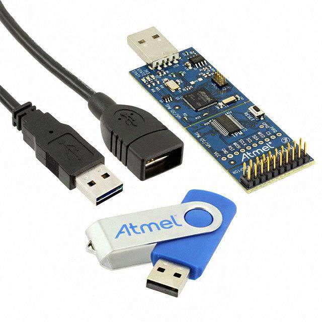
QF3DFX-DK USER’S GUIDE QF3DFX-DK Development Kit User’s Guide 1. Introduction The QF3DFX-DK Development Kit is a complete solution for evaluation and system development using the QF3DFX, a powerful 3-channel system-on-a-chip designed for seamless insertion in an audio serial data path. This User’s Guide describes the following: Kit Contents Installation Overview (Sections 3 – 4) Detailed Description of Operations (Sections 5 - 7) Reference (Sections 8 - 10) Note: There is a section index at the end of the document. The Quickfilter Pro software also features built-in help files. You can access them from within the program by clicking on “Help > Help Topics” at the top of the screen. Kit Contents Figure 1. QF3DFX-DK QF3DFX Development Board USB Cable Startup Guide Rev A6, March 2012 1 www.quickfiltertech.com
QF3DFX-DK USER’S GUIDE 2. Installation Please refer to the startup guide included in the kit. You should install the software first. This is available for free via download from: http://www.quickfiltertech.com/files/QFPRO_QF3DFX.exe Install it by double-clicking the downloaded file, and then plug in the board when prompted at the end of the install. Follow the prompts for installation of the USB drivers (Note: you have to go through the “Found new Hardware” wizard twice to install both A and B drivers) OVERVIEW 3. Opening Screen Double click on the “QFPro QF3DFX” icon on your desktop. The following screen appears: Figure 2. Dev Kit Functional Control Blocks and Basic User Interface This window is the main control point for configuring and using all aspects of the QF3DFX-DK development board. In the Controls/Status area are Bypass and Monitor buttons as well as Mute, Volume Up, Volume Down, and Profile - buttons that correspond to signals available as pushbutton inputs on the QF3DFX. Rev A6, March 2012 2 www.quickfiltertech.com
QF3DFX-DK USER’S GUIDE The button alternately enables and disables the QF3DFX to process the audio stream, as configured. When the Bypass button is blue, , the QF3DFX is bypassed and the audio passes through the QF3DFX unchanged. That is, the signal at dSDI passes unchanged to dSDO1, dSDO2, and dSDO3. When white, the QF3DFX performs all configured functions. The button alternately mutes and un-mutes the QF3DFX. When blue, , the QF3DFX is muted. Clicking on the button increments the volume by the amount called out by the next entry in the Volume Table. Clicking on the button decrements the volume by the amount called out by the previous entry in the Volume Table. The button will load the next (higher numbered) profile with each selection, rolling around to the first profile in a continuous loop. The button opens a window which provides a means to observe the real-time performance of any four of the functional blocks. While QFPro is running and connected to the QF3DFX-DK, the Mute, Volume Up, Volume Down, and Profile buttons are active and the corresponding physical buttons on the QF3DFX-DK are inactive. Clicking on one of these buttons in the QFPro window causes a corresponding effect on the audio: The Sample Frequency box displays the sampling frequency of 48000sps. The sample rate is currently fixed at 48000sps but will be variable in a future release Each of the functional blocks controls a feature inherent in the QF3DFX audio processor. A function can be alternately enabled or disabled with a single left-click of the mouse. When a block is pale in color, the respective function is disabled and data passes unaffected by the block. This is the default state for all blocks. When darker in color, the is enabled and the block’s function is applied to the incoming data. A right-click launches the appropriate dialog for setting the parameters of the selected block. When tuning in real-time, the dialog can remain visible and the parameters changed in real-time. When connected to the Quickfilter development board, the parameters values within a dialog are sent to the chip on the development board in real-time when either the pointer focus is moved from the changed parameter field or the Return/Enter key is pressed. The function blocks are color coded as follows: The pale yellow/orange blocks are global and can affect all 3 internal channels. The pale green/dark green blocks are Subwoofer/Center (Sw/Ce) blocks and affect the Sw/Ce channel only. The pale blue/dark blue blocks are Satellite blocks and affect both Satellite channels. Rev A6, March 2012 3 www.quickfiltertech.com
QF3DFX-DK USER’S GUIDE 4. Overview of Functional Control Blocks The QF3DFX is a 3-channel audio psychoacoustics, dynamic processing and filtering system (DPFS). The internal processing is achieved in a series of functional blocks. The mono channel is directed to a series of filters for band limiting and parametric equalization. The satellite channels pass through psychoacoustic effects and parametric equalization. All 3 channels converge at the Volume and Tone Control. The volume can be controlled externally via 3 pins, plus there is a provision for external amplifier thermal feedback. The graphical equalization can be externally controlled with one switch, PROFILES, with a provision for tone acknowledgement. Both the volume and graphical equalization can take on more elaborate forms of presentation in systems utilizing a controller. Dynamic bass, dynamic treble, soft signal management, and crossover filtering are available for the satellite channels. 4.1 Input/Output The Input / Output block is used to: Define the data source characteristics. Map the incoming data to the internal incoming channels. Map the internal outgoing channels to the output pins and slots The serial data interface can accept up to 2-channels of I2S or up to 8 slots of TDM source data which can be mixed to 1, 2 or 3 internal channels. For the I2S or TDM outputs, any of 5 internal channels (satellites crossed plus Sw/Ce) may be directed to any of the available 6 output I2S channels or 8 TDM channels including directing a single channel to all available channels. The amplitude of each the output channels can be independently adjusted. This amplitude can be negative allowing for the creation of digital differential outputs if required in the target system. 4.2 DC Blocking This is a fixed functional block and can be only enabled (on) or disabled (off). This bock affects all 3 internal channels. The structure is a classic 1st order leaky integrator high-pass filter set at 20 hertz with unity gain and shaping. For optimum performance of the AGC blocks at lower input levels, DC Blocking should be enabled. 4.3 Automatic Gain Control, AGC The function of the of the AGC is to keep the input signal energy between the high and low threshold values, each with programmable gain, attack time and release time. The satellite channels share common configuration settings and the Sw/Ce channel has independent settings. The attack time parameter controls how fast the signal is lowered when it is above high threshold while the release time parameter controls how fast the signal is raised when below the low threshold. The AGC can be programmed to ignore energy levels that are below the noise threshold value. The AGC is fully capable of supporting dynamic range compression and other similar features. The RMS averaging time is programmable to support special modes such as Night mode and Commercial mode Night mode prevents loud audio content when listening to audio at low levels. In that mode the AGC works to quickly reduce loud sounds only and does not increase quiet sounds. Commercial content often has a higher RMS value than the program content and is perceived as having more volume. The AGC works to quickly lower the commercial volume only without effecting program volume. Reference: Quickfilter’s QF3DFX-DK Tuning Guide. Rev A6, March 2012 4 www.quickfiltertech.com
QF3DFX-DK USER’S GUIDE 4.4 Subwoofer/Center Blocks The Sw/Ce blocks, one for Automatic Gain Control (AGC) and one for Parametric Equalization (PEQ), are used in processing a mono channel for subwoofer or center channel use. The Sw/Ce PEQ is comprised of 7 filters for band limiting and parametric equalization. The Sw/Ce AGC block output gain is independently adjustable for balancing with the satellite channel gain. QFpro’s parametric equalization design tool can be used to dynamically view composite results while selecting filter types and adjusting corresponding parameters. 4.5 High Frequency Restoration, HFR The HFR block restores high frequency content that has been lost due to audio compression or other processing. Most audio compression algorithms, such as MP3 encoding, limit the high frequency content. The function is highly programmable and common settings are utilized for both satellite channels. 4.6 Spatialization, SP The SP block uses a proprietary algorithm to enhance the sense of stereo separation in the audio signal. Many audio platforms have speakers that are in close proximity and therefore, do not have the desired stereo separation or a sense of spaciousness. The SP block enhances the stereo separation that is present in audio data to increase the apparent speaker separation. The SP function is highly configurable with fully independent filtering and amplitude parameters. 4.7 Virtual Bass, VB For speakers with limited low frequency response characteristics, the VB block adds more apparent bass using a propriety algorithm. The function is highly programmable using common coefficients for both satellite channels. 4.8 Parametric Equalization, PEQ The Parametric Equalizer is used to correct system and speaker related performance attributes and is comprised of 10 2nd-order biquad filters for use with the satellite channels (with common coefficients for both satellite channels) and 7 2nd- order biquad filters for use with the Subwoofer/Center channel. QFpro’s parametric equalization design tool can be used to dynamically view composite results while selecting filter types and adjusting corresponding parameters. 4.9 Volume and Tone Control, VTC The VTC comprises volume, mute and amplifier protection features for both the Satellite and Sw/Ce channels. Each of the three channels has an independent value and can be varied from +24 to –102 dB in linear increments of 1 dB steps, nonlinearly through a user programmable 100 step table or directly by a SPI or I2C bus master. The VTC block also includes user programmable slew rate to manage volume changes. Volume up, down and mute can be controlled from the pins. This method of controlling volume is useful if, for example, there is no external microcontroller in the system. Both pins are configured with an internal pull-up resistor. Therefore, the only external hardware required is a momentary switch that, when closed, will drive the pin level to ground. Internal logic provides a debounce function; there is no need for external debouncing circuitry. Holding either pin low, for the appropriate duration, will cause the gain to change repeated up or down, as appropriate. Forcing the volume up and down pins low simultaneously will mute all three channels. An amplifier protection pin is provided to aid in the protection of amplifiers that don’t have strong thermal or other protection from very loud signals. If the pin is held low for at least 30 ns, the volume is decrease by 3dB. The reduced volume will remain until the device is reset. This feature utilizes the volume slew feature and therefore, the volume change will not be abrupt. Rev A6, March 2012 5 www.quickfiltertech.com
QF3DFX-DK USER’S GUIDE 4.10 5-Band Graphic Equalizer, GEQ The GEQ is a 5-band graphic equalizer that can be controlled by the end user. Each of the parallel bands is composed of a 2nd order filter and can be independently varied from +12 to –12dB by the profile pin or directly by a SPI or I2C bus master. The end user can control the GEQ by choosing one of several profiles. The profiles are a set of coefficients for the filters that produce a certain shape in the frequency response of the GEQ. This method of controlling volume is useful if there is no external microcontroller in the system. Each time the profile pin is momentarily toggled low, the profile advances in a round-robin fashion. The profile pin is configured similar to the volume pins described above. There is an option for a unique tone to be generated for each profile thereby providing the end user with a low cost indication of the profile selected. A dedicated internal memory structure is utilized for coefficient storage of up to 8 profiles. 4.11 Dynamic Bass and Dynamic Treble, DB & DT Dynamic bass compensate for the difficulty in hearing bass as the volume is decreased. The DB block compensate for this by boosting lower frequencies as their energy level or amplitude decreases. Dynamic treble compensates for higher frequency content that drops below a relative reference. The DT block will boost the higher frequencies. Dynamic bass and dynamic treble can be independently enabled and are highly programmable with respect to operating frequency range and corresponding amplitudes. 4.12 Crossover, CO The CO block will split each input channel into two audio frequency bands by use of a high pass filter and a low pass filter. This allows the user to better match the low and high frequencies to the speakers (i.e., woofers and tweeters). The block is comprised of a 4th-order filter capable of numerous types of crossover structures including the classic Linkwitz-Riley filter, which is the default. 4.13 Soft Clipper, SC The SC block is a non-abrupt waveform modification technique used to manage signal amplitudes on a sample by sample basis in order to prevent the hard clipping of the audio. 4.14 Configuration Interface, CI The Configuration interface is used to read and write the control registers and program the coefficient memory space and supports both I2C and SPI protocols. I2C can be a master and a slave while SPI operates only in slave mode. Both protocols can be used simultaneously within a system. There are 2 address pins available for I2C system requirements. The configuration interface supports self-booting (configure and run) from an external I2C EEPROM. The EEPROM is also utilized to save user-controlled settings for reinstatement at power up (previous values for volume and profile). Multiple QF3DFX devices can share a common EEPROM The external I2C EEPROM can be either an 8 or 16 bit format device. The SPI Interface is capable of operating up to 20MHz, while the I2C interface can run up to 400 kHz. Both interfaces can run at much slower speeds. Rev A6, March 2012 6 www.quickfiltertech.com
QF3DFX-DK USER’S GUIDE DETAILED DESCRIPTION OF OPERATIONS 5. Global Controls The Global Control functions affect all audio channels, both of the satellite channels as well as the subwoofer/center channel. 5.1 Input/Output Serial audio streams of 16 or 24 bit data of I2S, Left Justified, Right Justified or TDM are supported. The IDF block creates 3-channels of audio data from either I2S (2 channels) or up to 8 channels of TDM. For I2S data, the 2 satellite channels are summed and reduced, as programmed by the user, to form the 3rd channel. For TDM data, any of the channels within the TDM stream can be mixed and reduced to any of the 3 block output channels (2 satellites and 1 subwoofer/center channels). The satellite channels use common settings. The serial audio data can be in 2’s complement or offset binary format with MSB first. Multiple QF3DaFX’s can be utilized in series to process all the of TDM channels utilizing either TDM or I2S outputs The QF3DaFX utilizes the incoming bit clock and framing signal to exit power down mode and process the incoming serial audio data stream. The QF3DaFX returns to power down mode when these are not active. If desired, the QF3DaFX can be bypassed. The bypass function simply routes the input to the appropriate output. To configure the Input/Output controls, right-click on the function block, which launches this screen: Figure 3. Input/Output Controls Rev A6, March 2012 7 www.quickfiltertech.com
QF3DFX-DK USER’S GUIDE Details Data Configuration: - Data Mode can be I2S, Left Justified, Right Justified, or TDM. - Data Format can be either 2’s Complement or Offset Binary. - Data Select Polarity allows a choice of Active High or Active Low. - Data Clock Polarity allows a choice of Active High or Active Low. Data and Frame Size: - Data Size can be either 16 bits or 24 bits. - Frame Size can be any value between 32 and 256 (inclusive). - The Unassigned Slots option is available only when the Data Mode selection is TDM. All unassigned TDM slots can be set to either pass-through or tri-state. Input Assignment and Scaling: - There are 3 internal channels assignments available at the input. - Satellite 1 (Sat-1), Satellite 2 (Sat-2) and Subwoofer/Center (Sw/Ce). - Any combination of inputs can be scaled and assigned to an internal channel. - Assignment is accomplished by placing the appropriate scaling coefficient in the appropriate field in the Input table. Output Assignment: - Satellite channels can be split in to high and low channels; Sat-1-high, Sat1/Sat-1-low, Sat-2-high and Sat2/Sat- 2-low. - There can be up to 5 internal channels assignments available at the output. - Assignment is accomplished by making the desired selection from the appropriate drop-down field in the Output table. - Any of the internal channels can be assigned to any output channel or multiple outputs channels to a maximum of 5 assignments. Output Scaling and Polarity: - The internal channels can be scaled by entering scaling values in their respective fields. These can range from +60dB to -72dB. - Digital differential output can be achieved by choosing a negative coefficient vale. 5.2 DC Blocking This block provides the classic audio DC blocking filtering and is used to meet the overall system DC blocking rejection requirements. Right-clicking on the function block brings up this screen: Rev A6, March 2012 8 www.quickfiltertech.com
QF3DFX-DK USER’S GUIDE Figure 4. DC Blocking Window Details This is a fixed functional block and can be only enabled (on) or disabled (off). This bock affects all 3 internal channels. The structure is a classic 1st order leaky integrator high-pass filter set at 20 hertz with unity gain and shaping. For optimum performance of the psychoacoustic blocks, subsonic filtering is accomplished using the available filters within the parametric equalization blocks. DC Blocking can be alternately enabled and disabled by left-clicking the function block. When enabled the block is orange: 5.3 Volume and Tone Control, VTC The VTC comprises volume, mute, loudness and amplifier protection features for both the satellite and Sw/Ce channels. Each of the three channels has a single value and can be varied from +24dB to –96 dB (including mute) in linear increments of 1.5 dB steps, nonlinearly through a user programmable 100 step table or directly by a SPI or I2C bus master. The VTC block also includes user programmable slew rate to manage volume changes. Volume up, down and mute can be controlled from the pins. This method of controlling volume is useful if, for example, there is no external microcontroller in the system. Both pins are configured with an internal pull-up resistor. Therefore, the only external hardware required is a momentary switch that, when closed, will drive the pin level to ground. Internal logic provides a debounce function; there is no need for external debouncing circuitry. Holding either pin low, for the appropriate duration, will cause the gain to change repeated up or down, as appropriate. Forcing the volume up and down pins low simultaneously will mute all three channels. An amplifier protection pin is provided to aid in the protection of amplifiers that don’t have strong thermal or other protection from very loud signals. If the pin is held low for at least 30 ns, the volume is decrease by a user selectable value ranging from 0dB to 31dB.. The reduced volume will remain in effect until the device is reset. This feature utilizes the volume slew feature and therefore, the volume change will not be abrupt. To configure the Volume Control options, right-click the function block, which brings up this screen: Rev A6, March 2012 9 www.quickfiltertech.com
QF3DFX-DK USER’S GUIDE Figure 5. Volume and Tone Control Window Details The Volume and Tone Control affects the level of all internal channels. Volume Control: - The volume is controlled nonlinearly through a user programmable 100 step table (or directly by a SPI or I2C bus master). A custom Volume Table can be used and is accessed and brought into the configuration via the Open File button. - The Max Index Used in Volume Table is selected by entering the desired value in the field. This determines the last value used in the table. - The Initial Index Used in Volume Table determines the first value used in the table. The range of adjustment of the volume will move between the initial and max table entries. - Slew Rate of the Volume is selected by the drop-down field and sets the rate at which the volume moves between values as it’s changed. - The Amplifier Protection Amount – If not set to zero, this enables the Amplifier Protection Pin. The pin is level- based and, when active (refer to the datasheet), the volume will be decreased by the value indicated and held until the pin is no longer active. When released (becomes inactive), the volume will return to its previous value. Tone Control: - The check boxes enable the tone feedback beep for Profile, Volume Up, Volume Down, Volume Sustain, and Mute. Select any mix of the 5 options. Volume sustain is when the volume pin is held active versus a momentary pulse. - The Gain and Frequency of two tones can be individually set. Rev A6, March 2012 10 www.quickfiltertech.com
QF3DFX-DK USER’S GUIDE When enabled the block is orange: 6. Subwoofer/Center Controls The Subwoofer/Center Control functions affect only the Subwoofer/Center channel. 6.1 Automatic Gain Control, AGC The function of the of the AGC is to keep the input signal energy between the high and low threshold values, each with programmable gain, attack time and release time. The Sw/Ce channel has AGC settings that are independent of the satellite channels’ settings. The attack time parameter controls how fast the signals are lowered when the AGC output sample value is above the high threshold. The release time parameter controls how fast the signal is raised when the average AGC output energy is below the low threshold. The AGC gain can be programmed to ignore input energy levels that are below the noise threshold value. The AGC is fully capable of supporting dynamic range compression. The RMS averaging time is programmable to support special modes such as Night mode and Commercial mode Night mode prevents loud audio content when listening to audio at low levels. The AGC works to quickly reduce loud sounds only and does not increase quiet sounds. Commercial content has a higher RMS value than the program content and is perceived as having more volume. The AGC works to quickly lower the commercial volume only without effecting program volume. To configure the Subwoofer/Center AGC functions, right-click the function block; this brings up this screen: Rev A6, March 2012 11 www.quickfiltertech.com
QF3DFX-DK USER’S GUIDE Figure 6. Sub-Woofer/Center AGC Controls The threshold values are illustrated in this diagram: Figure 7. AGC Thresholds Details T – The High Threshold value which should be set to the maximum desired signal peaks as the AGC will attempt to keep h the signal below this level. This value is between T and 0dB. This comparison is between the High Threshold and AGC l Output instantaneous sample values. T – The Low Threshold value which should be less than T and more than T . The AGC will keep the output average l h n energy above this level. This value is between T and T . This comparison is between the Low Threshold and the AGC n h Output average energy. T – The Noise Threshold value which should be less than T. The AGC will assume input energy levels below this n l threshold are noise and will ignore them. This value is between 0-120 dB and T. This comparison is between the Noise l Threshold and the AGC Input average energy. Ac – The Attack Coefficient parameter controls how fast the signal is lowered when the attack function is being applied. The attack coefficient is typically larger than the release coefficient. Rc – The Release Coefficient parameter controls how fast the signal is raised when the release function is being applied. Averaging Coefficient (Alpha) - The RMS energy of both the input and output signals is estimated (independently) using a first order IIR filter that averages each signal. The length of the average is controlled by an averaging coefficient, Alpha. Higher values of Alpha produce shorter averages; lower values produce longer averages. If the average is very long, the AGC will be responding to longer term level changes. If the average is very short, the AGC will make changes based on very short energy bursts (of as low as two or three samples). The smaller the Alpha value, the longer the averaging period. Automatic Gain Control can be enabled and disabled by left-clicking the function block. When enabled the block is dark green: 6.2 Parametric Equalization, PEQ The Parametric Equalizer is used to correct system and speaker related performance attributes and is comprised of 7 2nd- order biquad filters for use with the Subwoofer/Center channel. Rev A6, March 2012 12 www.quickfiltertech.com
QF3DFX-DK USER’S GUIDE QFpro’s parametric equalization design tool can be used to dynamically view composite results while selecting filter types and adjusting corresponding parameters. To configure the Subwoofer/Center PEQ function, right-click the function block, which brings up the following screen: Figure 8. PEQ Control Window Details A cascade of 7 2nd-order filters is available for general use. The graphs, one for Magnitude and one for Phase, will display the composite results for the enabled filters. Filters are enabled (on) and disabled (off) by selecting the check box on the left of each filter. Filter Type –select from the list of available filter types – Bypass, Peaking, High Shelf, Low Shelf and Custom. The Table option allows the user to either enter the coefficient directly or a text file containing the coefficients. See the Main Window Help for further information on the text file format. Frequency – is the knee or center point of the filter type selected. Q Factor – The filters have a Q setting that defines their response pattern. The optimal Q is 0.707; lower values result in a flatter (wider) response and higher values result in a peaked (narrower) response. Boost - is used to adjust the resulting level of the individual band. Custom Filter – browse to the text file containing the custom coefficients. Block Gain - is used to adjust the resulting level of the entire block. Rev A6, March 2012 13 www.quickfiltertech.com
QF3DFX-DK USER’S GUIDE Parametric Equalization can be enabled and disabled by left-clicking the function block. When enabled the block is dark green: 7. Satellite Controls The Satellite Control functions affect both satellite channels. 7.1 Automatic Gain Control, AGC The function of the of the AGC is to keep the input signal energy between the high and low threshold values, each with programmable gain, attack time and release time. The satellite channels share common configuration settings. The same gain value is applied to both the left and right channels at all times. The attack time parameter controls how fast the signals are lowered when either left or right channel’s sample value is above the high threshold. The release time parameter controls how fast the signals are raised when below their both of their average energies are below the low threshold. The AGC gain can be programmed to ignore input energy levels that are below the noise threshold value. The AGC is fully capable of supporting dynamic range compression. The RMS averaging time is programmable to support special modes such as Night mode and Commercial mode Night mode prevents loud audio content when listening to audio at low levels. The AGC works to quickly reduce loud sounds only and does not increase quiet sounds. Commercial content has a higher RMS value than the program content and is perceived as having more volume. The AGC works to quickly lower the commercial volume only without effecting program volume. To configure the Satellite AGC functions, right-click the function block; this brings up this screen: Rev A6, March 2012 14 www.quickfiltertech.com
QF3DFX-DK USER’S GUIDE Figure 9. Satellite AGC Controls The threshold values are illustrated in this diagram: Figure 10. AGC Thresholds Details The setting here are common to both Satellite channels T – The High Threshold value which should be set to the maximum desired signal peaks as the AGC will attempt to keep h the signal below this level. This value is between T and 0dB. This comparison is between the High Threshold and AGC l Output instantaneous sample values. T – The Low Threshold value which should be less than T and more than T . The AGC will keep the output average l h n energy above this level. This value is between T and T . This comparison is between the Low Threshold and the AGC n h Output average energy. T – The Noise Threshold value which should be less than T. The AGC will assume input energy levels below this n l threshold are noise and will ignore them. This value is between 0-120 dB and T. This comparison is between the Noise l Threshold and the AGC Input average energy. Rev A6, March 2012 15 www.quickfiltertech.com
QF3DFX-DK USER’S GUIDE Ac – The Attack Coefficient parameter controls how fast the signal is lowered when the attack function is being applied. The attack coefficient is typically larger than the release coefficient. Rc – The Release Coefficient parameter controls how fast the signal is raised when the release function is being applied. Averaging Coefficient (Alpha) - The RMS energy of both the input and output signals is estimated (independently) using a first order IIR filter that averages each signal. The length of the average is controlled by an averaging coefficient, Alpha. Higher values of Alpha produce shorter averages; lower values produce longer averages. If the average is very long, the AGC will be responding to longer term level changes. If the average is very short, the AGC will make changes based on very short energy bursts (of as low as two or three samples). The smaller the Alpha value, the longer the averaging period. Automatic Gain Control can be enabled and disabled by left-clicking the function block. When enabled the block is dark blue: 7.2 High Frequency Restoration, HFR The High Frequency Restoration (HFR) block attempts to restore any high frequency content that has been lost due to audio compression or other processing. Most audio compression algorithms, such as that used with MP3 encoding, limit the high frequency content in order to reduce bit rates. The high frequencies can be limited as low as 10 kHz, for low bit rate compressed audio. The HFR block attempts to restore these lost frequencies. The HFR block can also be used on full-band audio to emphasize high frequency content, to compensate for speaker performance, as a system designer preference or to satisfy market requirement. Common coefficients are utilized for both satellite channels. The function is highly programmable including gain control for mixing the resulting effect back with the primary audio data. To configure the HFR function, right-click the function block, which brings up this screen: Figure 11. HFR Controls Rev A6, March 2012 16 www.quickfiltertech.com
QF3DFX-DK USER’S GUIDE Details Quickfilter proprietary high frequency restoration psychoacoustic effect restores content where none currently exists. The lost content can be from any source and the result of any cause (e.g., such as compression). Audio content, when displayed with linear frequency on an amplitude-frequency graph, typically displays as decreasing levels with increasing frequency. Slope Parameter – To maintain a typical audio shape, as described above, a low-pass filter is available as a 1st order (10dB/decade) or 2nd order (20dB/decade) slope. Used with Gain, to control the shape of the mixed-in effect. 1 represents a shallow slope and 2 represents a steeper slope. Mix-in Frequency – Typically set at the end point of source content (beyond which point there is no source content) but can be set as preferred. Gain – The amount of gain applied to the new content prior to its addition to the audio stream. High Frequency Restoration can be enabled and disabled by left-clicking the function block. When enabled the block is dark blue: 7.3 Spatialization, SP The SP block uses a proprietary algorithm to enhance the sense of stereo separation in the audio signal. Many audio platforms have speakers that are in close proximity and therefore, do not have the desired stereo separation or a sense of spaciousness. The SP block enhances the stereo separation that is present in audio data to increase the apparent speaker separation. The Spatialization function is highly configurable with fully independent common (sum) and side (difference) processing for audio separation enhancement. The common and side signals can be filtered and amplitude adjusted. In addition, the side signals, left side and right side, can also have a delay component. To configure the Spatialization function, right-click the function block, which brings up this screen: Rev A6, March 2012 17 www.quickfiltertech.com
QF3DFX-DK USER’S GUIDE Figure 12. Spatialization Controls Details The block derives its effect from the source and them mixes the results to become the source going forward. Reference the tuning guide for additional information on how to tune this feature. Source Path Gain – sets the amount of the original source audio to be mixed back with the effect. This path is unchanged by the Spatialization effect. Source Filter Type – can be used to band-limit or “color” the effect using a high-pass or low-pass filter. It can also be bypassed. Source Path Cut-Off Frequency – the transition frequency for the selected filter if not bypassed. Effect Path Gain – sets the amount of the Effect Path audio to be mixed with the source. Effect Filter Type – can be used to band-limit or “color” the effect using a high-pass or low-pass filter. It can also be bypassed. Effect Path Cut-Off Frequency – the transition frequency for the selected filter if not bypassed. Enhance Spatial Effect – additional SP effect can be generated by enabling this feature (on). This can be helpful when the source material has limited unique channel content. Spatialization can be enabled and disabled by left-clicking the function block. When enabled the block is dark blue: 7.4 Virtual Bass, VB With smaller enclosures come corresponding smaller speakers which do not reproduce bass frequencies well. By using Quickfilter’s VB effects block, more apparent bass can be added to the satellite channels. Common coefficients are utilized for both satellite channels. The function is highly programmable including gain control for mixing the resulting effect back with the primary audio data. To configure the Virtual Bass function, right-click the function block, which brings up this screen: Rev A6, March 2012 18 www.quickfiltertech.com
QF3DFX-DK USER’S GUIDE Figure 13. Virtual Bass Controls Details The block derives its effect from the source and them mixes the results back with the source. Reference the tuning guide for additional information on how to tune this feature. Bass Frequency – is the point in the target speaker transfer function where audible bass begins. Effect – there are two propriety methods available for this effect. Type 1 has less effect. Type 2 has more effect. Gain – sets the amount of gain applied to the effect prior to mixing back with the source. Virtual Bass can be enabled and disabled by left-clicking the function block. When enabled the block is dark blue: 7.5 Parametric Equalization, PEQ The Parametric Equalizer is used to correct system and speaker related performance attributes and is comprised of 10-2nd order biquad filters with common coefficients for satellite channels. QFPro’s parametric equalization design tool can be used to dynamically view composite results while selecting filter types and adjusting corresponding parameters. To configure the Parametric Equalization function, right-click the function block, which brings up this screen: Rev A6, March 2012 19 www.quickfiltertech.com
QF3DFX-DK USER’S GUIDE Figure 14. Satellite PEQ Control Window Details A cascade of 10 2nd-order filters is available for general use. The graph will display the composite results, for both Magnitude and Phase, for the enabled filters. Filters are enabled by selecting a filter type from the drop-down box associated with each band. Filter Type –select from the list of available filter types – Peaking, High Shelf, Low Shelf, and Custom. The Custom option allows the user to enter the filter coefficients by selecting, via the Open File buttons, a text file containing the coefficients. See the Main Window Help for further information on the test file format. Frequency – is the knee or center point of the filter type selected. Q Factor – The filters have a Q setting that defines their response pattern. The optimal Q is 0.725; lower values result in a flatter (wider) response and higher values result in a peaked (narrower) response. Boost - is used to adjust the resulting level of the individual band. Custom Filter – browse to the text file containing the custom coefficients. Block Gain - is used to adjust the resulting level of the entire block. Parametric Equalization can be enabled and disabled by left-clicking the function block. When enabled the block is dark blue: 7.6 Graphic Equalization, GEQ The GEQ is a 5 band graphic equalizer that can be controlled by the end user. Each of the parallel bands is composed of a 2nd order filter and can be independently varied from +15dB to –15dB by the profile pin or directly by a SPI or I2C bus master. Rev A6, March 2012 20 www.quickfiltertech.com
QF3DFX-DK USER’S GUIDE The end user can control the GEQ by choosing one of several profiles. The profiles are a set of coefficients for the filters that produce a certain shape in the frequency response of the GEQ. This method of controlling volume is useful if there is no external microcontroller in the system. Each time the profile pin is momentarily toggled low, the profile advances in a round-robin fashion. The profile pin is configured similar to the volume pins described above. To configure the Graphic Equalization function, right-click the function block, which brings up this screen: Figure 15. Graphic Equalizer Control Window Details 5 parallel 2nd-order filters are available for up to 8 profiles. The graph will display the shape for the selected profile. Filter Type – Select the filter type desired or bypass. Filter 1 options are lowpass or bandpass. Filter 5 options are highpass or bandpass. Filters 2,3,4 can be bandpass only. Center Frequency – the band’s center frequency is entered directly. Q – the band’s bandwidth is entered directly. Profile Gains – enter the amount of gain for each filter used in the given profile. Max Profile – profiles are enabled by entering the number of profiles used in the Max Profile field. Note: the profiles MUST be enabled contiguously – without gaps – as the number available is determined by the value in the Max Profile field. Graphic Equalization can be enabled and disabled by left-clicking the function block. When enabled the block is dark blue: 7.7 Dynamic Bass, DB Rev A6, March 2012 21 www.quickfiltertech.com
QF3DFX-DK USER’S GUIDE Dynamic bass compensates for the difficulty in hearing bass as the volume is decreased. The DBT block compensate for this by boosting lower frequencies as their energy level or amplitude decreases. Dynamic bass and dynamic treble can be independently enabled and are highly programmable with respect to operating frequency range and corresponding amplitudes. To configure the Dynamic Bass function, right-click the function block, which brings up this screen: Figure 16. Dynamic Bass Controls Details This effect maintains a constant bass level. Upper Frequency – is the upper bound of where the effect will be applied. High Threshold – above this level, no effect is applied. Below this level, the degree of effect applied is per the Tracking Rate selected. Noise Threshold – below this level no effect is applied. Tracking Rate – the degree of effect applied: 100 % - for every 1 dB of reduction, the gain in increased 1 dB until the Max Gain is reached 75% - for every 1 dB of reduction, the gain in increased 0.75 dB until the Max Gain is reached 50 % - for every 1 dB of reduction, the gain in increased 0.5 dB until the Max Gain is reached 25 % - for every 1 dB of reduction, the gain in increased 0.25 dB until the Max Gain is reached Maximum Gain – the maximum allowable gain that Tracking can achieve. Dynamic Bass can be enabled and disabled by left-clicking the function block. When enabled the block is dark blue: Rev A6, March 2012 22 www.quickfiltertech.com
QF3DFX-DK USER’S GUIDE 7.7 Dynamic Treble, DT Dynamic treble compensates for higher frequency content that drops below a relative reference. The BDT block will boost the higher frequencies. Dynamic bass and dynamic treble can be independently enabled and are highly programmable with respect to operating frequency range and corresponding amplitudes. To configure the Dynamic Treble function, right-click the function block, which brings up this screen: Figure 17. Dynamic Treble Controls Details This effect maintains a constant treble level. Lower Frequency – is the lower bound of where the effect will be applied. High Threshold – above this level, no effect is applied. Below this level the degree of effect applied is per the Tracking Rate selected. Noise Threshold – below this level no effect is applied. Tracking Rate – the degree of effect applied 100 % - for every 1 dB of reduction, the gain in increased 1 dB until the Max Gain is reached 75% - for every 1 dB of reduction, the gain in increased 0.75 dB until the Max Gain is reached 50 % - for every 1 dB of reduction, the gain in increased 0.5 dB until the Max Gain is reached 25 % - for every 1 dB of reduction, the gain in increased 0.25 dB until the Max Gain is reached Maximum Gain – the maximum allowable gain that Tracking can achieve. Dynamic Treble can be enabled and disabled by left-clicking the function block. When enabled the block is dark blue: Rev A6, March 2012 23 www.quickfiltertech.com
QF3DFX-DK USER’S GUIDE 7.8 Crossover The Crossover block provides either a classic 4th-order Linkwitz-Riley or a custom, user-defined crossover. The Crossover block will split each input channel into two audio frequency bands by use of a high pass filter and a low pass filter. This allows the user to better match the low and high frequencies to the speakers (i.e., woofers and tweeters). To configure the Crossover function, right-click the function block, which brings up this screen: Figure 18. Crossover Controls Details This effect maintains a constant treble level. Filter Type – Select either Linkwitz-Riley or Custom. Crossover Frequency – If the Linkwitz-Riley filter type is selected, then this is the 3dB corner frequency for both filters. Low Pass Custom – Use the Open File button to browse to the file defining the custom low pass filter. High Pass Custom – Use the Open File button to browse to the file defining the custom high pass filter. Lowpass Gain – Passband gain for the low pass filter. Highpass Gain – Passband gain for the high pass filter. The Crossover can be enabled and disabled by left-clicking the function block. When enabled the block is dark blue: Rev A6, March 2012 24 www.quickfiltertech.com
QF3DFX-DK USER’S GUIDE 7.9 Soft Clipper The Soft Clipper block is a non-abrupt waveform modification technique used to manage signal amplitudes on a sample by sample basis in order to prevent the hard clipping of the audio. To configure the Soft Clipper function, right-click the function block, which brings up this screen: Figure 19. Soft Clipper Controls Details Compression Amount – The amount of compression for signals above the Threshold. Threshold – The level above which the effect is applied. The Soft Clipper can be enabled and disabled by left-clicking the function block. When enabled the block is dark blue: Rev A6, March 2012 25 www.quickfiltertech.com
QF3DFX-DK USER’S GUIDE REFERENCE 8. External Connections This section provides more details of interconnects within the development board and to the expansion headers. Figure 45 shows a global view of all connections. Figure 20. QF3DFX-DK Main Features Expansion Connectors J2 is used to connect an Altera ByteBlaster cable in order to program the Cyclone II FPGA. This is reserved for internal use. J7 is used to connect to an external TDM source and/or sink. It can be used to connect multiple QF3DFX-DK boards in order to implement and test 5.1 and 7.1 stereo system implementations. J8 and J9 are used to interface the QF3DFX-DK to a QF3DFX on an external target board. J8 allows the pushbuttons on the QF3DFX-DK to signal the external part. J9 interfaces all other control signals necessary for the operation of the external QF3DFX. The use of these two connectors allows the QF3DFX-DK to fully control the external QF3DFX (assuming the external target board has been designed with this functionality in mind) while providing the full functionality of the QFPro software to build, test, and evaluate the performance on the target board. Rev A6, March 2012 26 www.quickfiltertech.com
QF3DFX-DK USER’S GUIDE Audio Connectors The input and output audio connector level switch positions, Toward audio connect position o Input: 2Vpp o Outputs: 1Vpp Away audio connect position o Input: 1Vpp o Outputs: 2Vpp External Power, Connector J3 The development board is usually powered via the USB connection on J1 and features on-board voltage regulators to provide a clean supply. External power can be used to power the board via connector J3, independent of the USB. In this Stand-Alone Mode, the board will boot from the onboard EEPROM. This mode is useful for testing filter configurations with the QF3DFX-DK embedded in a prototype or test product. When powered only by the USB interface the EEPROM is not used to initialize the board – the board is initialized by QFPro via the USB interface. However, QFPro is used to load the EEPROM with whatever configuration (up to four configurations can be held in the EEPROM) is desired. Once the EEPROM is loaded via QFPro, any subsequent power-up using an external power supply will result in the stored configuration being active. Booting into Stand-Alone Mode The QF3DFX-DK can self-boot into Stand-Alone mode using any of the four stored configurations. By default, the QF3DFX-DK will boot into Stand-Alone mode using Configuration #1 when powered up with no USB cable connected. To boot from a designated configuration: 1. Press and hold down MUTE 2. Press and Release the following a. Configuration #1: VUP b. Configuration #2: VDN c. Configuration #3: PROF d. Configuration #4: VUP and VDN (at the same time) 3. Release MUTE After you have released MUTE, the QF3DFX-DK will reboot and light LED’s in this manner (the Green LED is always lit): CFG1 CFG2 CFG3 CFG4 Rev A6, March 2012 27 www.quickfiltertech.com
QF3DFX-DK USER’S GUIDE Note: It is important to follow the recommended procedure, described below, when entering Stand-Alone Mode. Procedure for Entering Stand-Alone Mode 1. Write the configuration to EEPROM. 2. Mute the audio source on the input channel. 3. Power off the audio units on the output channels. 4. Exit QFPro. 5. Unplug the USB cable. 6. Disconnect the audio inputs and outputs. 7. Ensure that the audio input source and audio output sinks to be used in stand-alone mode are power off. 8. Connect the board to the audio inputs and outputs to be used in stand-alone mode. 9. Apply power to the QF3DFX-DK. 10. Power up the audio inputs and outputs. This can be simultaneous with powering the QF3DFX-DK. 11. End of Procedure. NOTE: If the USB interface is to be used, then, for correct operation, the external power source should be disconnected prior to connecting the USB cable. Test Points A number of test points are provided for your convenience. Please refer to the schematics for their location and connection. 8.1 Programming a QF3DFX on a Target Board QF3DFX-DK Target QF3DFX J9 1 2 4 SPI_SCLK 7 cSCK 6 SPI_MOSI 24 cSDI 8 cSDO_EXT 14 cSDO 9 10 QF3DFX_CS_EXT 1 cCSn 11 GND 13GND QF3DFX_RESET 5 RSTn Figure 21. External Target Connection Rev A6, March 2012 28 www.quickfiltertech.com
QF3DFX-DK USER’S GUIDE 8.2 TDM Interface QF3DFX-DK J7 TDM_DATA_OUT3 2 1 TDM_DATA_OUT2 3 TDM_DATA_OUT 5 TDM_SYNC 7 TDM_CLK 9 TDM_DATA_IN Figure 22. TDM Connection 8.3 External Pushbutton Control QF3DFX-DK 3.3V_Audio 3V3 J8 1V8 2 1 Profile_Signal NC 3 5 MUTE 7 VUP 9 VDN NC 11 13 AMP NC 15 Figure 23. External Pushbutton Control Rev A6, March 2012 29 www.quickfiltertech.com
QF3DFX-DK USER’S GUIDE 8.4 FPGA Programming The FPGA Programming connector, J2, is reserved for internal use only. 8.5 EEPROM Programming 9. Configuration Files Quickfilter Pro saves configuration files with a .q1d2 suffix. But what exactly is a configuration file? How is it different from an image file? Two of the main functions of Quickfilter Pro are: Collect user inputs for the device configuration for a specific application and convert this to suitable register configurations, and, Take user specified filter parameters (sampling rate, roll off frequencies, attenuation etc) and convert this to the corresponding filter coefficients. The resulting set of register values and filter coefficients is called an image (see Section 16). Figure 24. Configuration Relationships When Quickfilter Pro saves a configuration file it includes all the user-specified parameters as well as the resulting register values and coefficient values (Figure 24). This allows you to load a configuration for editing and already have all your original user inputs in place. When you export an image, Quickfilter Pro extracts just the register values, volume table values, and coefficient values for output. Rev A6, March 2012 30 www.quickfiltertech.com
QF3DFX-DK USER’S GUIDE 10. Development Board Schematics Full schematics for the QF3DFX-DK can be found in the documents folder created during the Quickfilter Pro install (C:\Program Files\Quickfilter Technologies\QF3DFX\Documents). For your convenience you can open this folder from within the program by clicking on Help in the menu bar. The schematics can be found in the file name that begins QF3DFX-DK-Schematics. Rev A6, March 2012 31 www.quickfiltertech.com
QF3DFX-DK USER’S GUIDE Section Index 1. INTRODUCTION ...................................................................................................................................................................... 1 2. INSTALLATION ....................................................................................................................................................................... 2 3. OPENING SCREEN ................................................................................................................................................................. 2 4. OVERVIEW OF FUNCTIONAL CONTROL BLOCKS ...................................................................................................................... 4 4.1 INPUT/OUTPUT .................................................................................................................................................................... 4 4.2 DC BLOCKING ..................................................................................................................................................................... 4 4.3 AUTOMATIC GAIN CONTROL ................................................................................................................................................ 4 4.4 SUBWOOFER/CENTER BLOCKS ............................................................................................................................................ 5 4.5 HIGH FREQUENCY RESTORATION, HFR ................................................................................................................................ 5 4.6 SPATIALIZATION, SP............................................................................................................................................................ 5 4.7 VIRTUAL BASS, VB ............................................................................................................................................................. 5 4.8 PARAMETRIC EQUALIZATION, PEQ ...................................................................................................................................... 5 4.9 VOLUME AND TONE CONTROL, VTC ..................................................................................................................................... 5 4.10 5-BAND GRAPHIC EQUALIZER, GEQ .................................................................................................................................. 6 4.11 DYNAMIC BASS AND DYNAMIC TREBLE, DB & DT .............................................................................................................. 6 4.12 CROSSOVER, CO .............................................................................................................................................................. 6 4.13 SOFT CLIPPER, SC ............................................................................................................................................................ 6 4.14 CONFIGURATION INTERFACE, CI ......................................................................................................................................... 6 5. GLOBAL CONTROLS .............................................................................................................................................................. 7 5.1 INPUT/OUTPUT .................................................................................................................................................................... 7 5.2 DC BLOCKING ..................................................................................................................................................................... 8 5.3 VOLUME AND TONE CONTROL, VTC ..................................................................................................................................... 9 6. SUBWOOFER/CENTER CONTROLS ........................................................................................................................................ 11 6.1 AUTOMATIC GAIN CONTROL, AGC ..................................................................................................................................... 11 6.2 PARAMETRIC EQUALIZATION, PEQ .................................................................................................................................... 12 7. SATELLITE CONTROLS ......................................................................................................................................................... 14 7.1 AUTOMATIC GAIN CONTROL, AGC ..................................................................................................................................... 14 7.2 HIGH FREQUENCY RESTORATION, HFR .............................................................................................................................. 16 7.3 SPATIALIZATION, SP.......................................................................................................................................................... 17 7.4 VIRTUAL BASS, VB ........................................................................................................................................................... 18 7.5 PARAMETRIC EQUALIZATION, PEQ .................................................................................................................................... 19 7.6 GRAPHIC EQUALIZATION, GEQ .......................................................................................................................................... 20 7.7 DYNAMIC BASS, DB .......................................................................................................................................................... 21 7.7 DYNAMIC TREBLE, DT ....................................................................................................................................................... 23 7.8 CROSS-OVER .................................................................................................................................................................... 24 7.9 SOFT CLIPPER................................................................................................................................................................... 25 8. EXTERNAL CONNECTIONS .................................................................................................................................................... 26 8.1 PROGRAMMING A QF3DFX ON A TARGET BOARD .............................................................................................................. 28 8.2 TDM INTERFACE ............................................................................................................................................................... 29 8.3 EXTERNAL PUSHBUTTON CONTROL ................................................................................................................................... 29 8.4 FPGA PROGRAMMING ....................................................................................................................................................... 30 8.5 EEPROM PROGRAMMING ................................................................................................................................................ 30 9. CONFIGURATION FILES ........................................................................................................................................................ 30 10. DEVELOPMENT BOARD SCHEMATICS .................................................................................................................................. 31 Rev A6, March 2012 32 www.quickfiltertech.com
QF3DFX-DK USER’S GUIDE Contact Information: Quickfilter Technologies, Inc. 1024 S. Greenville Avenue Suite 130 Allen, TX 75002-3324 Sales: sales@quickfilter.net Phone: 214-547-0460 Fax: 214-547-0481 Web: http://www.quickfiltertech.com The contents of this document are provided in connection with Quickfilter Technologies, Inc. products. Quickfilter makes no representations or warranties with respect to the accuracy or completeness of the contents of this publication and reserves the right to make changes to specifications and product descriptions at any time without notice. No license, whether express, implied, arising by estoppels or otherwise, to any intellectual property rights is granted by this publication. Except as set forth in Quickfilter's Standard Terms and Conditions of Sale, Quickfilter assumes no liability whatsoever, and disclaims any express or implied warranty, relating to its products including, but not limited to, the implied warranty of merchantability, fitness for a particular purpose, or infringement of any intellectual property right. Quickfilter's products are not designed, intended, authorized or warranted for use as components in systems intended for surgical implant into the body, or in other applications intended to support or sustain life, or in any other application in which the failure of Quickfilter's product could create a situation where personal injury, death, or severe property or environmental damage may occur. Quickfilter reserves the right to discontinue or make changes to its products at any time without notice. © 2012 Quickfilter Technologies, Inc. All rights reserved. Quickfilter, the Quickfilter logo and combinations thereof, are trademarks of Quickfilter Technologies, Inc. Other product names used in this publication are for identification purposes only and may be trademarks of their respective companies Rev A6, March 2012 33 www.quickfiltertech.com