ICGOO在线商城 > Q4004L3
 Datasheet下载
- 型号: Q4004L3
- 制造商: Littelfuse
- 库位|库存: xxxx|xxxx
- 要求:
| 数量阶梯 | 香港交货 | 国内含税 |
| +xxxx | $xxxx | ¥xxxx |
查看当月历史价格
查看今年历史价格
Q4004L3产品简介:
ICGOO电子元器件商城为您提供Q4004L3由Littelfuse设计生产,在icgoo商城现货销售,并且可以通过原厂、代理商等渠道进行代购。 提供Q4004L3价格参考以及LittelfuseQ4004L3封装/规格参数等产品信息。 你可以下载Q4004L3参考资料、Datasheet数据手册功能说明书, 资料中有Q4004L3详细功能的应用电路图电压和使用方法及教程。
| 参数 | 数值 |
| 产品目录 | |
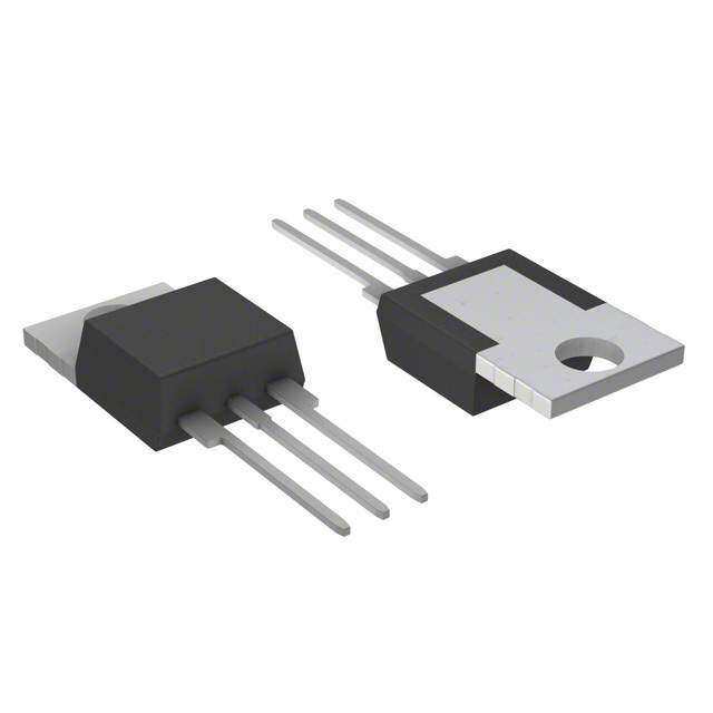
| 描述 | TRIAC SENS GATE 400V 4A TO220双向可控硅 400V 4A 10-10-10mA |
| 产品分类 | 双向可控硅分离式半导体 |
| GateTriggerCurrent-Igt | 10 mA, 25 mA |
| GateTriggerVoltage-Vgt | 2 V |
| 品牌 | Littelfuse |
| 产品手册 | |
| 产品图片 |
|
| rohs | 符合RoHS无铅 / 符合限制有害物质指令(RoHS)规范要求 |
| 产品系列 | 晶体闸流管,双向可控硅,Littelfuse Q4004L3- |
| 数据手册 | |
| 产品型号 | Q4004L3 |
| 三端双向可控硅类型 | 逻辑 - 灵敏栅极 |
| 不重复通态电流 | 46 A, 55 A |
| 产品目录页面 | |
| 产品种类 | 双向可控硅 |
| 供应商器件封装 | TO-220 隔离的标片 |
| 保持电流Ih最大值 | 20 mA |
| 关闭状态漏泄电流(在VDRMIDRM下) | 50 uA |
| 包装 | 散装 |
| 商标 | Littelfuse |
| 安装类型 | 通孔 |
| 安装风格 | Through Hole |
| 封装 | Bulk |
| 封装/外壳 | TO-220-3 隔离片 |
| 封装/箱体 | TO-220-3 |
| 工厂包装数量 | 500 |
| 开启状态RMS电流-ItRMS | 4 A |
| 开启状态电压 | 1.6 V |
| 最大工作温度 | + 125 C |
| 最小工作温度 | - 40 C |
| 栅极触发电压-Vgt | 2 V |
| 栅极触发电流-Igt | 10 mA, 25 mA |
| 标准包装 | 500 |
| 电压-断态 | 400V |
| 电压-栅极触发(Vgt)(最大值) | 1.3V |
| 电流-不重复浪涌50、60Hz(Itsm) | 46A,55A |
| 电流-保持(Ih)(最大值) | 20mA |
| 电流-栅极触发(Igt)(最大值) | 10mA |
| 电流-通态(It(RMS))(最大值) | 4A |
| 系列 | Q4004 |
| 配置 | 单一 |
| 额定重复关闭状态电压VDRM | 400 V |


- 商务部:美国ITC正式对集成电路等产品启动337调查
- 曝三星4nm工艺存在良率问题 高通将骁龙8 Gen1或转产台积电
- 太阳诱电将投资9.5亿元在常州建新厂生产MLCC 预计2023年完工
- 英特尔发布欧洲新工厂建设计划 深化IDM 2.0 战略
- 台积电先进制程称霸业界 有大客户加持明年业绩稳了
- 达到5530亿美元!SIA预计今年全球半导体销售额将创下新高
- 英特尔拟将自动驾驶子公司Mobileye上市 估值或超500亿美元
- 三星加码芯片和SET,合并消费电子和移动部门,撤换高东真等 CEO
- 三星电子宣布重大人事变动 还合并消费电子和移动部门
- 海关总署:前11个月进口集成电路产品价值2.52万亿元 增长14.8%


PDF Datasheet 数据手册内容提取
Thyristors 4 Amp Sensitive & Standard Triacs Lxx04xx & Qxx04xx Series RoHS Description This 4 Amp bidirectional solid state switch series is designed for AC switching and phase control applications such as motor speed and temperature modulation controls, lighting controls, and static switching relays. Sensitive type devices guarantee gate control in Quadrants I & IV as needed for digital control circuitry. Standard type devices normally operate in Quadrants I & III triggered from AC line. Features & Benefits • RoHS Compliant contact bounce that Agency Approval • Glass – passivated create voltage transients junctions • No contacts to wear out Agency Agency File Number from reaction of switching • Voltage capability up to events E71639 1000 V • Restricted (or limited) RFI - L Package only. • Surge capability up to generation, depending on - 400V and 600V for Sensitive Triac (L Device Type) 55 A - 400V, 600V, 800V, or 1000V for Standard Triac (Q Device Type) activation point of • The L-package has sine wave an isolation rating of • Requires only a short gate Main Features 2500V RMS activation pulse in each • Solid-state switching half-cycle Symbol Value Unit eliminates arcing or I 4 A T(RMS) Applications V /V 400, 600, 800 or 1000 V DRM RRM I 3 to 25 mA Typical applications are AC solid-state switches, power GT (Q1) tools, home/brown goods and white goods appliances. Sensitive gate Triacs can be directly driven by Schematic Symbol microprocessor or popular opto-couplers/isolators. Internally constructed isolated packages are offered for ease of heat sinking with highest isolation voltage. MT2 MT1 G Absolute Maximum Ratings — Sensitive Triacs (4 Quadrants) Symbol Parameter Value Unit I RMS on-state current Lxx04Ly TC = 90°C 4 A T(RMS) (full sine wave) Lxx04Ry/Lxx04Vy/Lxx04Dy T = 95°C C Non repetitive surge peak on-state current f = 50 Hz t = 20 ms 33 I A TSM (full cycle, TJ initial = 25°C) f = 60 Hz t = 16.7 ms 40 I2t I2t Value for fusing t = 8.3 ms 6.6 A2s p Critical rate of rise of on-state current di/dt f = 120 Hz T = 110°C 50 A/μs (I = 50mA with ≤ 0.1μs rise time) J G I Peak gate trigger current t=20μs T = 110°C 4 A GTM p J P Average gate power dissipation T = 110°C 0.3 W G(AV) J T Storage temperature range -40 to 150 °C stg T Operating junction temperature range -40 to 110 °C J Note: xx = voltage/10, y = sensitivity © 2019 Littelfuse, Inc. Specifications are subject to change without notice. Revised: 05/31/19
Thyristors 4 Amp Sensitive & Standard Triacs Absolute Maximum Ratings — Standard Triacs Symbol Parameter Value Unit I RMS on-state current Qxx04Ly TC = 105°C 4 A T(RMS) (full sine wave) Qxx04Ry/Qxx04Vy/Qxx04Dy T = 110°C C Non repetitive surge peak on-state current f = 50 Hz t = 20 ms 46 I A TSM (full cycle, TJ initial = 25°C) f = 60 Hz t = 16.7 ms 55 I2t I2t Value for fusing t = 8.3 ms 12.5 A2s p Critical rate of rise of on-state current di/dt f = 120 Hz T = 125°C 50 A/μs (I = 50mA with ≤ 0.1μs rise time) J G I Peak gate trigger current t=20μs T = 125°C 4 A GTM p J P Average gate power dissipation T = 125°C 0.3 W G(AV) J T Storage temperature range -40 to 150 °C stg T Operating junction temperature range -40 to 125 °C J Note: xx = voltage/10, y = sensitivity Electrical Characteristics (T = 25°C, unless otherwise specified) — Sensitive Triac (4 Quadrants) J Symbol Test Conditions Quadrant Lxx04x3 Lxx04x5 Lxx04x6 Lxx04x8 Unit I – II – III 3 5 5 10 I V = 12V R = 60 Ω MAX. mA GT D L IV 3 5 10 20 V V = 12V R = 60 Ω ALL MAX. 1.3 V GT D L V V = V R = 3.3 kΩ T = 110°C ALL MIN. 0.2 V GD D DRM L J I I = 100mA MAX. 5 10 10 15 mA H T 400V 25 25 30 35 dv/dt V = V Gate Open T = 100°C TYP. V/μs D DRM J 600V 15 15 20 25 (dv/dt)c (di/dt)c = 2.16 A/ms T = 110°C TYP. 0.5 1 1 1 V/μs J t I = 2 x I PW = 15μs I = 5.6 A(pk) TYP. 2.8 3.0 3.0 3.2 μs gt G GT T Electrical Characteristics (T = 25°C, unless otherwise specified) — Standard Triac J Symbol Test Conditions Quadrant Qxx04x3 Qxx04x4 Unit I – II – III MAX. 10 25 I V = 12V R = 60 Ω mA GT D L IV TYP. 25 50 V V = 12V R = 60 Ω I – II – III MAX. 1.3 1.3 V GT D L V V = V R = 3.3 kΩ T = 125°C ALL MIN. 0.2 0.2 V GD D DRM L J I I = 200mA MAX. 20 30 mA H T 400V 40 75 V = V Gate Open T = 125°C 600V 30 50 dv/dt D DRM J MIN. V/μs 800V 40 V = V Gate Open T = 100°C 1000V 50 D DRM J (dv/dt)c (di/dt)c = 2.16 A/ms T = 125°C TYP. 2 2 V/μs J t I = 2 x I PW = 15μs I = 5.6 A(pk) TYP. 2.5 3.0 μs gt G GT T dv/dt VD = 2/3 VDRM Gate Open T = 125°C 800V 40 V/μs J Note: xx = voltage/10, x = package © 2019 Littelfuse, Inc. Specifications are subject to change without notice. Revised: 05/31/19
Thyristors 4 Amp Sensitive & Standard Triacs Static Characteristics (T = 25°C, unless otherwise specified) J Symbol Test Conditions Value Unit V I = 5.6A t = 380 µs MAX. 1.60 V TM TM p T = 25°C 400-600V 5 μA Lxx04xy J T = 110°C 400-600V 200 μA I J DRM V = V MAX. T = 25°C 400-1000V 10 μA I DRM RRM J RRM Qxx04xy T = 125°C 400-800V 2 J mA T = 100°C 1000V 3 J Thermal Resistances Symbol Parameter Value Unit L/Qxx04Dy 1.5 L/Qxx04Ly 3.5 R Junction to case (AC) °C/W Ɵ(J-C) L/Qxx04Ry 2.2 L/Qxx04Vy 1.5 L/Qxx04Ly 50 R Junction to ambient L/Qxx04Ry 45 °C/W Ɵ(J-A) L/Qxx04Vy 70 Note: xx = voltage/10, x = package, y = sensitivity Figure 2: Normalized DC Gate Trigger Current for Figure 1: Definition of Quadrants All Quadrants vs. Junction Temperature ALL POLARITIES ARE REFERENCED TO MT1 4.0 MT2 POSITIVE (Positive Half Cycle) MT2 + MT2 (-)GIGATTE MT1 (+)IGGATTE MT1 IGT I(T = 25°C)GT J23..00 REF REF IGT - QQIIIII QQIIV + IGT o of MT2 MT2 ati 1.0 R (-)IGT (+)IGT GATE GATE 0.0 MT1 - MT1 -65 -40 -40 10 35 60 85 110 125 REF MT2 NEGATIVE REF Junction Temperature (TJ)- ºC (Negative Half Cycle) Additional Information Datasheet Resources Samples © 2019 Littelfuse, Inc. Specifications are subject to change without notice. Revised: 05/31/19
Thyristors 4 Amp Sensitive & Standard Triacs Figure 3: Normalized DC Holding Current Figure 4: Normalized DC Gate Trigger Voltage for vs. Junction Temperature All Quadrants vs. Junction Temperature 4.0 2.0 IH I(T = 25°C)H J 23..00 VGT V(T = 25°C)GT J 11..05 Ratio of 1.0 Ratio of 0.5 0.0 0.0 -65 -40 -40 10 35 60 85 110 125 -65 -40 -40 10 35 60 85 110 125 Junction Temperature (T)- ºC Junction Temperature (T)- ºC J J Figure 5: Power Dissipation (Typical) Figure 6: Maximum Allowable Case Temperature vs. RMS On-State Current vs. On-State Current 4.0 125 Qxx04Ry CURRENT WAVE FORM: Sinusoidal 120 Qxx04Vy LOAD: Resistive or Inductive Average On-State wer Dissipation (P) - WattsD(AV)321...000 CLCOUOARNDRD:E URNCeTTs WiIsOtANivV eAE oN FrGO InLRdEMu: 3:c 6Sti0ivn°eusoidal Maximum Allowable Case Temperature (T) - °CC1111099011050505 QxxQ04xLxy04Dy CCasOA sSNhEDo TUwECnMT oPIOnE NRDA iAmTNUeGnRLsEEi:o :M n3a6el0a D°surarwedin g o 85 P 80 0.0 75 0.0 1.0 2.0 3.0 4.0 5.0 0 1 2 3 4 5 6 RMS On-State Current (IT(RMS)) - Amps RMS On-State Current (IT(RMS)) - Amps Figure 7: Maximum Allowable Case Temperature Figure 8: Maximum Allowable Ambient Temperature vs. On-State Current vs. On-State Current 110 120 Lxx04Ry CURRENT WAVE FORM: Sinusoidal 105 Lxx04Vy LOAD: Resistive or Inductive CURRENT WAVEFORM: Sinusoidal m Allowable erature (T) - °CC108995050 Lxx04Ly Lxx04Dy CCasOA sSNhEDo TUwECnMT oPIOnE NRDA iAmTNUeGnRLsEEi:o :M n3a6el0a D°surarwedin g um Allowable mperature (T) - °CA10800 LCFOROEANEDD A:U RIRCe TsRiIsAOtTNivIQQN eAxx GNoxx r00G– 4I4 LnNRLEdyOy:u 3cH6tEi0vA°e T SINK MaximuCase Temp 778050 MaximAmbient Te 6400 L/Qxx04Vy Lxx04Ly 65 60 20 0 1 2 3 4 5 6 0.0 0.2 0.4 0.6 0.8 1.0 1.2 1.4 1.6 1.8 2.0 Note: xx = voltage/10, y = sensitivity RMS On-State Current (IT(RMS)) - Amps RMS On-State Current [IT(RMS)] - Amps © 2019 Littelfuse, Inc. Specifications are subject to change without notice. Revised: 05/31/19
Thyristors 4 Amp Sensitive & Standard Triacs Figure 9: On-State Current vs. On-State Voltage (Typical) 20 T = 25°C 18 J us mps 16 or InstantaneoCurrent (I) - AT1114208 Positive On-State 64 2 0 0.6 0.8 1.0 1.2 1.4 1.6 1.8 Positive or Instantaneous On-State Voltage (V) - Volts T Figure 10: Surge Peak On-State Current vs. Number of Cycles 100 nt urre QQxxxx0044RLyy SLouapdp:l yR Ferseisqtuiveency: 60Hz Sinusoidal C Qxx04Dy State Qxx04Vy SRpMeSc ifiOcn C-Satsaete T [eITm(RMpSe)]r:a Mtuarex Rated Value at n- n-repetitive) O) – Amps(ITSM10 LLLLxxxxxxxx00004444DVRLyyyy N12..o Gf Ottoeeavlmslteo:eprw lecoiornaandgtt umrsrouealr ymgh eana soyc t urb erberteeu l nrornets eptind edt aetuotrrev insdatg le.u aanndtidyl - jsiumtnamctetei o dnia tely o N rated value. e ( g ur S k a e P 1 1 10 100 1000 Surge Current Duration – Full Cycles Note: xx = voltage/10, y = sensitivity © 2019 Littelfuse, Inc. Specifications are subject to change without notice. Revised: 05/31/19
Thyristors 4 Amp Sensitive & Standard Triacs Soldering Parameters Reflow Condition Pb – Free assembly t P T P - Temperature Min (Ts(min)) 150°C e RRaammpp--uupp Pre Heat -- TTeimmep e(mraitnu rteo Mmaaxx )( T(tss(m)ax)) 2600 0–° C180 secs rutarep TS(mTaxL) tL m RRaammpp--ddoown Average ramp up rate (Liquidus Temp) (T) to PPrreehheeaatt peak L 5°C/second max eT T S(min) t T to T - Ramp-up Rate 5°C/second max S S(max) L - Temperature (T) (Liquidus) 217°C Reflow L 25 - Temperature (t) 60 – 150 seconds time to peak temperature L Time Peak Temperature (T) 260°C +0/-5 P Time within 5°C of actual peak Temperature 20 – 40 seconds (t) p Ramp-down Rate 5°C/second max Time 25°C to peak Temperature (T) 8 minutes Max. P Do not exceed 280°C Physical Specifications Environmental Specifications Test Specifications and Conditions Terminal Finish 100% Matte Tin-plated MIL-STD-750, M-1040, Cond A Applied Peak AC Blocking AC voltage @ 125°C for 1008 hours Body Material UL Recognized compound meeting flammability MIL-STD-750, M-1051, rating V-0 Temperature Cycling 100 cycles; -40°C to +150°C; 15-min dwell time Terminal Material Copper Alloy EIA / JEDEC, JESD22-A101 Temperature/Humidity 1008 hours; 320V - DC: 85°C; 85% rel humidity MIL-STD-750, M-1031, High Temp Storage 1008 hours; 150°C Design Considerations Low-Temp Storage 1008 hours; -40°C Careful selection of the correct component for the application’s operating parameters and environment will Resistance to MIL-STD-750 Method 2031 Solder Heat go a long way toward extending the operating life of the Thyristor. Good design practice should limit the maximum Solderability ANSI/J-STD-002, category 3, Test A continuous current through the main terminals to 75% of Lead Bend MIL-STD-750, M-2036 Cond E the component rating. Other ways to ensure long life for a power discrete semiconductor are proper heat sinking and selection of voltage ratings for worst case conditions. Overheating, overvoltage (including dv/dt), and surge currents are the main killers of semiconductors. Correct mounting, soldering, and forming of the leads also help protect against component damage. © 2019 Littelfuse, Inc. Specifications are subject to change without notice. Revised: 05/31/19
Thyristors 4 Amp Sensitive & Standard Triacs Dimensions — TO-220AB (R-Package) — Non-Isolated Mounting Tab Common with Center Lead TC MEASURING POINT AREA (REF.) 0.17 IN2 Inches Millimeters O Dimension E A P .83.2130 Min Max Min Max MT2 A 0.380 0.420 9.65 10.67 B C B 0.105 0.115 2.67 2.92 13.36 D .526 C 0.230 0.250 5.84 6.35 7.01 D 0.590 0.620 14.99 15.75 .276 E 0.142 0.147 3.61 3.73 F 0.110 0.130 2.79 3.30 F NOTCH IN GATE LEAD G 0.540 0.575 13.72 14.61 TO ID. R NTAOBN-ISOLATED H 0.025 0.035 0.64 0.89 G L J 0.195 0.205 4.95 5.21 H K 0.095 0.105 2.41 2.67 L 0.060 0.075 1.52 1.91 K N M 0.085 0.095 2.16 2.41 J M Note: Maximum torque to MT1 MT2GATE be applied to mounting tab N 0.018 0.024 0.46 0.61 is 8 in-lbs. (0.904 Nm). O 0.178 0.188 4.52 4.78 P 0.045 0.060 1.14 1.52 R 0.038 0.048 0.97 1.22 Dimensions — TO-220AB (L-Package) — Isolated Mounting Tab T MEASURING POINT AREA (REF.) 0.17 IN2 C Inches Millimeters O Dimension E A P .83.2130 Min Max Min Max A 0.380 0.420 9.65 10.67 B C B 0.105 0.115 2.67 2.92 13.36 D .526 C 0.230 0.250 5.84 6.35 7.01 D 0.590 0.620 14.99 15.75 .276 E 0.142 0.147 3.61 3.73 F 0.110 0.130 2.79 3.30 F G 0.540 0.575 13.72 14.61 R H 0.025 0.035 0.64 0.89 G L J 0.195 0.205 4.95 5.21 H K 0.095 0.105 2.41 2.67 Note: Maximum torque to be applied to mounting tab L 0.060 0.075 1.52 1.91 K N is 8 in-lbs. (0.904 Nm). M 0.085 0.095 2.16 2.41 J M MT1 MT2GATE N 0.018 0.024 0.46 0.61 O 0.178 0.188 4.52 4.78 P 0.045 0.060 1.14 1.52 R 0.038 0.048 0.97 1.22 © 2019 Littelfuse, Inc. Specifications are subject to change without notice. Revised: 05/31/19
Thyristors 4 Amp Sensitive & Standard Triacs Dimensions — TO-251AA (V-Package) — V-PAK Through Hole TC MEASURING POINT AREA: 0.040 IN2 Inches Millimeters Dim MT2 E H 5.28 Min Typ Max Min Typ Max D J .208 A 0.037 0.040 0.043 0.94 1.01 1.09 A B 0.235 0.242 0.245 5.97 6.15 6.22 5.34 .210 C 0.350 0.361 0.375 8.89 9.18 9.53 B D 0.205 0.208 0.213 5.21 5.29 5.41 P R S E 0.255 0.262 0.265 6.48 6.66 6.73 Q K F 0.027 0.031 0.033 0.69 0.80 0.84 C G 0.087 0.090 0.093 2.21 2.28 2.36 H 0.085 0.092 0.095 2.16 2.34 2.41 I 0.176 0.180 0.184 4.47 4.57 4.67 MMTT21 G F L J 0.018 0.020 0.023 0.46 0.51 0.58 GATE I K 0.035 0.037 0.039 0.90 0.95 1.00 L 0.018 0.020 0.023 0.46 0.52 0.58 P 0.042 0.047 0.052 1.06 1.20 1.32 Q 0.034 0.039 0.044 0.86 1.00 1.11 R 0.034 0.039 0.044 0.86 1.00 1.11 S 0.074 0.079 0.084 1.86 2.00 2.11 Dimensions — TO-252AA (D-Package) — D-PAK Surface Mount MT2 DE TC MEASURING POINT .52.0288 .62.6741 Dim Inches Millimeters Min Typ Max Min Typ Max A 5.34 6.71 A 0.037 0.040 0.043 0.94 1.01 1.09 .210 .264 B B 0.235 0.243 0.245 5.97 6.16 6.22 C 0.106 0.108 0.113 2.69 2.74 2.87 1.60 P .063 C Q D 0.205 0.208 0.213 5.21 5.29 5.41 1.80 GATE .071 E 0.255 0.262 0.265 6.48 6.65 6.73 MT1 F AREA: 0.040 IN2 MT2 G .1138 .41.8610 F 0.027 0.031 0.033 0.69 0.80 0.84 I G 0.087 0.090 0.093 2.21 2.28 2.36 O L H 0.085 0.092 0.095 2.16 2.33 2.41 K J H I 0.176 0.179 0.184 4.47 4.55 4.67 M J 0.018 0.020 0.023 0.46 0.51 0.58 N K 0.035 0.037 0.039 0.90 0.95 1.00 L 0.018 0.020 0.023 0.46 0.51 0.58 M 0.000 0.000 0.004 0.00 0.00 0.10 N 0.021 0.026 0.027 0.53 0.67 0.69 O 0° 0° 5° 0° 0° 5° P 0.042 0.047 0.052 1.06 1.20 1.32 Q 0.034 0.039 0.044 0.86 1.00 1.11 © 2019 Littelfuse, Inc. Specifications are subject to change without notice. Revised: 05/31/19
Thyristors 4 Amp Sensitive & Standard Triacs Product Selector Voltage Gate Sensitivity Quadrants Part Number Type Package 400V 600V 800V 1000V I – II – III IV Lxx04L3 X X 3 mA 3 mA Sensitive Triac TO-220L Lxx04D3 X X 3 mA 3 mA Sensitive Triac TO-252 D-PAK Lxx04R3 X X 3mA 3mA Sensitive Triac TO-220R Lxx04V3 X X 3 mA 3 mA Sensitive Triac TO-251 V-PAK Lxx04L5 X X 5 mA 5 mA Sensitive Triac TO-220L Lxx04D5 X X 5 mA 5 mA Sensitive Triac TO-252 D-PAK Lxx04R5 X X 5mA 5mA Sensitive Triac TO-220R Lxx04V5 X X 5 mA 5 mA Sensitive Triac TO-251 V-PAK Lxx04L6 X X 5 mA 10 mA Sensitive Triac TO-220L Lxx04D6 X X 5 mA 10 mA Sensitive Triac TO-252 D-PAK Lxx04R6 X X 5mA 10mA Sensitive Triac TO-220R Lxx04V6 X X 5 mA 10 mA Sensitive Triac TO-251 V-PAK Lxx04L8 X X 10 mA 20 mA Sensitive Triac TO-220L Lxx04D8 X X 10 mA 20 mA Sensitive Triac TO-252 D-PAK Lxx04R8 X X 10mA 20mA Sensitive Triac TO-220R Lxx04V8 X X 10 mA 20 mA Sensitive Triac TO-251 V-PAK Qxx04L3 X X X 10 mA Standard Triac TO-220L Qxx04D3 X X X 10 mA Standard Triac TO-252 D-PAK Qxx04V3 X X X 10 mA Standard Triac TO-251 V-PAK Qxx04R3 X X X 10mA Standard Triac TO-220R Qxx04L4 X X X X 25 mA Standard Triac TO-220L Qxx04D4 X X X X 25 mA Standard Triac TO-252 D-PAK Qxx04R4 X X X X 25mA Standard Triac TO-220R Qxx04V4 X X X X 25 mA Standard Triac TO-251 V-PAK Packing Options Part Number Marking Weight Packing Mode Base Quantity L/Qxx04LyTP L/Qxx04Ly 2.2 g Tube 500 (50 per tube) L/Qxx04DyRP L/Qxx04Dy 0.3 g Embossed Carrier 2500 L/Qxx04DyTP L/Qxx04Dy 0.3 g Tube Pack 750 (75 per tube) L/Qxx04VyTP L/Qxx04Vy 0.4 g Tube Pack 750 (75 per tube) L/Qxx04LyTP L/Qxx04Ly 2.2g Tube 500 (50 per tube) Note: xx = Voltage/10; y = Sensitivity © 2019 Littelfuse, Inc. Specifications are subject to change without notice. Revised: 05/31/19
Thyristors 4 Amp Sensitive & Standard Triacs TO-252 Embossed Carrier Reel Pack (RP) Specifications Meets all EIA-481-2 Standards 0.157 (4.0) 0.059 DIA Gate (1.5) MT1 (01.66.30) (01.532.34)* XXXXXX XXDC XXXXXX XXDC XXXXXX XXDC XXXXXX *Cover tape 0.315 MT2 (8.0) 12.99 0.512 (13.0) Arbor (330.0) Dimensions Hole Dia. are in inches (and millimeters). 0.64 (16.3) Direction of Feed Part Numbering System Part Marking System Q6004L4xx TO-251AA- (V Package) TO-252AA- (D Package) DEVICE TYPE LEAD FORM DIMENSIONS L : Sensitive Triac xx : Lead Form Option Q : Standard Triac L6004V4 L6004V4 SENSITIVITY & TYPE Sensitive Triac: VOLTAGE RATING 3 : 3 mA (QI, II, III, IV) 4600 :: 460000VV 56 :: 55 mmAA ((QQII,, IIII,, IIIIII,) IV) YMLDD ® YMLDD ® 80 : 800V 10 mA (QIV) K0 : 1000V 8 : 10 mA (QI, II, III) Date Code Marking 20 mA (QIV) Y:Year Code Standard Triac: M: Month Code 3 : 10 mA (QI, II, III) L: Location Code 4 : 25 mA (QI, II, III) DD: Calendar Code CURRENT RATING PACKAGE TYPE 04 : 4A L : TO-220 Isolated TO-220 AB - (L and R Package) R : TO-220 Non-Isolated V : TO-251 (V-Pak) D : TO-252 (D-Pak) Q6004R4 YM ® ® Date Code Marking Y:Year Code M: Month Code XXX: Lot Trace Code © 2019 Littelfuse, Inc. Specifications are subject to change without notice. Revised: 05/31/19 ®