
 Datasheet下载
- 型号: PX2AF1XX100PSBDX
- 制造商: Honeywell Solid State Electronics
- 库位|库存: xxxx|xxxx
- 要求:
| 数量阶梯 | 香港交货 | 国内含税 |
| +xxxx | $xxxx | ¥xxxx |
查看当月历史价格
查看今年历史价格
PX2AF1XX100PSBDX产品简介:
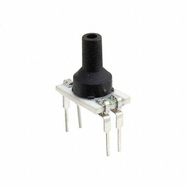
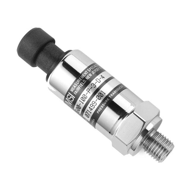
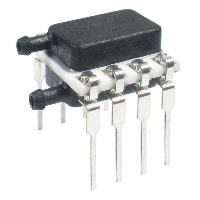
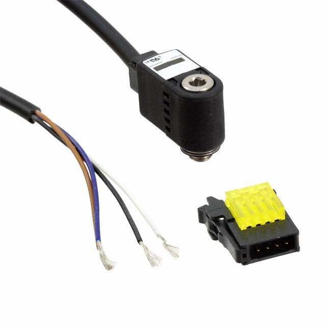
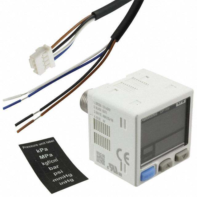
ICGOO电子元器件商城为您提供PX2AF1XX100PSBDX由Honeywell Solid State Electronics设计生产,在icgoo商城现货销售,并且可以通过原厂、代理商等渠道进行代购。 PX2AF1XX100PSBDX价格参考。Honeywell Solid State ElectronicsPX2AF1XX100PSBDX封装/规格:压力传感器,变送器, 密封压力计 压力 传感器 100 PSI(689.48 kPa) 母头 - 7/16"(11.11mm)UNF Schrader 0.25 V ~ 10.25 V 圆柱型。您可以下载PX2AF1XX100PSBDX参考资料、Datasheet数据手册功能说明书,资料中有PX2AF1XX100PSBDX 详细功能的应用电路图电压和使用方法及教程。
Honeywell Sensing and Productivity Solutions的PX2AF1XX100PSBDX是一款压力传感器,广泛应用于各种工业和商业场景中。这款型号属于PX2A系列,设计用于测量气体或液体的表压,具有出色的精度、稳定性和可靠性。以下是该型号的一些典型应用场景:

 1. 工业自动化与控制
   PX2AF1XX100PSBDX常用于工业自动化系统中,如工厂的生产线监控、流体控制系统等。它可以实时监测管道内的压力变化,确保设备在安全范围内运行,避免因压力过高或过低导致的设备损坏或生产中断。

 2. HVAC系统
   在暖通空调(HVAC)系统中,该传感器可以用于监测空气或制冷剂的压力,确保系统的高效运行。通过精确的压力反馈,控制器可以根据实际需求调整风机、压缩机等设备的工作状态,从而提高能源利用效率,降低能耗。

 3. 医疗设备
   该型号的压力传感器也适用于医疗设备,如呼吸机、麻醉机等。它能够精确测量气道压力,确保患者在治疗过程中获得适当的气流支持,保障患者的安全和舒适度。

 4. 水处理与泵系统
   在水处理厂或泵站中,PX2AF1XX100PSBDX可用于监测水泵入口和出口的压力,确保水流顺畅且系统处于最佳工作状态。通过实时压力监测,可以及时发现管道堵塞或其他异常情况,防止设备故障。

 5. 油气行业
   在石油和天然气行业中,该传感器可用于井口压力监测、管道输送系统中的压力控制等。它能够承受恶劣的工作环境,并提供高精度的压力数据,帮助操作人员进行远程监控和故障诊断。

 6. 实验室与科研
   该型号的压力传感器也广泛应用于实验室环境中,用于实验装置中的压力测量。它的高精度和稳定性使其成为科研人员的理想选择,尤其是在需要精确控制实验条件的情况下。

总之,PX2AF1XX100PSBDX凭借其优异的性能和广泛的适用性,在多个领域中发挥着重要作用,能够满足不同应用场景下的压力测量需求。
| 参数 | 数值 |
| 产品目录 | |
| 描述 | PRESSURE TRANSDUCER PSIS |
| 产品分类 | |
| 品牌 | Honeywell Sensing and Control |
| 数据手册 | http://sensing.honeywell.com/index.php?ci_id=142976http://sensing.honeywell.com/index.php?ci_id=54928http://sensing.honeywell.com/index.php?ci_id=145416 |
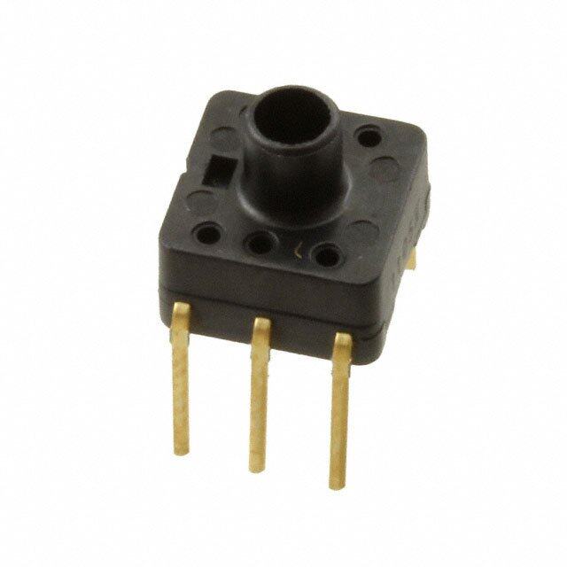
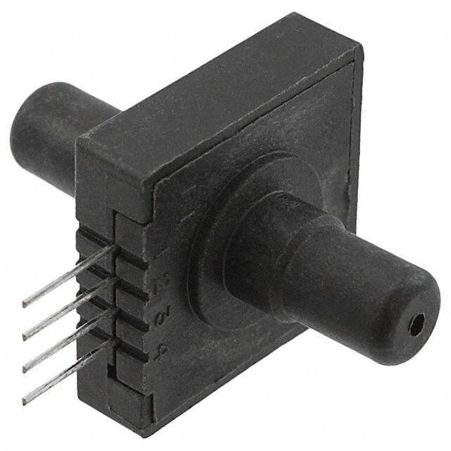
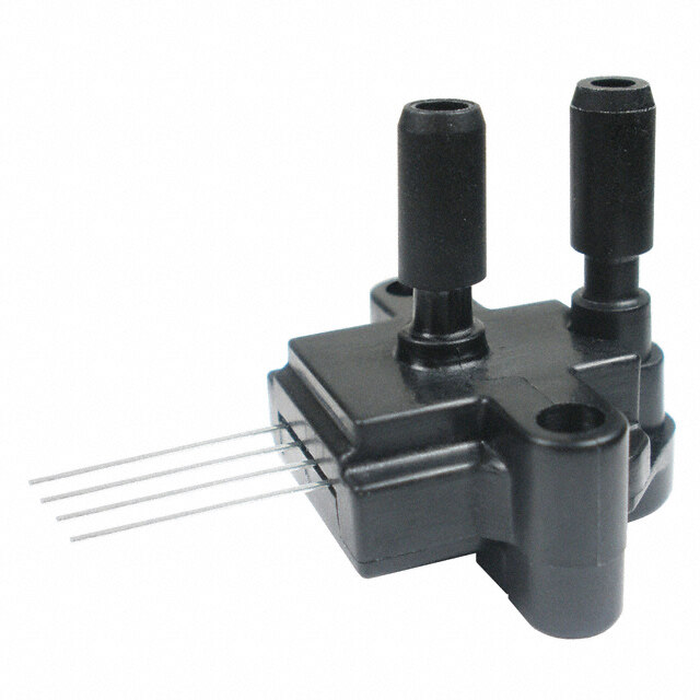
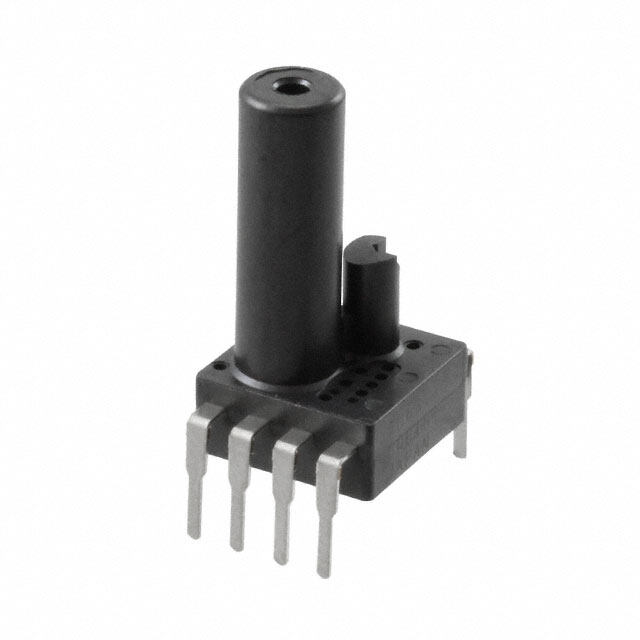
| 产品图片 |
|
| 产品型号 | PX2AF1XX100PSBDX |
| rohs | 无铅 / 符合限制有害物质指令(RoHS)规范要求 |
| 产品系列 | PX2 |
| 产品培训模块 | http://www.digikey.cn/PTM/IndividualPTM.page?site=cn&lang=zhs&ptm=25858 |
| 出厂设置 | - |
| 压力类型 | 密封压力计 |
| 封装/外壳 | 圆柱型 |
| 工作压力 | 100 PSI |
| 工作温度 | -40°C ~ 125°C |
| 标准包装 | 40 |
| 电压-电源 | 13 V ~ 30 V |
| 端口尺寸 | 孔式,1/4",0.45"(6.35mm)孔式闪光气门嘴 |
| 端子类型 | |
| 精度 | ±0.25%FSS |
| 输出 | 0.25 V ~ 10.25V |


- 商务部:美国ITC正式对集成电路等产品启动337调查
- 曝三星4nm工艺存在良率问题 高通将骁龙8 Gen1或转产台积电
- 太阳诱电将投资9.5亿元在常州建新厂生产MLCC 预计2023年完工
- 英特尔发布欧洲新工厂建设计划 深化IDM 2.0 战略
- 台积电先进制程称霸业界 有大客户加持明年业绩稳了
- 达到5530亿美元!SIA预计今年全球半导体销售额将创下新高
- 英特尔拟将自动驾驶子公司Mobileye上市 估值或超500亿美元
- 三星加码芯片和SET,合并消费电子和移动部门,撤换高东真等 CEO
- 三星电子宣布重大人事变动 还合并消费电子和移动部门
- 海关总署:前11个月进口集成电路产品价值2.52万亿元 增长14.8%
PDF Datasheet 数据手册内容提取
Heavy Duty Pressure Transducers 50069942 Datasheet PX2 Series, 1 bar to 70 bar | 100 kPa to 7 MPa | 15 psi to 1000 psi Issue I Datasheet FEATURES • Pressure range: 1 bar to 70 bar | 100 kPa to 7 MPa | 15 psi to 1000 psi • Pressure reference: Absolute, sealed gage or vented gage • Pressure port types: 7/16-20 UNF 1/4 in 45° Flare Female Schrader (SAE J512), 7/16-20 UNF 45° Flare Male (SAE J513), 7/16-20 UNF 37° Flare Male (SAE J514), G1/4 (ISO 1179-3), G1/8 (ISO 1179-3), M12 x 1.5 (ISO 6149-3), 1/4-18 NPT, 1/8-27 NPT, 9/16-18 UNF, (SAE J1926-3), or 7/16-20 UNF (SAE J1926-3) • Electrical connector types: Metri-Pack 150 (UL 94 HB or V-0 options), Micro M12, DIN, Deutsch, or cable harness (1 m, 2 m, 3 m, or 5 m) DESCRIPTION • Total Error Band: ±2.0 % Honeywell’s PX2 Series Heavy Duty Pressure Transducers • Operating and compensated temperature range: -40°C to are a portfolio of configurable pressure sensors that use 125°C [-40°F to 257°F] piezoresistive sensing technology with ASIC (Application • Response time: <2 ms Specific Integrated Circuit) signal conditioning in a stainless • Life: Minimum of 10 million cycles to operating pressure steel housing. The PX2 Series is fully calibrated and • Output transfer function: Ratiometric, regulated or current compensated for offset, sensitivity, temperature effects and • Mechanical shock rating: 100 G per MIL-STD-202F, Method non-linearity using the on-board ASIC. These transducers 213B, Cond. F measure absolute, sealed gage, or vented gage pressure. The • Vibration rating: 20 G sweep, 10 Hz to 2000 Hz absolute versions have an internal vacuum reference and • Ingress protection: Up to IP69K an output value proportional to absolute pressure, sealed • Radiated immunity protection: Up to 100 V/m (ISO 11452-2) gage versions have an internal pressure reference of one • Flame retardant options: UL 94 HB standard on all electrical atmosphere at sea level, and vented gage versions measure terminations; UL 94 V-0 available upon request pressure with respect to ambient pressure. They are RoHS compliant and are designed and manufactured according to POTENTIAL APPLICATIONS ISO 9001 standards. • Industrial: Refrigerant pressure monitoring in HVAC/R systems; air compressor system pressure VALUE TO CUSTOMERS • Transportation: Air system monitoring; hydraulic oil pressure • Media compatibility: Common HFC (hydrofluorocarbon) monitoring refrigerants such as R410A and R134A, next generation low global warming potential (GWP) refrigerants such as R448A The PX2 Series is not recommended for use with media (Solstice® N40), R32 and R1234ZE, engine oil, petroleum- involving water, saturated air such as steam and vapor, and based hydraulic fluids, DOT 3 brake fluid, and dry air. For ammonia. ammonia and other corrosive media, see Honeywell’s SPT Series. PORTFOLIO • Enhanced durability: The PX2 Series can operate in the Honeywell’s PX2 Series joins the PX3 Series, MLH Series, and rigorous environments commonly found in HVAC/R and air SPT Series heavy duty pressure transducers. compressor applications. The sensor can survive at least 10 million pressure cycles and has an ingress protection rating up to IP69K. Sensing and Internet of Things
Heavy Duty Pressure Transducers PX2 Series, 1 bar to 70 bar | 100 kPa to 7 MPa | 15 psi to 1000 psi Table 1. Performance Specifications1 Characteristic Parameter Operating temperature range2 -40°C to 125°C [-40°F to 257°F] Storage temperature range3 -40°C to 125°C [-40°F to 257°F] Compensated temperature range4 -40°C to 125°C [-40°F to 257°F] Overpressure minimum rating5 (See Table 3.) Burst pressure minimum rating6 (See Table 3.) Long term stability ±0.5 %FSS9 (1000 hr at 25°C [77°F]) Accuracy7 ±0.25 %FSS9 (See Figure 1.) Offset error8 ±1 %FSS9 Total Error Band10 ±2 %FSS9 (-40°C to 125°C [-40°F to 257°F]) (See Figure 1.) Response time11 <2 ms Turn on time12 <7 ms Life13 minimum of 10 million cycles to operating pressure 1 All specifications apply at 25°C and under operating conditions unless otherwise noted. 2 Operating Temperature Range: The temperature range over which the product will produce an output proportional to pressure but may not remain within the specified performance limits. 3 Storage Temperature Range: The temperature range over which the product may safely be exposed without excitation or pressure applied. Under these conditions the product will remain in specification after excursion to any temperatures within this range. Exposure to temperatures outside this range may cause permanent damage to the product. 4 Compensated Temperature Range: The temperature range (or ranges) over which the product will produce an output proportional to pressure within the specified performance limits. 5 Overpressure: The absolute maximum rating for pressure which may be safely applied to the product for it to remain in specification once pressure is returned to the operating pressure range. Exposure to higher pressure may cause permanent damage to the product. 6 Burst Pressure: The maximum pressure that may be applied to the product without causing escape of the pressure media. The product should not be expected to function after exposure to any pressure beyond the rated burst pressure. This rating is also the case burst rating of the product. 7 Accuracy: The maximum deviation in output from a Best Fit Straight Line (BFSL) fitted to the output measured over the pressure range at 25°C. Includes all errors due to pressure non-linearity, pressure hysteresis, and non-repeatability. 8 Offset Error: the maximum deviation in the output signal obtained when the reference pressure is applied at 25°C relative to the ideal transfer function. 9 Full Scale Span (FSS): The algebraic difference between the output signal measured at the maximum (Pmax.) and minimum (Pmin.) limits of the pressure range. 10 Total Error Band: The maximum deviation from the ideal transfer function over the entire compensated temperature and pressure range. Includes all errors due to offset, full scale span, pressure non-linearity, pressure hysteresis, repeatability, thermal effect on offset, thermal effect on span, and thermal hysteresis. 11 Response Time: The response time of the transducer is the maximum amount of time that the transducer will take for the transducer to output a change from 10% to 90% of full scale in response to a 0% to 100% full scale step input pressure range. 12 Turn On Time: Duration from power applied until first valid output. 13 Life may vary depending on the application in which transducer is used. Figure 1. Total Error Band (TEB) for the Total Error Band Series All Possible Errors Offset Full Scale Span Pressure Non-Linearity Accuracy Total Pressure Hysteresis BFSL Error Pressure Non-Repeatability Band Thermal Effect on Offset Thermal Effect on Span Thermal Hysteresis 2 Sensing and Internet of Things
Heavy Duty Pressure Transducers PX2 Series, 1 bar to 70 bar | 100 kPa to 7 MPa | 15 psi to 1000 psi Table 2. Electrical Specifications Current Ratiometric Output Regulated Output Output Characteristic Output Transfer Function Order Code1 AA AB AC AD CH BC BD BE BG Output transfer function1: null output value 10% of Vs 5% of Vs 10% of Vs 5% of Vs 4 mA 1 V 0.25 V 0.5 V 1 V full scale output value 90% of Vs 95% of Vs 90% of Vs 95% of Vs 4 mA 6 V 10.25 V 4.5 V 5 V full scale span (FSS) 80% of Vs 90% of Vs 80% of Vs 90% of Vs 16 mA 5 V 10 V 4 V 4 V operating supply voltage, min.(Vs)2 4.75 V 4.5 V 3.135 V 3.135 V 8 V 9 V 13 V 8 V 8 V operating supply voltage, typ. (Vs)2 5 V 5 V 3.3 V 3.3 V — — — — — operating supply voltage, max. (Vs)2 5.25 V 5.5 V 3.465 V 3.465 V 30 V4 30 V3 30 V3 30 V3 30 V3 Supply current (typ.) 5 mA 4 mA — 5.5 mA Output load (pull up or down): minimum 2 kOhm — 2 kOhm maximum — (Vs - 8) x — 50 Ohm4 Absolute voltage ratings5: minimum6 -16 V -16 V -16 V maximum6 16 V 30 V 30 V maximum applied to output pin Vs — 12 V (short circuit protection)7 EMC rating8: CE compliance: electrostatic discharge ±4 kV contact, ±8 kV air per IEC 61000-4-2 radiated immunity 10 V/m (80 MHz to 1000 MHz) per IEC 61000-4-3 fast transient burst ±1 kV per IEC61000-4-4 immunity to conducted disturbances 3 V per IEC61000-4-6 radiated emissions 40 dB 30 MHz to 230 MHz; 47 dB 230 MHz to 1000 MHz per CISPR 11 ISO 11452-2 radiated immunity 100 V/m 200 MHz to 2 GHz 20 V/m 200 MHz to 2 GHz 1 Output transfer function options are shown in the Nomenclature and Order Guide. (See Figure 4.) 2 Transducer will not produce valid output when supply voltage is outside of operating range. 3 Applies at 25°C. See Figure 2 for Regulated Output Supply Voltage. 4 Applies at 25°C. See Figure 3 for Current Output Supply Voltage. 5 Absolute maximum ratings are the extreme limits the device can withstand without damage to the product. Voltages above these ratings may cause permanent damage. Exposure to absolute maximum conditions for extended periods may degrade device reliability. 6 Absolute voltage applies to potential across power and ground terminals. 7 Short circuit protection between output pin and ground, and output pin and supply pin. 8 All EMC ratings verified with the Metri-Pack 150 electrical connector type. Figure 2. Regulated Output Supply Voltage Figure 3. Current Output Supply Voltage Sensing and Internet of Things 3
Heavy Duty Pressure Transducers PX2 Series, 1 bar to 70 bar | 100 kPa to 7 MPa | 15 psi to 1000 psi Table 3. Pressure Ratings bar kPa MPa psi Operating Over- Burst Operating Over- Burst Operating Over- Burst Operating Over- Burst Pressure pressure Pressure Pressure pressure Pressure Pressure pressure Pressure Pressure pressure Pressure 1 5 8 100 500 800 1 3.1 5.1 15 70 115 1.6 5 8 160 1000 1700 1.6 5.2 8.6 30 150 250 2 10 17 250 1000 1700 2.5 6.9 10.3 50 250 400 2.5 10 17 400 1700 2700 4 6.9 10.3 100 450 750 4 17 27 600 3100 5100 4.6 6.9 10.3 150 450 750 6 31 51 — — — 6 13.8 20.6 200 750 1250 8 31 51 — — — 7 13.8 20.6 250 750 1250 10 31 51 — — — — — — 300 1000 1500 16 52 86 — — — — — — 500 1000 1500 25 69 103 — — — — — — 600 1000 1500 34 69 103 — — — — — — 667 1000 1500 40 69 103 — — — — — — 750 1500 2250 46 69 103 — — — — — — 800 1500 2250 60 138 206 — — — — — — 850 2000 3000 70 138 206 — — — — — — 1000 2000 3000 Table 4. Pressure Reference Types Pressure Reference Description Output is proportional to the difference between applied pressure and a built-in fixed reference to Absolute vacuum (zero pressure), where the minimum operating pressure is set to absolute zero pressure (perfect vacuum). Output is proportional to the difference between applied pressure and a built-in fixed reference to Sealed gage1 1 atmA, where the minimum operating pressure is set to 14.7 psiA (1 atmA). Sensor measures pressure relative to ambient pressure. Output is proportional to the difference Vented gage2 between applied pressure and atmospheric (ambient) pressure, where the minimum operating pressure is set to atmospheric pressure. 1 Sealed gage option only available in pressure ranges at or above 100 psi. 2 Vented gage option only available in pressure ranges between 100 psi and 667 psi. 4 Sensing and Internet of Things
Heavy Duty Pressure Transducers PX2 Series, 1 bar to 70 bar | 100 kPa to 7 MPa | 15 psi to 1000 psi Table 3. Pressure Ratings Table 5. Environmental and Mechanical Characteristics bar kPa MPa psi Characteristic Parameter Operating Over- Burst Operating Over- Burst Operating Over- Burst Operating Over- Burst Mechanical shock 100 G per MIL-STD-202F, Method 213B, Cond. F (at 25°C) Pressure pressure Pressure Pressure pressure Pressure Pressure pressure Pressure Pressure pressure Pressure Vibration 20 G sweep, 10 Hz to 2000 Hz (at 25°C) 1 5 8 100 500 800 1 3.1 5.1 15 70 115 Enclosure rating per electrical connector type selection (See Figure 5.) 1.6 5 8 160 1000 1700 1.6 5.2 8.6 30 150 250 Wetted materials: port 304 stainless steel 2 10 17 250 1000 1700 2.5 6.9 10.3 50 250 400 substrate alumina ceramic 2.5 10 17 400 1700 2700 4 6.9 10.3 100 450 750 adhesives epoxy 4 17 27 600 3100 5100 4.6 6.9 10.3 150 450 750 electronics glass, silicon 6 31 51 — — — 6 13.8 20.6 200 750 1250 External materials: 8 31 51 — — — 7 13.8 20.6 250 750 1250 housing 304 stainless steel connector: 10 31 51 — — — — — — 300 1000 1500 UL 94 HB (standard) PBT 30% GF, black 16 52 86 — — — — — — 500 1000 1500 UL 94 V-0 (optional) PBT 30% GF, natural (beige) 25 69 103 — — — — — — 600 1000 1500 cable jacket TPE 34 69 103 — — — — — — 667 1000 1500 Installation torque per pressure port type (See Figure 6.) 40 69 103 — — — — — — 750 1500 2250 46 69 103 — — — — — — 800 1500 2250 CAUTION 60 138 206 — — — — — — 850 2000 3000 PRODUCT DAMAGE DUE TO MECHANICAL ISSUES 70 138 206 — — — — — — 1000 2000 3000 • Ensure torque specifications are determined for the specific application. Values provided are for reference only. (Mating materials and thread sealants can result in significantly different torque values from one application to the next.) • When using mating parts made of stainless steel, use a thread sealant with anti-seize properties to prevent thread galling. Ensure the sealant is rated for the application. • Use appropriate tools (such as an open ended wrench or deep well socket) to install transducers. • Always hand-start transducers into the hole to prevent cross threading and damage. • Ensure that torque is not applied to the electrical connector. • Ensure that the proper mating electrical connector with a seal is used to connect the transducer. Improper or damaged seals can compromise ingress protection, leading to short circuits. Failure to comply with these instructions may result in product damage. CAUTION PRODUCT DAMAGE DUE TO PARTICULATES • Ensure that a filter is used upstream of the transducer to keep media flow free of larger particulates and increased humidity. All PX2 Series transducers are dead-ended devices; particulate accumulation and condensing moisture may affect sensor output. • It is recommend that the transducer be positioned with the port facing downwards; any particulates in the system are less likely to enter and settle within the pressure transducer if it is in this position. • Ensure that the media does not create a residue when dried. Build-up inside the transducer may affect transducer output; rinsing of a dead-ended transducer is potentially difficult and has limited effectiveness in removing residue. Failure to comply with these instructions may result in product damage. Sensing and Internet of Things 5
Heavy Duty Pressure Transducers PX2 Series, 1 bar to 70 bar | 100 kPa to 7 MPa | 15 psi to 1000 psi Figure 4. Nomenclature and Order Guide 7 e, X c n e y Pressure Transducer, Metripak 150, standard, electrical connector type, 1/4-18 NPT pressure port type, 150 psi pressure range, absolute pressure refer BDA150PN1XX7 PressurePressure RangePressure Port TypeOutput Transfer FunctionReferencebarpsiPa7/16-20 UNFAAbsolute001B100K015P1 bar100 kPa 15 psiAARatiometric 5.0 V: 10 %Vs to 90 %Vs1/4 in 45° FlareF1Female Schrader5Sealed gageS(SAE J512)1.6B160K030P1.6 bar160 kPa 30 psiABRatiometric 5.0 V: 5 %Vs to 95 %Vs 7/16-20 UNF6Vented gageG002B25OK050PF22 bar250 kPa 50 psi45° Flare MaleACRatiometric 3.3 V: 10 %Vs to 90 %Vs(SAE J513) 2.5B400K100P2.5 bar400 kPa100 psiADRatiometric 3.3 V: 5 %Vs to 95 %Vs7/16-20 UNFF337° Flare Male004B600K150P600 kPa150 psi4 bar(SAE J514)BCRegulated: 1 Vdc to 6 Vdc 006B001G200P1 MPa6 bar200 psiBDG1/4Regulated: 0.25 Vdc to 10.25 VdcG1(ISO 1179-3)008B1.6G250P1.6 MPa8 bar250 psiBERegulated: 0.5 Vdc to 4.5 Vdc G1/8010B2.5G300PG2300 psi2.5 MPa10 barBGRegulated: 1 Vdc to 5 Vdc(ISO 1179-3) 500P016B004G500 psi4 MPa16 barCHCurrent: 4 mA to 20 mAM12 x 1.5M1(ISO 6149-3)600P025B4.6G600 psi25 bar4.6 MPa 667P040B006G667 psi40 bar6 MPaN11/4-18 NPT 046B750P007G750 psi46 bar7 MPa 060B01KPN21000 psi60 bar1/8-27 NPTMetri-Pack 1502mating connector070B70 bar9/16-18 UNFS1(SAE J1926-3) 7/16-20 UNFS2(SAE J1926-3) 1Not all catalog listing combinations are available. Custom products are available. Please contact Honeywell. 2Metri-Pack 150 mating connectors with shielded cable and three 22 AWG wire are available from Honeywell. Order part no. 3685301 for 1 m [3.2 ft] cable length and part no. 3685302 for 3 m [9.8 ft] cable length. 3Three-wire cable is required for ratiometric and regulated outputs; two-wire cable is required for current output.4Three meter and five meter cables are only available with Output Transfer Function CH = Current, 4 mA to 20 mA.5Sealed gage option only available in pressure ranges at or above 100 psi.6Vented gage option only available in pressure ranges between 100 psi and 667 psi (not available on cable harness configurations).7Reserved for future use. ut defines a PX2 Series Heavy DPABDXVdc output transfer function. A Electrical Connector Type Metri-Pack 150,2Standard (UL 94 HB) (For UL 94 V-0 version,see order code below.)J Micro M12 (IEC 61076-2) DIN (EN 175301-803C) Deutsch(DTM04-3P) Cable harness,31 meter cable length Cable harness,32 meter cable length Cable harness,3,43 meter cable length Cable harness,3,45 meter cable length(two-(three-wire)wire) Metri-Pack 1502(UL 94 V-0) X1500.25 A B C D E F G H J For example, PX2AN1Xregulated: 0.25 Vdc to 1 PX2 Series Heavy DutyPX21 Pressure Transducer ElectricalConnectorType SensorBody Pressure Port Type 6 Sensing and Internet of Things
Heavy Duty Pressure Transducers PX2 Series, 1 bar to 70 bar | 100 kPa to 7 MPa | 15 psi to 1000 psi Figure 5. Electrical Connector Type Dimensions (For reference only: mm/[in].) “H” A Metri-Pack 150, Standard (UL 94 HB) B C Micro M12 DIN J (IEC 61076-2) (EN 175301-803C) Metri-Pack 150 (UL 94 V-0) Connector: DELPHI 12078088 Connector: IEC 61076-2-101 Connector: EN 175301-803C Mating Connector: DELPHI 12110192 Mating Connector: 4 POS TYPE D Mating Connector: EN 175301-803C IP Rating1: IP65 (all versions) IP Rating1: IP65/IP67 (absolute, sealed DIN 43650C 8MM gage versions) , IP65 (vented gage IP Rating1: IP65 (all versions) versions) Voltage Current Voltage Current Voltage Current Pin Pin Pin Output Output Output Output Output Output A GND RTN 1 V+ supply 1 GND RTN B V+ supply 3 GND RTN 2 V+ supply 3 Vout NC C Vout NC 4 Vout NC PE NC NC B C 1 4 2 3 A 3 PE 1 ø17,0 [ 107.6,70] [0.67] Hole ø11,5 Hole Hole (vented gage [0.45] (vented gage (vented gage versions only) versions only) versions only) “H” = 46,0 [1.81] “H” = 40,7 “H” = 36,2 [1.60] [1.46] 1 IP rating is determined by the electrical connection chosen. Sensing and Internet of Things 7
Heavy Duty Pressure Transducers PX2 Series, 1 bar to 70 bar | 100 kPa to 7 MPa | 15 psi to 1000 psi Figure 5. Electrical Connector Type Dimensions (continued) “H” E Cable Harness, 1 Meter2 D F Cable Harness, 2 Meter2 Deutsch (DTM04-3P) G Cable Harness, 3 Meter2, 3 H Cable Harness, 5 Meter2, 3 Connector: Deutsch DTM04-3P Connector: 24 AWG with TPE Jacket Mating Connector: DTM06-3S Mating Connector: Flying leads IP Rating1: IP65, IP67, IP69K (absolute, IP Rating1: IP65, IP67, IP69K (absolute, sealed gage versions) sealed gage versions), IP65 (vented gage versions) Voltage Current Voltage Current Pin Wire Color Wire Color Output Output Output Output 1 GND RTN red V+ red supply 2 Vout NC black GND black RTN 3 V+ supply white Vout 1 2 3 A B A B C 20,61 [0.81] ø16,1 ø16,1 [0.63] [0.63] Hole (vented gage versions only) “ H ” = [ 25.10,12] “ H ” = [ 25.51,60] “ H ” = [ 25.51,60] 1 IP rating is determined by the electrical connector type chosen. 2 Three-wire cable is required for ratiometric and regulated outputs; two wire cable is required for current output. 3 Three meter and five meter cables are only available with Output Transfer Function CH = Current, 4 mA to 20 mA. 8 Sensing and Internet of Things
Heavy Duty Pressure Transducers PX2 Series, 1 bar to 70 bar | 100 kPa to 7 MPa | 15 psi to 1000 psi Figure 6. Pressure Port Type Dimensions (For reference only: mm/[in].)1 22 Hex flat to flat [0.87] “P” F1 7/16-20 UNF 1/4 in 45º Flare Female Schrader (SAE J512) F2 7/16-20 UNF 45º Flare Male (SAE J513) Seal: 45º cone Seal: 45º cone Mating geometry: SAE J512 Mating geometry: SAE J513 Installation torque2: 17 N m [12.5 ft-lb] Installation torque2: 1/4 Turn from finger tight “P” = 17,4 “P” = 19,2 [0.68] [0.75] 12,3 12,3 [0.49] [0.49] F3 7/16-20 UNF 37º Flare Male (SAE J514) G1 G1/4 ( ISO 1179-3) Seal3,4: 37º cone Seal3,4: O-ring Mating Geometry: SAE J514 Mating geometry: ISO 1179-1 Installation Torque2: 16 N m [11.8 ft-lb] Installation torque2: 50 N m [38.9 ft-lb] “P” = 20,5 “P” = 16,2 [0.81] [0.64] 15,5 11,2 [0.61] [0.44] G2 G1/8 (ISO 1179-3) M1 M12 X 1.5 (ISO 6149-3) Seal3,4: O-ring Seal2,3: O-ring Mating geometry: ISO 1179-1 Mating geometry: ISO 6149-1 Installation torque2: 25 N m [18.4 ft-lb] Installation torque2: 25 N m [18.4 ft-lb] “P” = 18,5 “P” = 12,6 [0.73] [0.50]7,6 13,5 [0.53] [0.30] N1 1/4–18 NPT N2 1/8–27 NPT Seal: pipe thread Seal: pipe thread Mating geometry: ANSI B1.20.1 Mating geometry: ANSI B1.20.1 Installation torque2: 2 to 3 turns “P” = 20,0 Installation torque2: 2 to 3 turns from finger tight [0.79] from finger tight “P” = 15,0 [0.59] 15,0 10,0 [0.59] [0.39] S1 9/16–18 UNF (SAE J1926-3) S2 7/16–20 UNF (SAE J1926-3) Seal3,4: O-ring Seal3,4: O-ring Mating geometry: SAE J1926-1 Mating geometry: SAE J1926-1 Installation torque2: 30 N m [22.1 ft-lb] Installation torque2: 18 N m [12.3 ft-lb] “P” = 18,5 “P” = 17,5 [0.73] [0.69] 13,5 12,5 [0.53] [0.49] 1 See CAUTION “PRODUCT DAMAGE DUE TO MECHANICAL ISSUES” on page 5. 2 Straight thread maximum torque is validated to 150% of installation torque. 3 Seals for pressure port type order codes S1, S2, M1, G1 and G2 are included and assembled to the sensors. 4 O-ring material is nitrile 70 durometer -30ºC to 125ºC [-22ºF to 257ºF]. Sensing and Internet of Things 9
ADDITIONAL INFORMATION WARNING The following associated literature is available on the Honeywell web site at sensing.honeywell.com: PERSONAL INJURY DO NOT USE these products as safety or emergency stop • Product line guide devices or in any other application where failure of the • Product range guide product could result in personal injury. • Product installation instructions Failure to comply with these instructions could result in • Application notes: death or serious injury. - Heavy Duty Pressure Transducers, PX2 Series and PX3 Series WARNING - PX2 Series and PX3 Series Heavy Duty Pressure Transducers for Potential Use in Industrial Refrigeration MISUSE OF DOCUMENTATION - PX2 Series and PX3 Series Heavy Duty Pressure • The information presented in this datasheet is for reference Transducers for Potential Use in Industrial HVAC/R only. Do not use this document as a product installation Applications guide. • Complete installation, operation, and maintenance • Technical notes: information is provided in the instructions supplied with - Total Error Band Specification for Honeywell Heavy each product. Duty Pressure Transducers, PX2 Series and PX3 Series Failure to comply with these instructions could result in - Media Compatibility for Honeywell Heavy Duty death or serious injury. Pressure Transducers, PX2 Series and PX3 Series • CAD models Warranty/Remedy Honeywell warrants goods of its manufacture as being free of defective materials and faulty workmanship during the applicable warranty period. Honeywell’s standard product warranty applies unless agreed to otherwise by Honeywell in writing; please refer to your order acknowledgement or consult your local sales office for specific warranty details. If warranted goods are returned to Honeywell during the period of coverage, Honeywell will repair or replace, at its option, without charge those items that Honeywell, in its sole discretion, finds defective. The foregoing is buyer’s sole remedy and is in lieu of all other warranties, expressed or implied, including those of merchantability and fitness for a particular purpose. In no event shall Honeywell be liable for consequential, special, or indirect damages. Find out more While Honeywell may provide application assistance Honeywell serves its customers through personally, through our literature and the Honeywell web site, it a worldwide network of sales offices and is buyer’s sole responsibility to determine the suitability of the distributors. For application assistance, product in the application. current specifications, pricing or name Specifications may change without notice. The information we of the nearest Authorized Distributor, supply is believed to be accurate and reliable as of this writing. contact your local sales office. However, Honeywell assumes no responsibility for its use. To learn more about Honeywell’s sensing and switching products, call +1.815.235.6847 or 1.800.537.6945, visit sensing.honeywell.com, or e-mail inquiries to info.sc@honeywell.com Honeywell Sensing and Internet of Things 9680 Old Bailes Road Fort Mill, SC 29707 500599462-I-EN | I | 06/17 © 2017 Honeywell International Inc. www.honeywell.com Solstice® N40 is a registered trademark of Honeywell International Inc.