 Datasheet下载
- 型号: PWR220T-35-1R00F
- 制造商: Bourns
- 库位|库存: xxxx|xxxx
- 要求:
| 数量阶梯 | 香港交货 | 国内含税 |
| +xxxx | $xxxx | ¥xxxx |
查看当月历史价格
查看今年历史价格
PWR220T-35-1R00F产品简介:
ICGOO电子元器件商城为您提供PWR220T-35-1R00F由Bourns设计生产,在icgoo商城现货销售,并且可以通过原厂、代理商等渠道进行代购。 PWR220T-35-1R00F价格参考¥24.68-¥24.68。BournsPWR220T-35-1R00F封装/规格:通孔电阻器, 1 Ohms ±1% 35W TO-220-2 整包 通孔电阻器 汽车级 AEC-Q200,电流检测,防脉冲 厚膜。您可以下载PWR220T-35-1R00F参考资料、Datasheet数据手册功能说明书,资料中有PWR220T-35-1R00F 详细功能的应用电路图电压和使用方法及教程。
Bourns Inc.的PWR220T-35-1R00F是一款通孔电阻器,属于功率电阻器系列,具有较高的功率承受能力和稳定性。该型号的具体应用场景包括:

1. 电源设备:适用于开关电源、DC-DC转换器和AC-DC适配器中,用于限流、负载调节和电压反馈。

2. 工业控制系统:用于工业自动化设备中的电机控制、变频器和伺服系统,作为电流检测和功率调节元件。

3. 测试与测量仪器:在电子负载、电源测试设备中用于高精度电流采样和负载模拟。

4. 通信设备:用于基站电源、光模块供电系统中,提供稳定电流控制和保护电路过载。

5. 汽车电子:应用于电动汽车(EV)充电模块、车载逆变器和电池管理系统(BMS)中,具备良好的耐温和抗干扰能力。

6. 消费类电子产品:如高端音响、投影仪和大功率LED驱动电路中,用于电流调节和热稳定性控制。

该电阻器具有1Ω的阻值,公差为±1%,功率达220W,采用绕线结构,具备良好的耐高温和抗冲击性能,适合高可靠性要求的工业和电源应用。
| 参数 | 数值 |
| 产品目录 | |
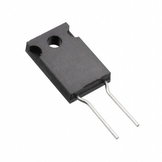
| 描述 | RES 1 OHM 35W 1% TO220厚膜电阻器 - 透孔 1ohm 35W 1% TOL Thru Hole |
| 产品分类 | |
| 品牌 | Bourns |
| 产品手册 | |
| 产品图片 |
|
| rohs | 符合RoHS无铅 / 不受限制有害物质指令(RoHS)规范要求限制 |
| 产品系列 | 薄膜电阻器,厚膜电阻器 - 透孔,Bourns PWR220T-35-1R00FPWR220T-35 |
| mouser_ship_limit | 该产品可能需要其他文件才能进口到中国。 |
| 数据手册 | |
| 产品型号 | PWR220T-35-1R00F |
| RoHS指令信息 | |
| 产品 | Thick Film Resistors Leaded |
| 产品培训模块 | http://www.digikey.cn/PTM/IndividualPTM.page?site=cn&lang=zhs&ptm=25810 |
| 产品种类 | 厚膜电阻器 - 透孔 |
| 供应商器件封装 | TO-220-2 |
| 其它名称 | PWR220T351R00F |
| 功率(W) | 35W |
| 功率额定值 | 35 W |
| 包装 | 管件 |
| 商标 | Bourns |
| 外壳宽度 | 4 mm |
| 外壳长度 | 10.1 mm |
| 外壳高度 | 14.6 mm |
| 大小/尺寸 | 0.398" 长 x 0.157" 宽(10.10mm x 4.00mm) |
| 容差 | 1 % |
| 封装 | Tube |
| 封装/外壳 | TO-220-2 |
| 工作温度范围 | - 55 C to + 155 C |
| 工厂包装数量 | 50 |
| 引线间隔 | 5.08 mm |
| 成分 | 厚膜 |
| 标准包装 | 50 |
| 温度系数 | 100 PPM / C |
| 特性 | 获得 AEC-Q200 汽车认证, 电流感应, 防脉冲 |
| 电压额定值 | 2 kV |
| 电阻 | 1 Ohms |
| 电阻(Ω) | 1 |
| 端子数 | 2 |
| 端接类型 | Radial |
| 类型 | Power Resistors |
| 系列 | PWR220T-35 |
| 高度 | 0.575"(14.60mm) |


- 商务部:美国ITC正式对集成电路等产品启动337调查
- 曝三星4nm工艺存在良率问题 高通将骁龙8 Gen1或转产台积电
- 太阳诱电将投资9.5亿元在常州建新厂生产MLCC 预计2023年完工
- 英特尔发布欧洲新工厂建设计划 深化IDM 2.0 战略
- 台积电先进制程称霸业界 有大客户加持明年业绩稳了
- 达到5530亿美元!SIA预计今年全球半导体销售额将创下新高
- 英特尔拟将自动驾驶子公司Mobileye上市 估值或超500亿美元
- 三星加码芯片和SET,合并消费电子和移动部门,撤换高东真等 CEO
- 三星电子宣布重大人事变动 还合并消费电子和移动部门
- 海关总署:前11个月进口集成电路产品价值2.52万亿元 增长14.8%
PDF Datasheet 数据手册内容提取
*RoHS VCEOARVMSIAPILOLINAASBNLTE *RoHS COMPLIANT LEAD FREE LVEREAoRDH SISF ORCNEOSE MAPRLIE ANT* Features Applications *&R oAHESC -CQO20M0P LQIUAANLTIFIED nn TLOow-2 i2n0d uhcotuasnicneg nn PMoowtoerr dsruivpepslies 1622 n Resistor electrically isolated from the n Test and measurement AEC *ARPoPHRS OCVOEMD P(LSIeAleNcTt Models) nnn bHARaEiogcCHhk-Sp Qp lca2oot0wem0e rpq rluiaaatnliintfi*ged n Rectifiers PWR220T-35 Series Power Resistor General Information Bourns® PWR220T-35 Series is a TO-220 DPAK style power resistor. Manufactured using thick film on alumina ceramic technology, it is used in current measurement, snubber, bleeder and discharge circuits. Electrical & Thermal Characteristics Popular Resistance Values Parameter Value(s) Code Resistance Code Resistance Value Value Resistance (See Popular Resistance Values table) 0.02 Ω to 130 KΩ R020 0.02 Ω*** 1000 100 Ω Power Rating @ 25 ˚C Case Temperature 35 W R025 0.025 Ω*** 1200 120 Ω Tolerance ±1 %**, ±5 % R030 0.03 Ω*** 1500 150 Ω TCR R033 0.033 Ω*** 2000 200 Ω 0.02 Ω<R<130.0K Ω ±100 PPM/˚C R040 0.04 Ω*** 2500 250 Ω R050 0.05 Ω*** 3000 300 Ω Thermal Resistance - Rthj 3.7 ˚C/W R075 0.075 Ω*** 3300 330 Ω Inductance 0.1 µH maximum R100 0.1 Ω 4000 400 Ω Operating Voltage √P*R with a maximum of 250 V R150 0.15 Ω 4700 470 Ω Dielectric Strength 2 KV AC R200 0.2 Ω 5000 500 Ω Insulation Resistance 10 GΩ R250 0.25 Ω 5600 560 Ω R300 0.3 Ω 7500 750 Ω Operating Temperature -55 ˚C to 155 ˚C R330 0.33 Ω 1001 1.0 KΩ ** Available for most values. Check Popular Resistance Values table. R400 0.4 Ω 1501 1.5 KΩ R500 0.5 Ω 2001 2.0 KΩ R750 0.75 Ω 2501 2.5 KΩ Reliability Characteristics 1R00 1 Ω 3001 3.0 KΩ 1R50 1.5 Ω 3301 3.3 KΩ Parameter Specification 2R00 2 Ω 4001 4.0 KΩ Short Term Overload (2x Pr for R < 2 Ω, ΔR ±0.25 % 2R50 2.5 Ω 5001 5.0 KΩ 1.6 x Pr for R ≥ 2 Ω, V < 1.5 x Operating Voltage) 3R00 3 Ω 7501 7.5 KΩ Load Life (1000 hours at rated power) ΔR ±1.0 % 3R30 3.3 Ω 1002 10 KΩ Thermal Shock (-55 ˚C to 155 ˚C, 5 cycles) ΔR ±0.5 % 4R00 4 Ω 1502 15 KΩ Resistance to Soldering Heat (10 seconds at 5R00 5 Ω 2002 20 KΩ ΔR ±0.5 % 270 ˚C) 7R50 7.5 Ω 2502 25 KΩ Vibration (20 G 10-2000 Hz .06 ” D.A.) ΔR ±0.25 % 8R00 8 Ω 3002 30 KΩ 10R0 10 Ω 3302 33 KΩ Terminal Strength (MIL-STD-202, Method 211 ΔR ±0.2 % 12R0 12 Ω 4002 40 KΩ Test A1) 15R0 15 Ω 4702 47 KΩ Shock (Saw Tooth: 100 g/6 ms) ΔR ±0.5 % 20R0 20 Ω 5002 50 KΩ Humidity (Steady State) 1000 hrs. 85 °C/85 % RH ΔR ±0.5 % 25R0 25 Ω 5602 56 KΩ High Temperature Exposure 27R0 27 Ω 6802 68 KΩ ΔR ±0.5 % (100 hrs - 40 % Pr @ +125 °C) 30R0 30 Ω 7502 75 KΩ 33R0 33 Ω 8202 82 KΩ 40R0 40 Ω 1003 100 KΩ Material Characteristics Typical Part Marking 47R0 47 Ω 1153 115 KΩ Resistor ...................................Thick film 50R0 50 Ω 1203 120 KΩ Substrate .....................Alumina (AL203) 56R0 56 Ω 1253 125 KΩ Housing ........................................Epoxy 75R0 75 Ω 1303 130 KΩ MODEL Pins....................Tinned Copper (Sn/Cu) NUMBER Flammability ........Conforms to UL-94V0 RESISTANCE 220 35 *** 5 % Tolerance CODE R500 1% TOLERANCE MANUFACTURER'S YYWW DATE CODE Packaging TRADEMARK COSTA RICA COUNTRY OF ORIGIN ............................................50 pcs./tube *RoHS Directive 2002/95/EC Jan. 27, 2003 including annex and RoHS Recast 2011/65/EU June 8, 2011. Specifications are subject to change without notice. The device characteristics and parameters in this data sheet can and do vary in different applications and actual device performance may vary over time. Users should verify actual device performance in their specific applications.
PWR220T-35 Series Power Resistor Product Dimensions How to Order 44..00 PWR 220 T - 35 - 10R0 F ((..115588)) ((1.1.330099..1818)) ((..3131.4.46622))DDIIAA.. 11..2233 M odPeWl R = Power Resistor ((..004499)) Package 220 = TO-220 Style Pin Style 66..00 ((..223366)) 22..55 T = Through-hole ((..009988)) Power 1144..66 35 = 35 W ((..557755 Resistance Value <100 ohms ...“R” represents decimal point 88..6633 (examples: 7R50 = 7.5 Ω; R500 = 0.5 Ω) ((..334400)) ≥100 ohms ....First three digits are significant, fourth digit represents number of zeros to follow (examples: 2000 = 200 ohms; 3002 = 30K ohms) Absolute Tolerance J = 5 % F = 1 % 1133..7722 2288..33 ((..554400)) ((11..1122)) RREEFF.. Derating Curve 120 100 55..0088 ((0.0.00..72722929)) ((2.2.00..28285959)) o (%) 80 ((..220000)) Rati 60 D IMENSIONS: (INMCHMES) Power 40 0.38 20 TOLERANCE: ± UNLESS OTHERWISE NOTED (0.015) 0 -20 25 35 45 55 65 75 85 95 105 115 125 135 145 155 Pulse Power Rating Temperature of Backplate (°C) 100 s ule 10 o J n y i 1 g er n E 0.1 0.01 10-7 10-6 10-5 10-4 10-3 10-2 10-1 Overload Duration in Seconds The energy absorbed by the resistor expressed in Joules can be calculated by multiplying the peak power of the pulse in watts times the length of the pulse in seconds. The energy should not exceed the limits shown in the graph. The overload voltage should not exceed 1.5 times the maximum operating voltage. REV. 07/16 Specifications are subject to change without notice. The device characteristics and parameters in this data sheet can and do vary in different applications and actual device performance may vary over time. Users should verify actual device performance in their specific applications.