
 Datasheet下载
- 型号: PTH05020WAD
- 制造商: Texas Instruments
- 库位|库存: xxxx|xxxx
- 要求:
| 数量阶梯 | 香港交货 | 国内含税 |
| +xxxx | $xxxx | ¥xxxx |
查看当月历史价格
查看今年历史价格
PTH05020WAD产品简介:
ICGOO电子元器件商城为您提供PTH05020WAD由Texas Instruments设计生产,在icgoo商城现货销售,并且可以通过原厂、代理商等渠道进行代购。 PTH05020WAD价格参考。Texas InstrumentsPTH05020WAD封装/规格:直流转换器, 非隔离 PoL 模块 DC/DC 转换器 1 输出 0.8 ~ 3.6V 22A 4.5V - 5.5V 输入。您可以下载PTH05020WAD参考资料、Datasheet数据手册功能说明书,资料中有PTH05020WAD 详细功能的应用电路图电压和使用方法及教程。
Artesyn Embedded Technologies的PTH05020WAD是一款非隔离式DC/DC降压(Buck)转换器模块,广泛应用于需要高效、稳定直流电压转换的场合。该模块输入电压范围较宽,通常为4.5V至14V,输出电压可通过外部电阻调节,适用于多种嵌入式和工业应用场景。

主要应用场景包括:

1. 通信设备:如基站、路由器、交换机等,用于为FPGA、ASIC、处理器等提供稳定的中间总线电压。

2. 工业自动化系统:用于PLC、工业控制计算机、传感器系统中,为各种低压电子元件提供精确供电。

3. 测试与测量仪器:为高精度仪表中的模拟和数字电路提供低噪声、高稳定性的电源。

4. 医疗电子设备:如诊断设备、便携式监护仪等,适用于对电源可靠性与稳定性要求较高的场合。

5. 嵌入式计算平台:如单板计算机、边缘计算设备,为系统中的多路电源轨提供灵活的电压转换方案。

该模块具备过流、过温保护功能,支持快速动态响应,适合在复杂电磁环境和较高温度条件下稳定运行。
| 参数 | 数值 |
| 品牌 | Texas Instruments |
| 产品目录 | |
| 描述 | 非隔离式DC/DC转换器 22A 5V-In Wide-Out Adj Plug-in Pwr Mdl |
| 产品分类 | DC/DC转换器 |
| 产品手册 | |
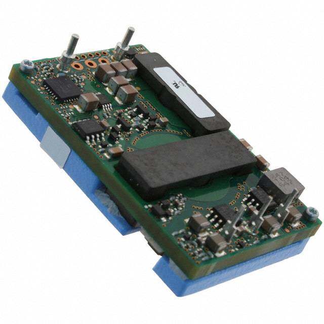
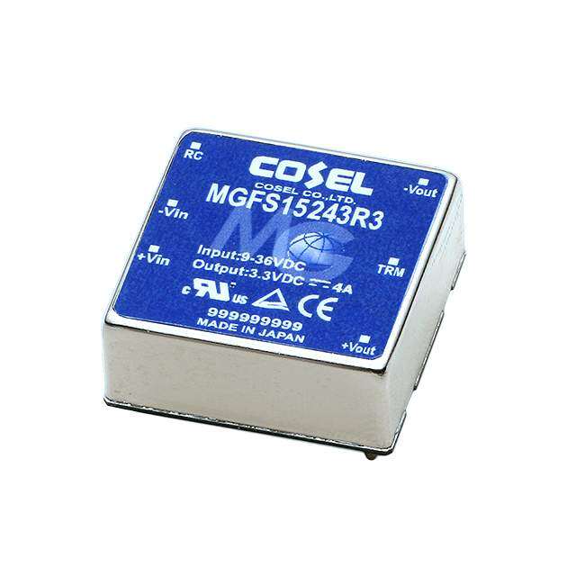
| 产品图片 |
|
| rohs | 符合RoHS |
| 产品系列 | 非隔离式DC/DC转换器,Texas Instruments PTH05020WAD |
| 产品型号 | PTH05020WAD |
| 产品 | Non-Isolated / POL |
| 产品种类 | 非隔离式DC/DC转换器 |
| 商标 | Texas Instruments |
| 安装风格 | Through Hole |
| 宽度 | 22.1 mm |
| 封装 | Tube |
| 封装/箱体尺寸 | DIP-10 Module |
| 尺寸 | 38.1 mm x 22.1 mm x 8.9 mm |
| 工作温度范围 | - 40 C to + 85 C |
| 工厂包装数量 | 20 |
| 系列 | PTH05020W |
| 输入电压—公称值 | 5 V |
| 输入电压范围 | 4.5 V to 5.5 V |
| 输出功率 | 79 W |
| 输出电压—通道1 | 0.8 V to 3.6 V |
| 输出电流—通道1 | 22 A |
| 输出端数量 | 1 |
| 长度 | 38.1 mm |
| 高度 | 8.9 mm |


- 商务部:美国ITC正式对集成电路等产品启动337调查
- 曝三星4nm工艺存在良率问题 高通将骁龙8 Gen1或转产台积电
- 太阳诱电将投资9.5亿元在常州建新厂生产MLCC 预计2023年完工
- 英特尔发布欧洲新工厂建设计划 深化IDM 2.0 战略
- 台积电先进制程称霸业界 有大客户加持明年业绩稳了
- 达到5530亿美元!SIA预计今年全球半导体销售额将创下新高
- 英特尔拟将自动驾驶子公司Mobileye上市 估值或超500亿美元
- 三星加码芯片和SET,合并消费电子和移动部门,撤换高东真等 CEO
- 三星电子宣布重大人事变动 还合并消费电子和移动部门
- 海关总署:前11个月进口集成电路产品价值2.52万亿元 增长14.8%


PDF Datasheet 数据手册内容提取
PTH05020 5 Vin single output DC-DC CONVERTERS POLA Non-isolated 1 • 22 A output current NEW Product • 5 V input voltage • Wide-output voltage adjust (0.8 Vdc to 3.6 Vdc) • Auto-track™ sequencing* • Margin up/down controls • Pre-bias start-up capability • Efficiencies up to 96% • Output ON/OFF inhibit • Output voltage sense • Point-of-Load-Alliance (POLA) compatible • Available RoHS compliant The PTH05020 is a next generation series of non-isolated dc-dc converters offering some of the most advanced POL features available in the industry. The primary new feature provides for sequencing between multiple modules, a function, which is becoming a necessity for powering advanced silicon including DSP’s, FPGA’s and ASIC’s requiring controlled power-up and power-down Other industry leading features include margin up/down controls, pre-bias start-up capability and efficiencies up to 96%. The PTH05020 has an input voltage of 4.5 Vdcto 5.5 Vdcand offers a wide 0.8 Vdc to 3.6 Vdc output voltage range with up to 22 A output current, which allows for maximum design flexibility and a pathway for future upgrades. 2 YEAR WARRANTY All specifications are typical at nominal input, full load at 25 °C unless otherwise stated SPECIFICATIONS C = 1000 µF, C = 0 µF in out OUTPUT SPECIFICATIONS EMC CHARACTERISTICS Voltage adjustability (See Note 4) 0.8-3.6 Vdc Electrostatic discharge EN61000-4-2, IEC801-2 Conducted immunity EN61000-4-6 Setpoint accuracy ±2.0% Vo Radiated immunity EN61000-4-3 Line regulation ±5 mV typ. GENERAL SPECIFICATIONS Load regulation ±5 mV typ. Efficiency (See Efficiency Table) 96% max. Total regulation ±3.0% Vo Insulation voltage Non-isolated Minimum load 0 A Switching frequency 250 kHz to 340 kHz Ripple and noise 20 MHz bandwidth 20 mV pk-pk Approvals and EN60950 Temperature co-efficient -40 ºC to +85 ºC ±0.5% Vo standards UL/cUL60950 Transient response 70 µs recovery time Material flammability UL94V-0 (See Note 5) Overshoot/undershoot 120 mV Dimensions (Lx W x H) 37.97 x 22.10 x 9.00 mm Margin adjustment ±5.0% Vo 1.495 x 0.870 x 0.354 in INPUT SPECIFICATIONS Weight 7 g (0.25 oz) Input voltage range (See Note 3) 4.5-5.5 Vdc MTBF Telcordia SR-332 5,236,000 hours Input current No load 10 mA typ. ENVIRONMENTAL SPECIFICATIONS Remote ON/OFF (See Note 1) Positive logic Thermal performance Operating ambient, -40 ºC to +85 ºC Start-up time 1 V/ms (See Note 2) temperature Non-operating -40 ºC to +125 ºC Undervoltage lockout 3.7-4.3 Vdctyp. MSL (‘Z’ suffix only) JEDEC J-STD-020C Level 3 Track input voltage Pin 8 (See Note 6, 7) ±0.3 Vin PROTECTION Short-circuit Auto reset 41 Atyp. Thermal Auto recovery International Safety Standard Approvals UL/cUL CAN/CSA-C22.2 No. 60950-1-03/UL 60950-1, *Auto-track™ is a trade mark of File No. E174104 Texas Instruments TÜV Product Service (EN60950) Certificate No. B 04 06 38572 044 CBReport and Certificate to IEC60950, Certificate No. US/8292/UL File Name: pth05020.pdf Rev (07): 16 Dec 2005
PTH05020 5 Vin single output DC-DC CONVERTERS POLA Non-isolated 2 For the most current data and application support visit www.artesyn.com/powergroup/products.htm NEW Product OUTPUT OUTPUT OUTPUT INPUT OUTPUT EFFICIENCY REGULATION MODEL POWER CURRENT CURRENT (MAX.) VOLTAGE VOLTAGE (MIN.) (MAX.) (MAX.) LINE LOAD NUMBER (9,10) 79.2 W 4.5-5.5 Vdc 0.8-3.6 Vdc 0 A 22 A 96% ±5 mV ±5 mV PTH05020 Part Number System with Options P T H 0 5 0 2 0 W A S T Product Family Packaging Options Point of Load Alliance No Suffix = Trays Compatible T = Tape and Reel (8) Input Voltage Mounting Option (9) 05 = 5 V D = Horizontal Through-Hole (Matte Sn) H =Horizontal Through-Hole (Sn/Pb) S = Surface-Mount (63/37 Sn/Pb Output Current pin solder material) 02 = 22 A Z = Surface-Mount (96.5/3.0/0.5 Sn/Ag/Cu pin solder material) Mechanical Package Pin Option Always 0 A= Through-Hole Std. Pin Length (0.140”) A = Surface-Mount Tin/Lead Solder Ball Output Voltage Code W = Wide OOuuttppuutt VVoollttaaggee AAddjjuussttmmeenntt ooff tthhee PPTTHH0055002200 SSeerriieess The ultra-wide output voltage trim range offers major advantages to users who select the PTH05020. It is no longer necessary to purchase a variety of modules in order to cover different output voltages. The output voltage can be trimmed in a range of 0.8 Vdc to 3.6 Vdc. When the PTH05020 converter leaves the factory the output has been adjusted to the default voltage of 0.8 V. NNootteess EFFICIENCY TABLE (I = 10 A) O 1 Remote ON/OFF. Positive Logic ON: Pin 3 open; or V >Vin - 0.5 V OUTPUT VOLTAGE EFFICIENCY OFF: Pin 3 GND; or V <0.8 V (min - 0.2 V). 2 See Figure 1 for safe operating curve. Vo = 1.0 V 88% 3 A 1,000 µF electrolytic input capacitor is required for proper operation. The capacitor must be rated for a minimum of 700 mA rms of ripple Vo = 1.2 V 90% current. 4 An external output capacitor is not required for basic operation. Adding Vo = 1.5 V 91% 330 µF of distributed capacitance at the load will improve the transient response. Vo = 1.8 V 92% 56 1If uAt/iµlizse ldoa Vdo sutte wpi,l l5 t0ra tcok 1 a0p0p%lie Ido mvoaxlt,a Cgeou bty= ±303.03 µVF.(up to Vo set point). Vo = 2.0 V 93% 7 The pre-bias start-up feature is not compatible with Auto-Track™. This is because when the module is under Auto-Track™control, it is fully active Vo = 2.5 V 94% and will sink current if the output voltage is below that of a back-feeding source. Therefore to ensure a pre-bias hold-off, one of the following two Vo = 3.3 V 96% techniques must be followed when input power is first applied to the module. The Auto-Track™function must either be disabled, or the module’s output held off using the Inhibit pin. Refer to Application Note 156 for more details. 8 Tape and reel packaging only available on the surface-mount versions. 9 To order Pb-free (RoHS compatible) surface-mount parts replace the mounting option ‘S’ with ‘Z’, e.g. PTH05020WAZ. To order Pb-free (RoHS compatible) through-hole parts replace the mounting option ‘H’ with ‘D’, e.g. PTH05020WAD. 10 NOTICE: Some models do not support all options. Please contact your local Artesyn representative or use the on-line model number search tool at http://www.artesyn.com/powergroup/products.htm to find a suitable alternative. File Name: pth05020.pdf Rev (07): 16 Dec 2005
PTH05020 5 Vin single output DC-DC CONVERTERS POLA Non-isolated 3 For the most current data and application support visit www.artesyn.com/powergroup/products.htm NEW Product 90 80 100 C) E (º 70 %) 90 PERATUR 5600 N124000a000t cLLLoFFFnMMMv CIENCY ( 678000 321111......358520VVVVVV M 40 FI E F 50 T 30 E 40 20 0 2 4 6 8 10 12 14 16 18 20 22 0 2 4 6 8 10 12 14 16 18 20 22 OUTPUT CURRENT (A) OUTPUT CURRENT (A) Figure 1 - Safe Operating Area Figure 2 - Efficiency vs Load Current Vin = 5 V, Output Voltage = 3.3 V (See Note A) Vin = 5 V (See Note B) NNootteess Track Margin Down A SOA curves represent the conditions at which internal components are Margin Up within the Artesyn derating guidelines. B Characteristic data has been developed from actual products tested at 10 9 8 25 °C. This data is considered typical data for the converter. 1 7 PTH05020 (Top View) Vout Vin 2 6 3 4 5 Inhibit Vo Sense + C(Rine 1q0u0ir0eµdF) (RRSeETq 1u%ire,d 0).1W + C(Ooput t3io3n0aµlF) LOAD GND GND Figure 3 - Standard Application File Name: pth05020.pdf Rev (07): 16 Dec 2005
PTH05020 5 Vin single output DC-DC CONVERTERS POLA Non-isolated 4 For the most current data and application support visit www.artesyn.com/powergroup/products.htm NEW Product 1.495 (37.97) 0.125 (3.18) 0.140 0.125 (3.18) (3.55) 0.060 0.060 0.500 0.625 (15.88) (1.52) (1.52) (12.70) ø0.040 (1.02) 10 Places 1 10 9 8 7 (0.070 (1.78) (Standoff Shoulder) 0.750 0.870 (19.05) (22.10) PIN CONNECTIONS Lowest Component 0.010 min. (0.25) 3 4 5 Bottom side Clearance PIN NO. FUNCTION 2 6 1 Ground TOP VIEW Host Board 2 Vin 0.354 3 Inhibit* (9.00)max. Dimensions in Inches (mm) Side View 4 Vo adjust Tolerances (unless otherwise specified) 2 Places ±0.030 (±0.76) 5 Vo sense 3 Places ±0.010 (±0.25) 6 Vout Figure 4 - Plated Through-Hole Mechanical Drawing 7 Ground 8 Track 9 Margin down* 10 Margin up* 1.495 (37.97) 0.125 (3.18) *Denotes negative logic: 0.125 (3.18) 0.060 0.354 (9.00) *After solder reflow Open = Normal operation 0.060 0.500 0.625 (15.88) (1.52) max.* on customer board Ground = Function active (1.52) (12.70) 1 10 9 8 7 Solder Ball ø0.040 (1.02) 10 Places 0.870 0.750 (22.10) (19.05) 3 4 5 2 6 TOP VIEW SIDE VIEW Dimensions in Inches (mm) Tolerances (unless otherwise specified) 2 Places ±0.030 (±0.76) 3 Places ±0.010 (±0.25) Figure 5 - Surface-Mount Mechanical Drawing Datasheet © Artesyn Technologies®2005 The information and specifications contained in this datasheet are believed to be correct at time of publication. However, Artesyn Technologies accepts no responsibility for consequences arising from printing errors or inaccuracies. The information and specifications contained or described herein are subject to change in any manner at any time without notice. No rights under any patent accompany the sale of any such product(s) or information contained herein. Please consult our website for the following items: (cid:1) Application Note www.artesyn.com File Name: pth05020.pdf Rev (07): 16 Dec 2005