.jpg)
 Datasheet下载
- 型号: PT06A-12-4P(470)
- 制造商: Amphenol
- 库位|库存: xxxx|xxxx
- 要求:
| 数量阶梯 | 香港交货 | 国内含税 |
| +xxxx | $xxxx | ¥xxxx |
查看当月历史价格
查看今年历史价格
PT06A-12-4P(470)产品简介:
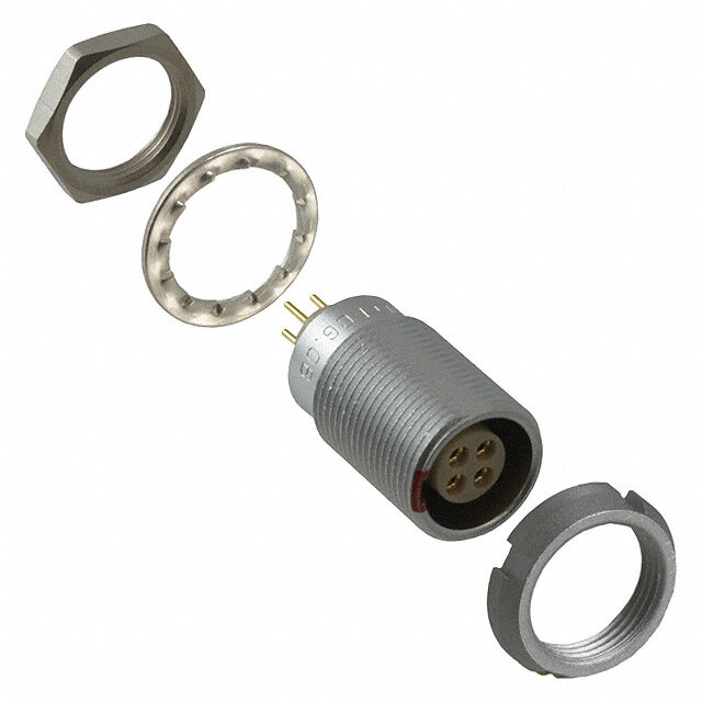
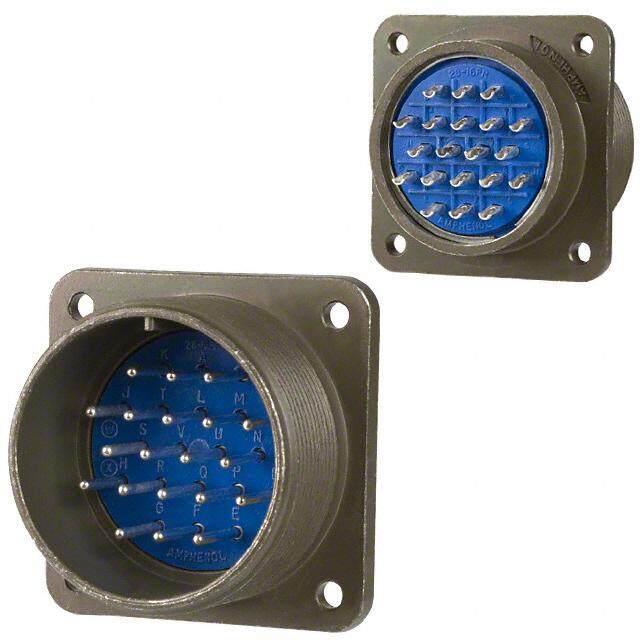
ICGOO电子元器件商城为您提供PT06A-12-4P(470)由Amphenol设计生产,在icgoo商城现货销售,并且可以通过原厂、代理商等渠道进行代购。 PT06A-12-4P(470)价格参考。AmphenolPT06A-12-4P(470)封装/规格:圆形连接器, 4 位置 圆形连接器 插头,公引脚 焊杯 金。您可以下载PT06A-12-4P(470)参考资料、Datasheet数据手册功能说明书,资料中有PT06A-12-4P(470) 详细功能的应用电路图电压和使用方法及教程。
Amphenol Industrial Operations的PT06A-12-4P(470)是一款圆形连接器,广泛应用于工业、军事和航空航天等领域。该型号属于MIL-DTL-5015标准系列,具备优良的机械性能与环境适应能力,适合在恶劣条件下稳定工作。

其主要应用场景包括:

1. 工业设备:用于自动化控制系统、机器人、生产线设备等,提供可靠的电力与信号传输。
2. 军事装备:如雷达系统、通信设备、军用车辆等,满足高可靠性与抗振动要求。
3. 航空航天:应用于飞机仪表、导航系统、地面支持设备中,适应高温、低温及震动环境。
4. 交通运输:如轨道交通车辆、重型机械设备,确保复杂环境中电连接的稳定性。
5. 能源与基础设施:用于发电设备、石油勘探仪器、远程监控系统等户外或极端工况场合。

该连接器具备螺纹锁紧结构,防松动设计,适用于需要频繁插拔或存在震动的场景。其4位插针配置支持多路电力或信号传输,适用于多种电气需求。
| 参数 | 数值 |
| 产品目录 | |
| 描述 | CONN PLUG 4POS W/PINS SOLDER |
| 产品分类 | |
| 品牌 | Amphenol Industrial Operations |
| 数据手册 | |
| 产品图片 |
|
| 产品型号 | PT06A-12-4P(470) |
| rohs | 无铅 / 符合限制有害物质指令(RoHS)规范要求 |
| 产品系列 | MIL-DTL-26482 系列 I,PT |
| 产品培训模块 | http://www.digikey.cn/PTM/IndividualPTM.page?site=cn&lang=zhs&ptm=25050 |
| 产品目录绘图 |
|
| 产品目录页面 | |
| 侵入防护 | - |
| 其它名称 | PT06A124P470 |
| 包装 | 散装 |
| 外壳尺寸-插件 | 12-4 |
| 外壳尺寸,MIL | - |
| 外壳材料,镀层 | 铝,镀黑色锌钴 |
| 安装类型 | 自由悬挂 |
| 工作温度 | -55°C ~ 125°C |
| 朝向 | N(正常型) |
| 标准包装 | 1 |
| 特性 | 应力消除 |
| 电压-额定 | 600VAC |
| 端接 | 焊杯 |
| 紧固类型 | 插销锁 |
| 触头镀层 | 金 |
| 触头镀层厚度 | - |
| 连接器类型 | 插头,公引脚 |
| 针脚数 | 4 |
| 额定电流 | 13A |
.jpg)

.jpg)

.jpg)
.jpg)


.jpg)

- 商务部:美国ITC正式对集成电路等产品启动337调查
- 曝三星4nm工艺存在良率问题 高通将骁龙8 Gen1或转产台积电
- 太阳诱电将投资9.5亿元在常州建新厂生产MLCC 预计2023年完工
- 英特尔发布欧洲新工厂建设计划 深化IDM 2.0 战略
- 台积电先进制程称霸业界 有大客户加持明年业绩稳了
- 达到5530亿美元!SIA预计今年全球半导体销售额将创下新高
- 英特尔拟将自动驾驶子公司Mobileye上市 估值或超500亿美元
- 三星加码芯片和SET,合并消费电子和移动部门,撤换高东真等 CEO
- 三星电子宣布重大人事变动 还合并消费电子和移动部门
- 海关总署:前11个月进口集成电路产品价值2.52万亿元 增长14.8%

.jpg)
.jpg)
PDF Datasheet 数据手册内容提取
Amphenol ® Miniature Cylindrical Connectors 12-070-15 Meets MIL-C-26482, Series 1 Specifications Amphenol Corporation Amphenol Industrial Operations Amphenol Aerospace 40-60 Delaware Avenue, Sidney, New York 13838-1395 Amphenol Phone: 800-678-0141 or 607-563-5011 Fax: 607-563-5157 www.amphenol-industrial.com
Table of Contents Page No. Proprietary/MIL-C-26482 Series 1 connectors Introduction, Amphenol® Miniature Cylindrical covered in this catalog are widely used in gen- General Information, Design Flexibility . . . . . . . . . . . . . . . . . . .1, 2 eral duty and environmental applications, Connector Selection Guide . . . . . . . . . . . . . . . . . . . . . . . . . . 3 both industrial and military. Insert availability . . . . . . . . . . . . . . . . . . . . . . . . . . . . . . . . 4, 5 Markets that use this family of connectors include: Insert availability Breakaway Twist Pull. . . . . . . . . . . . . . . . . . . . . . . 6 (cid:129) Instrumentation Alternate positioning . . . . . . . . . . . . . . . . . . . . . . . . . . . . . . . . 7 (cid:129) Monitoring Equipment Insert arrangement patterns . . . . . . . . . . . . . . . . . . . . . . . . . . 8-11 PT, SP, MS/PT Proprietary/MIL-C-26482, Series 1 Bayonet Coupling, (cid:129) Machine Tool, Factory Automation Solder Contacts (cid:129) Communications General Information, Specifications, Service Class . . . . . . . . . . . 12, 13 (cid:129) Geophysical PT00 (MS3110), SP00 wall mounting receptacle . . . . . . . . . . . . . . 14 (cid:129) Industrial Controls and Robotics PT01 (MS3111) cable connecting receptacle . . . . . . . . . . . . . . . . 15 (cid:129) Oil and Petrochemical Industries PT02 (MS3112) SP02 box mounting receptacle . . . . . . . . . . . . . . 16 (cid:129) Rail/Mass Transit PT06 (MS3116) SP06 straight plug . . . . . . . . . . . . . . . . . . . . . 17 (cid:129) Military/Aerospace PT07 (MS3114) SP07 jam nut receptacle. . . . . . . . . . . . . . . . . . 18 PT08E, SP08E 90 degree plug . . . . . . . . . . . . . . . . . . . . . . . 19 PT Connectors with Printed Circuit Board Contacts - If more information is needed concerning the con- box mount receptacle, jam nut receptacle. . . . . . . . . . . . . . . . . . 20 nectors covered in this publication, or if there are PTB, SPB thru bulkhead receptacle. . . . . . . . . . . . . . . . . . . . . 21 special application needs, please contact: General Information, Specifications - PT hermetic . . . . . . . . . . . . . 22 PTIH (MS3113H) hermetic solder mounting receptacle. . . . . . . . . . . 23 Amphenol Corporation PT02H hermetic box mounting receptacle . . . . . . . . . . . . . . . . . 24 Amphenol Aerospace PT07H (MS3114H) hermetic jam nut receptacle . . . . . . . . . . . . . . 25 Amphenol Industrial Operations PT Breakaway twist pull plug . . . . . . . . . . . . . . . . . . . . . . . . 26 40-60 Delaware Avenue PT, SP, MS/PT how to order . . . . . . . . . . . . . . . . . . . . . . . . 27 Sidney, New York 13838-1395 PT-SE, SP-SE, MS/PT-SE Proprietary/MIL-C-26482, Series 1 Bayonet Coupling, Telephone: 607-563-5011 Crimp Contacts Fax: 607-563-5351 General Information, Specifications, Service Class . . . . . . . . . . . 28, 29 PT00SE (MS3120), SP00SE wall mounting receptacle. . . . . . . . . . . 30 Please go to the Amphenol websites to view, MF00SE (MS3128) wall mounting receptacle. . . . . . . . . . . . . . . . 31 download and save this catalog and most all of PT01SE (MS3121) SP01SE cable connecting receptacle . . . . . . . . . 32 Amphenol interconnection product literature. PT02SE (MS3122) SP02SE box mounting receptacle . . . . . . . . . . . 33 www.amphenol-industrial.com MF02SE (MS3127) box mounting receptacle . . . . . . . . . . . . . . . . 34 PT06SE (MS3126), SP06SE straight plug . . . . . . . . . . . . . . . . . 35 www.amphenol-aerospace.com PT07SE (MS3124) SP07SE jam nut receptacle . . . . . . . . . . . . . . 36 PT08SE, SP08SE 90 degree plug . . . . . . . . . . . . . . . . . . . . . 37 PT-SE Breakway twist pull plug . . . . . . . . . . . . . . . . . . . . . . . 38 Some miniature connector styles PT-CPGET,e -SnSePEr-a,C lS EInP Bf-oSaryEmo,a nMteiotS nC/P,o STupp-SleinEcgi fh,i coCawrtiim otonp s oC,r oSdneetrrav c i.tc se . C. l a. s .s .. .. .. .. .. .. .. .. .. .. .. .4 0. , 3491 averers aiovnasil.a Pblleea inse R cooHnSta cCto Ammpplihaennt ol ARmopHheSnol PT00CE, SP00CE wall mounting receptacle . . . . . . . . . . . . . . . . 42 Industrial Operations for more PT01CE, cable connecting receptacle . . . . . . . . . . . . . . . . . . . 43 information. EU/2002/95/EC PT02CE, SP02CE box mounting receptacle . . . . . . . . . . . . . . . . 44 PT06CE, SP06CE straight plug . . . . . . . . . . . . . . . . . . . . . . . 45 PT07CE, SP07CE jam nut receptacle. . . . . . . . . . . . . . . . . . . . 46 PT08CE, SP08CE 90 degree plug . . . . . . . . . . . . . . . . . . . . . 47 Amphenol operates Quality Systems that are cer- PT-CE Breakawat twist pull plug . . . . . . . . . . . . . . . . . . . . . . 48 tified to ISO9001: 2000 by third party registrars. PT-CE, SP-CE how to order. . . . . . . . . . . . . . . . . . . . . . . . . 49 PC Threaded Coupling, Solder Contacts General Information, Specifications, Service Class . . . . . . . . . . . 50, 51 PC00 wall mounting receptacle . . . . . . . . . . . . . . . . . . . . . . . 52 NOTE: PC01 cable connecting receptacle . . . . . . . . . . . . . . . . . . . . . 53 The connector products in this brochure were formerly PC02 box mounting receptacle . . . . . . . . . . . . . . . . . . . . . . . 54 known as Bendix® products. These products are now PC06 straight plug. . . . . . . . . . . . . . . . . . . . . . . . . . . . . . 55 manufactured and sold under the Amphenol® brand PC07 jam nut receptacle . . . . . . . . . . . . . . . . . . . . . . . . . . 56 name. The name “Amphenol” will replace the name General Information, Specifications - PC hermetic . . . . . . . . . . . . . 57 “Bendix” on products and literature in the future. PCIH hermetic solder mounting receptacle . . . . . . . . . . . . . . . . . 58 NOTE: PC02H hermetic box mounting receptacle . . . . . . . . . . . . . . . . . 59 The Miniature MIL-C-26482, Series 2 connectors PTS- PC07H hermetic jam nut receptacle. . . . . . . . . . . . . . . . . . . . . 60 DR and MS/PTS-DR (formerly in this catalog) are no PC how to order. . . . . . . . . . . . . . . . . . . . . . . . . . . . . . . 61 longer supplied with these designations. Amphenol now PC-SE, PC-CE Threaded Coupling, Crimp Contacts General Information, Specifications, Service Class . . . . . . . . . . . . . 62 supplies the Amphenol®/Matrix® MIL-C-26482, Series PC-SE, PC-CE how to order . . . . . . . . . . . . . . . . . . . . . . . . 63 2. (Military numbers include MS3470 - MS3472, Accessories. . . . . . . . . . . . . . . . . . . . . . . . . . . . . . . . . . 64-68 MS3474, - MS3476). Application tools . . . . . . . . . . . . . . . . . . . . . . . . . . . . . . . . . 69 Please refer to page 78 for a brief description of the Contacts, Power and Thermocouple Crimp. . . . . . . . . . . . . . . . . . . . 70 Amphenol®/Matrix® MIL-C-26482, Series 2 bayonet Contacts, Shielded Coax . . . . . . . . . . . . . . . . . . . . . . . . . . . 71-76 coupling connectors with crimp, rear insertable and rear Mounting Recommendations . . . . . . . . . . . . . . . . . . . . . . . . . . . 77 releasable contacts, and ask for catalog 12-071 for Other Amphenol Miniature Cylindrical Connectors . . . . . . . . . . . . . . 78, 79 detailed information on this series. Amphenol Sales Office and Authorized Distributor Listing . . . . . . . . . . . . 80
Amphenol ® Miniature Cylindrical Connectors Proprietary/MIL-C-26482, Series 1 Amphenol® Miniature Cylindrical connectors offer twice the number of contacts in just half the size of a Standard connector. These miniature connectors, are available in several series, each with varying design characteristics and customer options to meet cost con- siderations and provide maximum design flexibility. There are two styles within the family that are MS approved and qualified to MIL- C-26482, Series 1, and in addition there are several proprietary styles. Common features of all styles: (cid:129) All are for general duty applications and environmental sealing is achieved with the grommet and clamp design. (cid:129) Operating temperature is from –55°C to +125°; Operating voltage to 1000 VAC (RMS) at sea level. (cid:129) Pin and socket contacts are machined from low loss copper alloy and gold plated to eliminate contact corrosion and provide an indefinite shelf life. (cid:129) All have resilient inserts which provide high dielectric strength and moisture barrier. (cid:129) A variety of shell finishes (including non-cadmium) and a variety of backend accessories are available within the styles. Bayonet Coupling with Solder Contact Termination PT, MS/PT (solder) Options (cid:129) MS and proprietary versions (cid:129) 7 shell styles with 60 insert patterns (cid:129) Factory installed solder contacts (cid:129) Hermetic seal (glass fusion) recepta- (cid:129) 3 point bayonet coupling and 5 key/keyway mating. cle styles available (cid:129) Intermateable with all miniature series connectors except threaded (cid:129) Pressurized thru bulkhead recepta- PC series. cle style available PT Solder (cid:129) MS/PT meets MIL-C-26482 Series 1, service classes E, F and P. (cid:129) Breakaway quick disconnect styles jam nut receptacle and (cid:129) MS/PT is UL recognized. (cid:129) EMI filter protection styles mated straight plug SP (solder) (cid:129) Pre-installed coax solder contacts (cid:129) SP Series is a modification of the PT with same features except a are available wider flange for back panel mounting (cid:129) Printed circuit board contacts are available Bayonet Coupling with Crimp Contact Termination PT-SE, MS/PT-SE (crimp) Options (cid:129) MS and proprietary versions (cid:129) 6 shell styles with 47 insert patterns PT Solder (cid:129) Crimp rear insertable/front release contact termination. (closed entry (cid:129) Breakaway quick disconnect style wall mount receptacle socket insert prevents probe damage). available (cid:129) 3 point bayonet coupling and 5 key/keyway mating. (cid:129) Coax and thermocouple contacts are (cid:129) Intermateable with all miniature series connectors except threaded available PC series. (cid:129) MS/PT-SE meets MIL-C-26482 Series 1, service classes E, F, P. SP-SE (crimp) (cid:129) Modification of the PT-SE with wider flange for back panel mounting PT-CE, SP-CE (crimp) (cid:129) Incorporates a special one-piece insert and grommet assembly PT-SE Crimp wall mount receptacle Threaded Coupling with Solder Contact Termination and mated straight plug PC (solder) Proprietary Options (cid:129) Double stub threaded coupling and single hole polarization. (cid:129) 5 shell styles with 60 insert patterns (cid:129) Factory installed solder contacts (cid:129) Hermetic receptacles available (cid:129) Pressurized thru bulkhead recepta- cle style available (cid:129) Pre-installed coax solder contacts are available. Threaded Coupling with Crimp Contact Termination Two threaded PC styles are offered in some shell sizes. Both have Options crimp front release and front removable contacts, but they have differ- (cid:129) 5 shell styles (consult Amphenol for ent retention systems. availability of shell sizes and insert PC-SE (crimp) Proprietary - with spring tower retention system patterns) (cid:129) Spring tower retention system PC Threaded Crimp PC-CE (crimp) Proprietary - with nylon wafer dielectric system straight plug and wall mount receptacle 1
Amphenol ® Miniature Cylindrical design flexibility The large family of miniature proprietary and MS style connectors provides for many optional features and designs. In addition to the choices of bayonet or threaded shells, solder or crimp termination within the style variations, there are additional options that are shown here. Hermetics Hermetically sealed receptacles have fused compression glass sealed inserts which provide envionrmental moisture sealing. There are three hermetic styles within the PT bayonet series and three hermetic styles within the PC threaded series. Coaxial Contacts Amphenol Miniature connectors can incorporate shielded coax contacts. Size 8 and 12 crimp coax contacts are available in PT-SE, 26482 Connector with Hermetic 26482 Connector with PC Tail SP-SE, MS/PT-SE. Factory installed size 8 and 12 solder type coax Seal Insert and Coax Contacts Contacts contacts are available in PT, SP,MS/PT connectors. See coax contact information pages at the end of this catalog. Printed Circuit Board Tail Contacts PT bayonet connectors in box mounting receptacle and jam nut receptacle styles are avail- able with printed circuit board contacts. Standard PCB tails for MIL-C-26482 connectors have gold plating, .0050 inches over nickel. See page 20 and call Amphenol for further infor- mation. Flex Circuitry Flex termination assemblies for attaching cylindrical connectors to printed circuit boards are available through the Amphenol division ACT, Advanced Circuit Technology. Flex can be used with miniature 26482 connectors and it can be designed to meet specific length, current 26482 Connector with Flex carrying capacity and to fit the precise geometric shape of the connector to board package. Flex circuity plugs into a printed circuit board and creates a self-locking terminal pad which eliminates the need for an additional interconnect to the PCB. Breakaway, Twist Pull Miniatures Quick disconnect “breakaway” styles are shown in this catalogs. These are available in PT solder style plugs (page 26), PT-SE crimp style plugs (page 38) or PT-CE crimp style plugs (page 48). Quick disconnect of the connector plug from the receptacle is accomplished with axial pull on the lanyard. This instant decoupling and damage free separation is ideal for weapons release and blind or difficult accessibility situations. Separation forces vary per connector series. The plug and receptacle need to be fully mated before disengagement by the lanyard pull. Breakaway Twist Pull 26482 Filter Protection Amphenol offers the FPT Series which combines the miniature PT series with an EMI filter. Designed to provide EMI protection for sensitive circuits, each circuit is individually filtered within the con- nector, eliminating the need for costly and bulky exterior network filters. Filter contacts are available in MF, HF, VHF, and UHF ranges and are intermateable and intermountable with MIL-C- 26482 connectors. For further information see catalog 12-120, Amphenol EMI Filter Transient Protection Connectors. (online at 26482 Connector with EMI www.amphenol-aerospace.com). Filter Protection Overmolded Cable 26482 Connector with Overmolded Cable Overmold seals and cables can be designed for almost any industrial application. A variety of materials are available: neoprene, hypalon and others; and a variety of lengths can be designed to meet customer specifications. Overmold seals to the rear of the connector and to the cable jacket providing moisture sealing. 2
Amphenol ® Miniature Cylindrical connector selection guide The accompanying chart is provided to assist the user in selecting the appropriate type of miniature connector to meet the application requirements. Further information can be found in specific sections of this catalog. Solder Crimp MS/ CHARACTERISTICS PT MS/PT SP PC PT-SE PT-SE SP-SE PC-SE PT-CE SP-CE PC-CE Intermateable† o o o X o o o X o o X Contacts Solder (cid:129) (cid:129) (cid:129) (cid:129) Crimp RI/FR (cid:129) (cid:129) (cid:129) (cid:129) (cid:129) (cid:129) (cid:129) Contact Retention Non-Removable (cid:129) (cid:129) (cid:129) (cid:129) System Removable (cid:129) (cid:129) (cid:129) (cid:129) (cid:129) (cid:129) (cid:129) Coupling Bayonet (cid:129) (cid:129) (cid:129) (cid:129) (cid:129) (cid:129) (cid:129) (cid:129) Threaded (cid:129) (cid:129) (cid:129) Standard Finishes†† Olive Drab Cadmium (003) (cid:129) (cid:129) (cid:129) (cid:129) (cid:129) Anodic Coated (005) (cid:129) (cid:129) (cid:129) Bright Cadmium (001) (cid:129) (cid:129) (cid:129) Temperature Range Resilient Dielectric (–55°C to +125°C) (cid:129) (cid:129) (cid:129) (cid:129) (cid:129) (cid:129) (cid:129) (cid:129) (cid:129) (cid:129) (cid:129) Wide Mounting Flange (cid:129) (cid:129) (cid:129) Hermetic Seal (cid:129) (cid:129) (cid:129) (cid:129) SHELL STYLE AVAILABILITY Wall Mounting Receptacle “00” (cid:129) (cid:129) (cid:129) (cid:129) (cid:129) **(cid:129) (cid:129) (cid:129) (cid:129) (cid:129) Cable Connecting Receptacle “01” *** (cid:129) (cid:129) (cid:129) (cid:129) (cid:129) (cid:129) (cid:129) (cid:129) Box Mounting Receptacle “02” *(cid:129) (cid:129) (cid:129) *(cid:129) (cid:129) **(cid:129) (cid:129) (cid:129) (cid:129) (cid:129) Straight Plug “06” (cid:129) (cid:129) (cid:129) (cid:129) (cid:129) (cid:129) (cid:129) (cid:129) (cid:129) (cid:129) (cid:129) Jam Nut Receptacle “07” *(cid:129) *(cid:129) (cid:129) *(cid:129) (cid:129) (cid:129) (cid:129) (cid:129) (cid:129) (cid:129) (cid:129) Thru-bulkhead Receptacle “TB” (cid:129) (cid:129) Solder Mount Receptacle “I” *(cid:129) *(cid:129) *(cid:129) 90° Plug “08” (cid:129) (cid:129) (cid:129) (cid:129) (cid:129) (cid:129) (cid:129) (cid:129) RI/FR = Rear Insertion/Front Releasable † o intermates with o X intermates with X †† Optional finishes available. See “how to order” sections. * Available in hermetic version ** Dual mounting holes *** This connector style is sometimes referred to as a cable connecting “plug.” It does, however, mate with either a straight or 90 degree plug. Amphenol®/Matrix® MIL-C-26482, Series 2 bayonet coupling connectors with rear insertable and rear releaseable contacts are covered in another catalog - See pageXX for a brief description and see complete details in catalog 12-071 which is online at www.amphenol-aerospace.com. 3
Amphenol ® Miniature Cylindrical insert availability Solder Termination Crimp Termination Contact Size Hermetic MS/PT-SE Coax PT PT-SE PT-CE Insert MS-PT SP-SE SP-CE Total Service Arrangement MS/PT PT SP PC PC PC-SE PC-CE Contacts 20 16 12 12 8 Rating 6-1 X X X X* 1 1 I 8-2 X X X X X X 2 2 I 8-3 X X X X X X 3 3 I 8-4 X X X X X X 4 4 I 8-33 X X X X X 3 3 I 8-98 X X X 3 3 I 10-2 X X X 2 2 I 10-5 X X X X* 5 5 I 10-6 X X X X X X X 6 6 I 10-70 X X X 1 1 Coax 10-98 X X X X X* X 6 6 I 12-3 X X X X X X X 3 3 II 12-4 X X X X* 4 4 I 12-8 X X X X X* X X 8 8 I 12-10 X X X X X X X 10 10 I 12-14 X X X 14 14 I 12-98 X X X 10 10 I 14-2 X X X 2 2 II 14-4 S S S X 4 4 I 14-5 X X X X X X X 5 5 II 14-8 X X X 8 6 2 I 14-12 X X X X X X X 12 8 4 I 14-15 X X X X X X X 15 14 1 I 14-18 X X X X X* X X 18 18 I 14-19 X X X X X X X 19 19 I 14-22 X* 5 1 4 I 14-71 P X X (02CE) 4 3 1 I 14-91 HV S X X X* 3 3 ** 14-AA X X X X 4 4 I 16-8 X X X X X X X 8 8 II 16-23 X X X X X X 23 22 1 I 16-26 X X X X X X X 26 26 I 16-70 X X X 15 14 1 N/A 16-76††† X* 14 8 1 5 *** 16-99 X X X X X 23 21 2 I 18-5 X X X X* 5 5 II 18-8 8 8 I 18-11 X X X X X X X 11 11 II 18-30 X X X X X* X X 30 29 1 I *Not available in MS version P designates Pin insert only. **Flashover voltage 5,000 VAC (RMS) †Size 12 contacts for #10 wire ***1500 VAC (RMS) ††Not presently tooled Sdesignates Socket insert only. †††Contacts must be ordered separately 4
IN S Amphenol ® Miniature Cylindrical E R T A insert availability, cont. V A IL A B IL IT Y Solder Termination Crimp Termination Contact Size Hermetic MS/PT-SE Coax PT PT-SE PT-CE Insert MS-PT SP-SE SP-CE Total Service Arrangement MS/PT PT SP PC PC PC-SE PC-CE Contacts 20 16 12 12 8 Rating 18-32 X X X X X X X 32 32 I 18-71 X* 9 8 1 Coax, II 18-72 X X X 14 10 4 N/A 18-75 X X X 4 4 Coax 18-76 4 3 1 II 18-80 X X X X 8 6 2 Coax, I 18-91 HV X* X 6 6 ** 20-16 X X X X X X X 16 16 II 20-24 X X X X X 24 24 I 20-25 X X X 25 25 I 20-26 X X X 26 20 6 I 20-27 X X X X X 27 27 I 20-39 X X X X X X X 39 37 2 I 20-41 X X X X X X X 41 41 I 20-70 14 10 4 Coax 20-90 HV X X X 7 7 Hi-Voltage 22-7 X X X X* 7 7 Coax 22-21 X X X X X X X 21 21 II 22-25 X* 25 25 I 22-32 X X X X X P 32 32 I 22-34 X X X X 34 34 I 22-36 X X X X 36 36 I 22-41 X X X X X X X 41 27 14 I 22-55 X X X X X X X 55 55 I 22-70 X X X 19 13 6 I, Coax 22-71 9 2 7 I, Coax 22-72 X X X 19 12 4 3 N/A 22-78††† X* 7 7 Coax 22-96 X* 7 7† II 24-31 X X X X 31 31 I 24-51 X* 51 47 4 I 24-61 X X X X X X X 61 61 I 24-71 X X X 49 45 2 2 N/A 24-79 6 1 5 Coax *Not available in MS version †Size 12 contacts for #10 wire **Flashover voltage 5,000 VAC (RMS) ††Not presently tooled ***1500 VAC (RMS) †††Contacts must be ordered separately 5
Amphenol ® Miniature Breakaway Twist Pull insert availability Insert Availability - Breakway Twist Pull For further information regarding any additional insert patterns available in Breakaway Miniature Crimp Solder connectors, please contact Amphenol Aerospace. Termination Termination Contact Size Insert Total Service For availability of shielded coax contacts within Arrangement PT-CE PT-SE PT Contacts 20 16 12 Rating Breakaway Miniature connectors contact Amphe- 8-2 X X 2 2 I nol.The Breakaway style pages are: PT (solder) 8-3 X X 3 3 I breakaway plug is on page 26, the PT-SE (crimp) 8-4 X X 4 4 I breakaway plug is on page 38, and the PT-CE 10-2 X 2 2 I (crimp) breakaway plug is on page 48. 10-6 X X X 6 6 I 10-98 X X 6 6 I 10-99 X X 7 7 I 12-3 X X X 3 3 II 12-4 X 4 4 I 12-8 X X X 8 8 I 12-10 X X X 10 10 I 12-98 X 10 10 I 14-2 X 2 2 II 14-5 X X X 5 5 II 14-8 X 8 6 2 I 14-12 X X X 12 8 4 I 14-15 X X X 15 14 1 I 14-16 X 4 2 2 II 14-18 X X X 18 18 I 14-19 X X X 19 19 I 14-91 X X 3 3* H.V. 16-6 X 6 6 I 16-8 X X X 8 8 II 16-23 X X X 23 22 1 I 16-26 X X X 26 26 I 16-99 X X 23 21 2 I 18-5 X X 5 5 II 18-11 X X X 11 11 II 18-28 X X 28 26 2 I 18-30 X X X 30 29 1 I 18-32 X X X 32 32 I 18-91 X X 6 6* H.V. 20-8 X 8 8 I 20-16 X X X 16 16 II 20-24 X X 24 24 I 20-25 X 25 25 I 20-27 X X 27 27 I 20-39 X X X 39 37 2 I 20-41 X X X 41 41 I 22-8 X 8 8 II 22-21 X X X 21 21 II 22-25 X 25 25 I 22-32 X X X 32 32 I 22-34 X X 34 34 I 22-36 X X 36 36 I 22-41 X X 41 27 14 I 22-55 X X X 55 55 I 22-96 X 7 7† II 22-97 X 16 16 II 22-99 X 11 11 II 24-31 X 31 31 I 24-61 X X X 61 61 I *5KV Voltage Rating 6 †Size 12 contact for #10 wire.
Amphenol ® Miniature Cylindrical alternate positioning Alternate Positioning To avoid cross-plugging problems in applications requiring the use of more than one miniature cylindrical connector of A A B B the same size and arrangement, alternate insert rotations B B A A are available as indicated in the accompanying chart. As shown in the diagram at right, the front face of the pin Position W Position X Position Y Position Z insert is rotated within the shell in a clockwise direction from the normal shell key. The socket insert would be rotated Views looking into front face of pin insert or rear of socket insert. counterclockwise the same number of degrees in respect to the normal shell key. Insert Rotation Insert Rotation Degrees Degrees Shell Insert Shell Insert Size Arrangement W X Y Z Size Arrangement W X Y Z 6 6-1 – – – – 18 18-11* 62 119 241 340 8 8-2* 58 122 – – 18 18-30* 180 193 285 350 8 8-3 60 210 – – 18 18-32* 85 138 222 265 8 8-4* 45 97 184 – 18 18-71 18 108 127 215 8 8-33* 90 – – – 18 18-72 53 102 213 293 8 8-98 – – – – 18 18-75 45 – – – 10 10-2 45 90 315 – 18 18-76 – – – – 10 10-5* 45 151 180 270 18 18-80 45 90 135 160 10 10-6* 90 – – – 18 18-91HV 90 180 240 270 10 10-70 – – – – 20 20-16* 238 318 333 347 10 10-98* 90 180 240 270 20 20-24 70 145 215 290 12 12-3* – – 180 – 20 20-25 72 144 216 288 12 12-4* 38 – – – 20 20-26 13 107 210 322 12 12-8 90 112 203 292 20 20-27 72 144 216 288 12 12-10* 60 155 270 295 20 20-39* 63 144 252 333 12 12-14 – – – – 20 20-41* 45 126 225 – 12 12-98* 61 135 189 340 20 20-70 63 135 222 335 14 14-2 58 122 – – 20 20-90 45 135 225 315 14 14-4* 45 – – – 22 22-7 19 41 – – 14 14-5* 40 92 184 273 22 22-21* 16 135 175 349 14 14-8 48 162 189 312 22 22-25 60 125 211 336 14 14-12* 43 90 – – 22 22-32 72 145 215 288 14 14-15* 17 110 155 234 22 22-34 62 142 218 298 14 14-18* 15 90 180 270 22 22-36 72 144 216 288 14 14-19* 30 165 315 – 22 22-41 39 135 264 – 14 14-22 45 – – – 22 22-55* 30 142 226 314 14 14-71 – – – – 22 22-70 30 82 218 312 14 14-91HV – 60 – – 22 22-71 33 191 236 270 14 14-AA* 45 – – – 22 22-72 42 200 277 339 16 16-8* 54 152 180 331 22 22-78 19 41 – – 16 16-23 158 270 – – 22 22-96* 19 41 – – 16 16-26* 60 – 275 338 24 24-31 90 225 255 – 16 16-70 41 122 216 286 24 24-51 22 171 313 – 16 16-76 – – – – 24 24-61* 90 180 270 324 16 16-99* 66 156 223 340 24 24-71 39 131 205 281 18 18-5 55 97 263 315 24 24-79 – – – – 18 18-8 180 – – – * Available in Hermetic Class 7
Amphenol ® Miniature Cylindrical insert arrangements front face of pin inserts illustrated CBA A D C C A C A B A B A B B B Insert Arrangement 6-1 8-2 8-3 8-4 8-33 8-98 10-2 Service Rating I I I I I I I Number of Contacts 1 2 3 4 3 3 2 Contact Size 20 20 20 20 20 20 16 E A F A A A G A D B E B E F B C A D B F H B C D C D C B C E D C Insert Arrangement 10-5 10-6 10-70 10-98 12-3 12-4 12-8 Service Rating I I Coax I II I I Number of Contacts 5 6 1 6 3 4 8 Contact Size 20 20 8 Coax 20 16 16 20 A G HKAJB C DA EB FCLHM HG A CB D A E A B H B F E D J NK P R FK EJD C B D C GF DC E Insert Arrangement 12-10 12-14 12-98 14-2 14-4 14-5 14-8 Service Rating I I I II I II I Number of Contacts 10 14 10 2 4 5 6 2 Contact Size 20 20 20 12 12 16 20 12 MG H JA BK J RK L AM BNC JKTML U ANPBC KL UMNVAPBRC B EA D A CB A F E L D C HG FP ED HGS F RED JHTG FS ED C D C B Insert Arrangement 14-12 14-15 14-18 14-19 14-22 14-71 14-91HV Service Rating I I I I I I Flashover 5,000 VAC (RMS) Number of Contacts 8 4 14 1 18 19 1 4 3 1 3 Contact Size 20 16 20 16 20 20 20 12 16 8 Coax 20 8 For contact legend see page 61.
Amphenol ® Miniature Cylindrical insert arrangements front face of pin inserts illustrated D A G HA B LMXYN PZR ASTBC MN aP RS bAT BUCD GN P AH JB C B F E D C KJWH VG FUED L KZYJ HcX GWVFE F ME LR DK C Insert Arrangement 14-AA 16-8 16-23 16-26 16-70 Service Rating I II I I N/A Number of Contacts 4 8 22 1 26 14 1 Contact Size 12 16 20 16 20 20 12 Coax A R A A J A K B P B A G B J N PL C NY S Z T UC E B H H K B M D H M D L X W V E D C F C G L C G E K F F J H G E D F E D Insert Arrangement 16-76 16-99 18-5 18-8 18-11 Service Rating Flashover I II I II 1.500 VAC (RMS) Number of Contacts 8 1 5 21 2 5 8 11 Contact Size 20 12* 2 Coax* 20 16 12 12 16 *Contact Positions Optional NMPLbRacKZdSgJ YAefTXBHUWCVGDFE NMPLcdRbKeSjaJhTUfHAZgVGYBWXFCED G FH EAJ BD C HJPGK F L NE ADMCB Insert Arrangement 18-30 18-32 18-71 18-72 Service Rating I I II, Coax N/A Number of Contacts 29 1 32 8 1 10 4 Contact Size 20 16 20 16 8 Coax 20 12 Coax A A A D B H B D A F C G C E B C B F D E D C Insert Arrangement 18-75 18-76 18-80 18-91 HV Service Rating Coax II I, Coax Flashover 5,000 VAC (RMS) Number of Contacts 4 3 1 6 2 6 Contact Size 8 Coax 12 Coax 8 Coax 20 8 Coax 20 9
Amphenol ® Miniature Cylindrical insert arrangements front face of pin inserts illustrated A L A L M A R B U V A K S M N B K W X N B N P X Y S C D R S Ta WB C D J R P C J V a Y P C M W b Z T E NP c b EF H D H U T Z S R D L V a U G F M L Z X H G G F E G F E K J H K Y J Insert Arrangement 20-16 20-24 20-25 20-26 Service Rating II I I I Number of Contacts 16 24 25 20 6 Contact Size 16 20 20 20 12 MN PYZ adR bA cSBTUC DE RSThUi jrV WkXAmYBZaCDE STUhVi Wrjs AXkt BmYCn ZDaEF P J K L A B M L K XJ WH VG F PNg fM qeL pK Jdn HcbGF R Pg fN qeM LdpKc JbHG H G F N E D C Insert Arrangement 20-27 20-39 20-41 20-70 Service Rating I I I Coax Number of Contacts 27 37 2 41 10 4 Contact Size 20 20 16 20 20 8 Coax A N A P A F B M P B N R B A G L W R C M Y Z S C G B E C K V X S D L XW b a U T D F E D C D J U T E K V E J F H F G H G Insert Arrangement 20-90 22-7 22-21 22-25 Service Rating Hi-Voltage Coax II I Number of Contacts 7 7 21 25 Contact Size 20 8 Coax 16 16 N A T A B S T A Y Z A B KLJMZYaHXbghf WPjGecdRVFSUTBECD NPRMbcSLdajkK lUZheJ gfYHV WGXC FDE NMP dLRec Kmlbf JaUngkHVZhj GBYWXCFED UTVSWRXihjP gksNr Mmqtf LaenpKbdcCJ DHEGF Insert Arrangement 22-32 22-34 22-36 22-41 Service Rating I I I I Number of Contacts 32 34 36 27 14 Contact Size 20 20 20 20 16 10
Amphenol ® Miniature Cylindrical insert arrangements front face of pin inserts illustrated PRkj Smzy TnGAFGFAUHBHBVpACDCDqWB XsrCaYZDE LK M T U V NA P B DC F H G A J B RJ K US AV TL B CM N i EE t F h x w v u c b J S R E H P F N D M g d G G E L f e H H F E C K J G D Insert Arrangement 22-55 22-70 22-71 22-72 Service Rating I I, Coax I, Coax N/A Number of Contacts 55 13 6 2 7 12 4 3 Contact Size 20 20 8 Coax 20 8 Coax 20 16 8 Coax A M A Z a A B A L N B Y b C F B F B Y Z a P Q X t u AAc d DE G K f b C W s y v e E G C J WX Ve gd Tc RS D VUT rqp x DDCCzBB w hgf HFG E D C D H G U F E S R nP mN kM j LiK J Insert Arrangement 22-78 22-96 24-31 24-51 Service Rating Coax II I I Number of Contacts 7 7 31 47 4 Contact Size 8 Coax 12 for 16 20 12 Coax # 10 wire VWXrsYt FZGuFGMaMNNvHPbHPJJwAKcKxdBy eCfgDEF VWpqX rYsyZBBt az AbAAucBdCefDEF D F A UT SqRpEEDnPDCNmCLLBMkB AjLAziKhJ HG UTSnRmPxkN wMj Liv KhJgHG C E B Insert Arrangement 24-61 24-71 24-79 Service Rating I N/A Coax Number of Contacts 61 45 2 2 1 5 Contact Size 20 20 16 8 Coax 20 8 Coax Contact Legend Symbol Contact Size 20 16 12 HV 12 Coax 8 Coax 11
Amphenol ® PT, SP, MS/PT Proprietary/MIL-C-26482, Series 1 bayonet coupling and solder termination Amphenol® solder contact miniature cylindrical connectors meet the most critical application needs. Design versatility combined with high reliability performance makes these series of Miniature Cylindrical Connectors ideal for environ- mental sealing or pressurized applications. wall mounting The MS/PT Series is qualified to MIL-C-26482, Series 1 and has receptacle all the outstanding design characteristics and quality of the PT Series. The SP Series is a modification of the PT, providing special shells with a wide mounting flange for back panel mounting. A corrosion resistant electrically conductive finish of cadmium plate with an olive drab chromate after-treatment is used on the PT and MS/PT. The SP is given a durable non-conductive hard anodic cable connecting “Alumilite”® coating which provides abrasion protection and resis- receptacle* tance to corrosion. Shell components for these series are aluminum. The dependable 5 key/keyway polarization with bayonet lock coupling assures pos- itive mating with no chance of cross plugging. Spring tension pro- vided by a wave washer in the coupling nut ensures maintenance of interfacial seal between mating halves. box mounting Both the insert and main joint gasket are molded from resilient neoprene. This provides excellent moisture sealing at the gasket receptacle and superior electrical isolation of the contact in the insert. Both pins and sockets are machined from a copper alloy and are gold plated. This gold plating eliminates contact corrosion and offers an indefinite shelf life. Socket contacts for these series are a closed entry design. A breakaway style plug is available in the PT solder series. Hermetics receptacles are available in PT and MS/ straight plug PT solder series. Receptacles with printed circuit board contacts are also available. PT Solder is UL recognized under file #E115497, Vol. 1, Sec. 5. The PT, SP and MS/PT Series are intermateable and intermount- able with all existing Miniature Cylindrical Series connectors except for the threaded coupling PC Series. jam nut receptacle Refer to pages 4-11 for insert arrangement availability. PT, SP, MS/PT CONTACT DATA/CONNECTOR RATINGS Contact Specifications Contact Test Maximum Solder Well Solder Well thru bulkhead Size Current Millivolt Drop† Diameter Depth receptacle +.004 +.031 20 7.5 55 .046 .125 –.000 –.000 +.005 +.031 16 13.0 50 .078 .188 –.003 –.000 +.004 +.031 12 23.0 42 .116 .188 –.002 –.000 breakaway Service Rating twist pull Recommended Test Voltage AC (RMS), 60 cps plug Operating Service AC Voltage Sea 50,000 70,000 110,000 Rating at Sea Level Level ft. ft. ft. I 600 1,500 500 375 200 II 1,000 2,300 750 500 200 †Silver plated wire per MIL-C-26482 * This connector style is sometimes referred to as a cable connecting 12 “plug.” It does, however, mate with a straight or 90 degree plug.
PT, SP Service Classes PT and SP connectors are available in the service classes listed below. Each class, with the exception of hermetic, offers one or more means of terminating or P WB sauvpapilaobrtlien gin a t hcea bSleP oSre wriieres. bundle. Class “W” is not T, S ITHAYO “A” General duty; back shell is threaded for con- “A” P, M SONE duit attachment of MS3057 cable clamp general duty S LT “A” (SR) General duty, with strain relief clamp for /PT DER CO cable or wire bundle support CUP “C” Pressurized receptacle; less than 1 cu. in. OL per hour leakage at 30 psi over a tempera- NTING ture range of –65°F to +257°F A C “E” Environmental resistant connectors - sup- T S plied with a multi-holed grommet and clamp- “E” (SR), ing nut for moisture-proofing individual open wires MS / “F” strain relief “E” (SR) Environmental resistant strain relief clamp and grommet for moisture proofing individual wires; provides added wire bundle support “J” Same as “W” class except with strain relief “P” Translucent nylon boot for retaining cus- tomer-applied potting compounds; held in place by a threaded ring “P” (SR) Strain relief clamp suitable for retaining cus- “E”, tomer applied potting compounds, with pro- MS / “E” vision for wire support open wire seal “W” Compressing clamp and neoprene gland for moisture proofing multi-conductor jacketed cables. Telescoping sleeves (MS 3420A) can be used to adapt to cables smaller than minimum close-down. “H”* Hermetically sealed with compression glass inserts (see pages 22-25) “P”, Style with printed circuit board contacts- see page 20. MS / “P” Breakaway style - see page 26. potting boot MS/PT Service Classes The MS/PT Miniature connector is available in the fol- lowing certified service classes: “E” Environmental resistant connectors - sup- plied with a multi-holed grommet and clamp- ing nut for moisture-proofing individual open “W” wires cable seal “F” Grommet seal with strain relief clamp “P” Translucent nylon boot for retaining cus- tomer-applied potting compounds; held in place by a threaded ring 13
PT00 (MS3110) SP00 wall mounting receptacle S PT L R .120 ± .005 Dia. M Q (TP) (.147 ± .005 Dia., size 24) SP .150 ± .005 Dia. 4 Holes R S A (TP) “W” Cable Seal K Z L TERMINATION ASSEMBLIES “A” General Duty/ “A” (SR), “E” (SR), “P” (SR), “E” Open Wire Seal “P” Potting Boot “C” Pressurized“ MS / “F” Strain Relief N D L V L L L PT00W-XX-XXX N D N GDH N N D “J” Cable Seal XL C .375 MIN PT00A-XX-XXX PT00A-XX-XXX (SR) PT00E-XX-XXX PT00P-XX-XXX SP00A-XX-XXX SP00A-XX-XXX (SR) SP00E-XX-XXX SP00P-XX-XXX PT00C-XX-XXX PT00E-XX-XXX (SR) MS3110E-XX-XXX MS3110P-XX-XXX N D SP00E-XX-XXX (SR) PT00P-XX-XXX (SR) SP00P-XX-XXX (SR) MS3110F-XX-XXX To complete part number see how to order on page 27. PT00J-XX-XXX ■ (MMC) located within .0025 of (TP) MS3110J-XX-XXX Receptacle Front View Receptacle Side View Class “A”, “C” R S A K +.020 M +.010 Q Z V Shell (TP) Max. +.001 –.010 L –.000 Thread Max. D L N Thread Size PT SP PT SP –.005 PT SP Max. PT SP Class 2A PT SP Min. Max. Max. Class A 6 .469 .641 .688 .953 .348 .493 .524 .906 .431 .462 .3125-32 NEF .468 .438 .175 1.553 .462 .3750-32 NEF 8 .594 .734 .812 1.047 .473 .493 .524 .906 .431 .462 .4375-28 UNEF .468 .438 .297 1.553 .590 .5000-28 UNEF 10 .719 .812 .938 1.125 .590 .493 .524 .906 .431 .462 .5625-24 NEF .468 .438 .421 1.553 .717 .6250-24 NEF 12 .812 .938 1.031 1.250 .750 .493 .524 .906 .431 .462 .6875-24 NEF .468 .438 .546 1.553 .834 .7500-20 UNEF 14 .906 1.031 1.125 1.344 .875 .493 .524 .906 .431 .462 .8125-20 UNEF .468 .438 .663 1.553 .970 .8750-20 UNEF 16 .969 1.125 1.219 1.438 1.000 .493 .524 .906 .431 .462 .9375-20 UNEF .468 .438 .787 1.553 1.088 1.0000-20 UNEF 18 1.062 1.203 1.312 1.516 1.125 .493 .524 .906 .431 .462 1.0625-18 NEF .531 .438 .879 1.553 1.216 1.1875-18 NEF 20 1.156 1.297 1.438 1.672 1.250 .650 .650 1.125 .556 .556 1.1875-18 NEF .531 .531 1.014 1.703 1.332 1.1875-18 NEF 22 1.250 1.375 1.562 1.750 1.375 .650 .650 1.125 .556 .556 1.3125-18 NEF .531 .531 1.134 1.703 1.460 1.4375-18 NEF 24 1.375 1.500 1.688 1.875 1.500 .683 .683 1.188 .589 .589 1.4375-18 NEF .498 .498 1.259 1.765 1.585 1.4375-18 NEF Class “A” (SR), “E” (SR), “P” (SR), MS / “F” Class “E”, MS / “E” Class “P”, MS / “P” Class “W”, “J” Shell C D G H L N L N D L N D L N XL Size Thread Min. Max. Max. Max. Max. Max. Max. Min. Max. Max. Closed Free Max. Max. Max. 6 – – – – – – 1.266 .440 .192 1.438 .484 – – – – – 8 6-32 .240 .125 .812 1.922 .550 1.266 .560 .317 1.438 .608 .168 .230 1.705 .547 2.271 10 6-32 .302 .188 .875 1.922 .675 1.266 .685 .434 1.438 .734 .205 .312 1.705 .675 2.271 12 6-32 .428 .312 1.000 1.922 .803 1.266 .813 .548 1.438 .858 .338 .442 1.848 .812 2.411 14 6-32 .552 .375 1.125 1.922 .920 1.266 .930 .673 1.438 .984 .416 .539 2.040 .940 2.599 16 6-32 .615 .500 1.188 2.047 1.047 1.266 1.057 .798 1.438 1.110 .550 .616 2.256 1.067 2.943 18 8-32 .740 .625 1.438 2.078 1.165 1.266 1.175 .899 1.438 1.234 .600 .672 2.486 1.194 3.172 20 8-32 .740 .625 1.438 2.344 1.290 1.516 1.301 1.024 1.656 1.360 .635 .747 2.922 1.322 3.610 22 8-32 .928 .750 1.625 2.344 1.418 1.516 1.430 1.149 1.656 1.484 .670 .846 3.086 1.449 3.766 24 8-32 .990 .800 1.719 2.406 1.543 1.578 1.555 1.274 1.717 1.610 .740 .894 3.310 1.576 3.985 All dimensions for reference only. 14
PT01 (MS3111) cable connecting receptacle L S M Q Y S A “W” Cable Seal L K Z TERMINATION ASSEMBLIES “A” General Duty “A” (SR), “E” (SR), “P” (SR), “E” Open Wire Seal “P” Potting Boot MS / “F” Strain Relief N D L V L L L PT01W-XX-XXX N D N GDH N N D “J” Cable Seal XL C .375 MIN PT01A-XX-XXX PT01A-XX-XXX (SR) PT01E-XX-XXX PT01P-XX-XXX N D PT01E-XX-XXX (SR) MS3111E-XX-XXX MS3111P-XX-XXX PT01P-XX-XXX (SR) MS3111F-XX-XXX Note:This connector style is sometimes referred to as a cable connecting “plug”. It does, however, mate with either a straight or 90 degree plug. PT01J-XX-XXX To complete part number see how to order on page 27. MS3111J-XX-XXX Recept. Front View Receptacle Side View Class “A”, A K M Q V Shell S Y +.001 +.020 L +.016 Thread Z D L N Thread Size ±.020 ±.020 –.005 –.010 Max. –.000 Class 2A Max. Min. Max. Max. Class A 6 .688 .812 .348 .494 .906 .400 .3125-32 NEF .948 .175 1.553 .462 .3750-32 NEF 8 .812 .938 .473 .494 .906 .400 .4375-28 UNEF .948 .297 1.553 .590 .5000-28 UNEF 10 .938 1.062 .590 .494 .906 .400 .5625-24 NEF .948 .421 1.553 .717 .6250-24 NEF 12 1.031 1.156 .750 .494 .906 .400 .6875-24 NEF .948 .546 1.553 .834 .7500-20 UNEF 14 1.125 1.250 .875 .494 .906 .400 .8125-20 UNEF .948 .663 1.553 .970 .8750-20 UNEF 16 1.219 1.344 1.000 .494 .906 .400 .9375-20 UNEF .948 .787 1.553 1.088 1.0000-20 UNEF 18 1.312 1.438 1.125 .494 .906 .400 1.0625-18 NEF .948 .879 1.553 1.216 1.1875-18 NEF 20 1.438 1.562 1.250 .650 1.125 .535 1.1875-18 NEF 1.166 1.041 1.703 1.332 1.1875-18 NEF 22 1.562 1.688 1.375 .650 1.125 .535 1.3125-18 NEF 1.166 1.135 1.703 1.460 1.4375-18 NEF 24 1.688 1.812 1.500 .683 1.188 .568 1.4375-18 NEF 1.166 1.259 1.765 1.585 1.4375-18 NEF Class “A” (SR), “E” (SR), “P” (SR), MS / “F” Class “E”, MS / “E” Class “P”, MS / “P” Class “W”, “J” Shell C D G H L N L N D L N D L N XL Size Thread Min. Max. Max. Max. Max. Max. Max. Min. Max. Max. Closed Free Max. Max. Max. 6 – – – – – – 1.266 .440 .192 1.438 .484 – – – – – 8 6-32 .240 .125 .812 1.922 .550 1.266 .560 .317 1.438 .608 .168 .230 1.705 .547 2.271 10 6-32 .302 .188 .875 1.922 .675 1.266 .685 .434 1.438 .734 .205 .312 1.705 .675 2.271 12 6-32 .428 .312 1.000 1.922 .803 1.266 .813 .548 1.438 .858 .338 .442 1.848 .812 2.411 14 6-32 .552 .375 1.125 1.922 .920 1.266 .930 .673 1.438 .984 .416 .539 2.040 .940 2.599 16 6-32 .615 .500 1.188 2.047 1.047 1.266 1.057 .798 1.438 1.110 .550 .616 2.256 1.067 2.943 18 8-32 .740 .625 1.438 2.078 1.165 1.266 1.175 .899 1.438 1.234 .600 .672 2.486 1.194 3.172 20 8-32 .740 .625 1.438 2.344 1.290 1.516 1.301 1.024 1.656 1.360 .635 .747 2.922 1.322 3.610 22 8-32 .928 .750 1.625 2.344 1.418 1.516 1.430 1.149 1.656 1.484 .670 .846 3.086 1.449 3.766 24 8-32 .990 .800 1.719 2.406 1.543 1.578 1.555 1.274 1.717 1.610 .740 .894 3.310 1.576 3.985 All dimensions for reference only. 15
PT02 (MS3112) SP02 box mounting receptacle S PT L R .120 ± .005 Dia. M (TP) (.147 ± .005 Dia., size 24) SP .150 ± .005 Dia. R S 4 Holes A N (TP) K Z PT02A-XX-XXX SP02A-XX-XXX * PT02C-XX-XXX * SP02C-XX-XXX * PT02E-XX-XXX * SP02E-XX-XXX MS3112E-XX-XXX * PT02P-XX-XXX * SP02P-XX-XXX MS3112P-XX-XXX * PT02W-XX-XXX * SP02W-XX-XXX To complete part number see how to order on page 27. ■ (MMC) located within .0025 of (TP) * The PT02 and SP02 box mounting receptacles are made only to complete a series; no provision is made for accessories or potting on the rear skirt. Receptacle Front View Receptacle Side View K M R +.020 +.010 Z A N (TP) S –.010 –.000 Max. Shell +.001 L Dia. Size PT SP PT SP –.005 PT SP Max. PT SP Max. PT SP 6 .469 .641 .688 .953 .348 .493 .524 .825 .431 .462 .323 .465 .438 8 .594 .734 .812 1.047 .473 .493 .524 .825 .431 .462 .449 .465 .438 10 .719 .812 .938 1.125 .590 .493 .524 .825 .431 .462 .573 .465 .438 12 .812 .938 1.031 1.250 .750 .493 .524 .825 .431 .462 .699 .465 .438 14 .906 1.031 1.125 1.344 .875 .493 .524 .825 .431 .462 .823 .465 .438 16 .969 1.125 1.219 1.438 1.000 .493 .524 .825 .431 .462 .949 .465 .438 18 1.062 1.203 1.312 1.516 1.125 .493 .524 .825 .431 .462 1.073 .465 .438 20 1.156 1.297 1.438 1.672 1.250 .650 .650 1.076 .556 .556 1.199 .526 .531 22 1.250 1.375 1.562 1.750 1.375 .650 .650 1.076 .556 .556 1.323 .526 .531 24 1.375 1.500 1.688 1.875 1.500 .683 .683 1.109 .589 .589 1.449 .493 .497 All dimensions for reference only. 16
PT06 (MS3116) SP06 straight plug S L J Z Q “W” Cable Seal L TERMINATION ASSEMBLIES “A” General Duty “A” (SR), “E” (SR), “P” (SR), “E” Open Wire Seal “P” Potting Boot MS / “F” Strain Relief L V L L L N D N D N GDH N N D PT06W-XX-XXX SP06W-XX-XXX PTG06W-XX-XXX C “J” Cable Seal .375 MIN PT06A-XX-XXX PT06A-XX-XXX (SR) PT06E-XX-XXX PT06P-XX-XXX XL SP06A-XX-XXX SP06A-XX-XXX (SR) SP06E-XX-XXX SP06P-XX-XXX PTG06A-XX-XXX PTG06A-XX-XXX (SR) PTG06E-XX-XXX PTG06P-XX-XXX PT06E-XX-XXX (SR) MS3116E-XX-XXX MS3116P-XX-XXX SP06E-XX-XXX (SR) N D PTG06E-XX-XXX (SR) PT06P-XX-XXX (SR) SP06P-XX-XXX (SR) PTG06P-XX-XXX (SR) MS3116F-XX-XXX PT06J-XX-XXX MS3116J-XX-XXX To complete part number see how to order on page 27. Plug Front View Plug Side View Class “A” Shell S L Q Thread Z D L N V Thread Size Max. J Max. Class 2A Max. Min. Max. Max. Class A 6 .625 .353 .906 .3125-32 NEF .594 .175 1.609 .462 .3750-32 NEF 8 .750 .353 .906 .4375-28 UNEF .594 .297 1.609 .590 .5000-28 UNEF 10 .859 .353 .906 .5625-24 NEF .594 .421 1.609 .717 .6250-24 NEF 12 1.013 .353 .906 .6875-24 NEF .594 .546 1.609 .834 .7500-20 UNEF 14 1.156 .353 .906 .8125-20 UNEF .594 .663 1.609 .970 .8750-20 UNEF 16 1.281 .353 .906 .9375-20 UNEF .594 .787 1.609 1.088 1.0000-20 UNEF 18 1.319 .353 .906 1.0625-18 NEF .594 .879 1.609 1.216 1.1875-18 NEF 20 1.531 .415 1.062 1.1875-18 NEF .672 1.014 1.656 1.332 1.1875-18 NEF 22 1.656 .415 1.062 1.3125-18 NEF .672 1.135 1.656 1.460 1.4375-18 NEF 24* 1.776 .415 1.125 1.4375-18 NEF .672 1.259 1.750 1.587 1.4375-18 NEF Class “A” (SR), “E” (SR), “P” (SR), MS / “F” Class “E”, MS / “E” Class “P”, MS / “P” Class “W”, “J” Shell C D G H L N L N D L N D L N XL Size Thread Min. ±.010 Max. Max. Max. Max. Max. Min. Max. Max. Closed Free Max. Max. Max. 6 – – – – – – 1.266 .440 .192 1.526 .484 – – – – – 8 6-32 .240 .125 .812 1.906 .550 1.266 .560 .317 1.526 .608 .168 .230 1.705 .547 2.271 10 6-32 .302 .188 .875 1.906 .675 1.266 .685 .434 1.526 .734 .205 .312 1.705 .675 2.271 12 6-32 .428 .312 1.000 1.906 .803 1.266 .813 .548 1.526 .858 .338 .442 1.848 .812 2.411 14 6-32 .552 .375 1.125 1.906 .920 1.266 .930 .673 1.526 .984 .416 .539 2.040 .940 2.599 16 6-32 .615 .500 1.188 2.047 1.047 1.266 1.057 .798 1.526 1.110 .550 .616 2.256 1.067 2.943 18 8-32 .740 .625 1.438 2.078 1.165 1.266 1.175 .899 1.526 1.234 .600 .672 2.486 1.194 3.172 20 8-32 .740 .625 1.438 2.250 1.290 1.438 1.301 1.024 1.546 1.360 .635 .747 2.844 1.322 3.610 22 8-32 .928 .750 1.625 2.250 1.418 1.438 1.430 1.149 1.546 1.484 .670 .846 3.000 1.449 3.766 24* 8-32 .990 .800 1.750 2.312 1.543 1.500 1.555 1.274 1.656 1.610 .740 .894 3.210 1.576 3.985 * Available in PT06 only All dimensions for reference only. 17
PT07 (MS3114) SP07 jam nut receptacle S M H Z “A” General Duty/ S J A “C” Pressurized Receptacle PT07A-XX-XXX PT07C-XX-XXX R P K TERMINATION ASSEMBLIES “E” Open Wire Seal “A” (SR), “E” (SR), “P” (SR), MS / “F” Strain Relief “P” Potting Boot M Z M Z M Z J A N J A GDH J A D N C R R R P L P L P L PT07E-XX-XXX PT07A-XX-XXX (SR) PT07P-XX-XXX SP07E-XX-XXX SP07A-XX-XXX (SR) MS3114P-XX-XXX MS3114E-XX-XXX PT07E-XX-XXX (SR) MS3114F-XX-XXX To complete part number see how to order on page 27. Recept. Front View Receptacle Side View Class “E”, MS / “E” A Dia. J Flat K P Panel Thickness R Shell H +.001 +.000 +.011 Thread L N Z Size ±.016 S –.005 –.010 –.010 M Min. Max. Class 2A UNEF Z Max. M Max. ±.040 6 .625 .812 .348 .405 .125 .696 .062 .125 .4375-28 .231 .568 .696 .604 .191 8 .750 .938 .473 .530 .125 .696 .062 .125 .5625-24 .231 .568 .696 .729 .191 10 .875 1.062 .590 .655 .125 .696 .062 .125 .6875-24 .231 .568 .696 .854 .191 12 1.062 1.250 .750 .818 .125 .696 .062 .125 .8750-20 .231 .568 .696 .979 .191 14 1.188 1.375 .875 .942 .125 .696 .062 .125 1.0000-20 .231 .568 .696 1.104 .191 16 1.312 1.500 1.000 1.066 .125 .696 .062 .125 1.1250-18 .231 .568 .696 1.229 .191 18 1.438 1.625 1.125 1.191 .125 .696 .062 .125 1.2500-18 .231 .568 .696 1.354 .191 20 1.562 1.812 1.250 1.316 .156 .884 .062 .250 1.3750-18 .261 .630 .884 1.510 .221 22 1.688 1.938 1.375 1.441 .156 .884 .062 .250 1.5000-18 .261 .630 .884 1.635 .221 24 1.816 2.062 1.500 1.566 .156 .917 .062 .250 1.6250-18 .228 .660 .917 1.760 .188 Class “A” (SR), “P” (SR), MS / “F” Class “E” (SR) Class “P”, MS / “P” Shell C D C D D L +.010 Size Thread Max. G H L M Thread Max. G H L M Max. –.026 M N Z 6 – – – – – – – – – – – – .202 .593 .696 .484 .191 8 6-32 .250 .125 .781 1.062 .696 6-32 .250 .125 .775 1.029 .696 .327 .593 .696 .608 .191 10 6-32 .312 .188 .844 1.062 .696 6-32 .312 .188 .837 1.029 .696 .444 .593 .696 .734 .191 12 6-32 .438 .312 .969 1.062 .696 6-32 .438 .312 .963 1.029 .696 .558 .593 .696 .858 .191 14 6-32 .562 .375 1.094 1.062 .696 6-32 .562 .375 1.087 1.029 .696 .683 .593 .696 .984 .191 16 6-32 .625 .500 1.156 1.188 .696 6-32 .625 .500 1.150 1.161 .696 .808 .593 .696 1.110 .191 18 8-32 .750 .625 1.406 1.188 .696 8-32 .750 .625 1.400 1.161 .696 .909 .593 .696 1.234 .191 20 8-32 .750 .625 1.406 1.250 .884 8-32 .750 .625 1.400 1.224 .884 1.034 .718 .884 1.360 .221 22 8-32 .938 .750 1.594 1.250 .884 8-32 .938 .750 1.587 1.224 .884 1.159 .718 .884 1.484 .221 24* 8-32 1.000 .800 1.594 1.250 .917 8-32 1.000 .800 1.681 1.320 .917 1.284 .718 .917 1.610 .188 * Size 24 strain relief available in PT only. All dimensions for reference only. 18
PT08 E SP08 E 90 degree plug G TERMINATION ASSEMBLIES “E” Open Wire Seal, “E” (SR) Strain Relief “P” Potting Boot 75 degrees L L E B A H PT08E-XX-XXX PT08P-XX-XXX SP08E-XX-XXX SP08P-XX-XXX PT08E-XX-XXX (SR) D SP08E-XX-XXX (SR) K C To complete part number see how to order on page 27. All lockwire holes are .044 Dia. Min. Plug Front View Plug Side View Class “E”, “E” (SR) Class “P” G C E Shell Dia. B +.010 D +.047 L A H K L Size Max. ±.031 –.025 ±.062 –.025 ±.057 ±.025 ±.015 ±.015 Max. 8 .796 .655 .169 .941 .339 1.786 .469 .312 .438 1.656 10 .921 .749 .170 1.191 .393 1.880 .547 .438 .562 1.781 12 1.046 .812 .264 1.191 .450 1.965 .625 .516 .688 1.843 14 1.171 .905 .310 1.254 .519 2.113 .734 .625 .781 1.953 16 1.297 1.030 .330 1.316 .583 2.315 .750 .656 .890 2.000 18 1.422 1.015 .444 1.562 .621 2.423 .781 .703 1.000 2.046 20 1.562 1.077 .510 1.625 .683 2.695 .859 .766 1.125 2.218 22 1.672 1.139 .515 1.719 .739 2.742 .906 .812 1.234 2.265 24 1.797 1.265 .656 1.751 .797 2.980 1.169 .918 1.374 2.624 All dimensions for reference only. 19
PT Connectors with Printed Circuit Board Contacts S 4 HOLES L (TRP) .(1.12407 ± ± . 0.00055 D Diaia.., size 24) M .030 ± .001 Box Mounting Receptacle (PT02) with PCB Contacts R S A N (TP) Order by applicable part number in chart below; add insert arrangement number. Refer to insert availability on pages 4-11. ■ (MMC) located within .0025 of (TP) K Z Receptacle Front View Receptacle Side View Part Number* S A K M N Z Shell PT02 with PCB R +.011 +.001 +.021 L +.010 Dia. +.040 Size Contacts (TP) –.010 –.005 –.010 Max. –.000 Max. –.050 6 71-570120-XXX .469 .688 .348 .493 .825 .431 .323 .380 8 71-570121-XXX .594 .812 .473 .493 .825 .431 .449 .380 10 71-570122-XXX .719 .938 .590 .493 .825 .431 .573 .380 12 71-570123-XXX .812 1.031 .750 .493 .825 .431 .699 .380 14 71-570124-XXX .906 1.125 .875 .493 .825 .431 .823 .380 16 71-570125-XXX .969 1.219 1.000 .493 .825 .431 .949 .380 18 71-570126-XXX 1.062 1.312 1.125 .493 .825 .431 1.073 .380 20 71-570127-XXX 1.156 1.438 1.250 .650 1.076 .556 1.199 .286 22 71-570128-XXX 1.250 1.562 1.375 .650 1.076 .556 1.323 .286 24 71-570129-XXX 1.375 1.688 1.500 .683 1.109 .589 1.449 .253 All dimensions for reference only. S H M Z Jam Nut Receptacle (PT07) with PCB Contacts S J A All lockwire holes are .044 Dia. Min. .030 ± .001 Order by applicable part number in chart below; add insert arrangement number. Refer to insert availability R on pages 4-11. P K Receptacle Front View Receptacle Side View P Panel Part Number* H A Dia. J Flat K R Z Thickness Shell PT07 with PCB +.017 S +.001 +.000 +.011 M Thread +.025 Size Contacts –.016 ±.010 –.005 –.010 –.010 ±.010 Min. Max. Class 2A –.035 6 71-533720-XXX .625 .812 .348 .405 .125 .696 .062 .125 .4375-28 UNEF .376 8 71-533721-XXX .750 .938 .473 .530 .125 .696 .062 .125 .5625-24 UNEF .376 10 71-533722-XXX .875 1.062 .590 .655 .125 .696 .062 .125 .6875-24 UNEF .376 12 71-533723-XXX 1.062 1.250 .750 .818 .125 .696 .062 .125 .8750-20 UNEF .376 14 71-533724-XXX 1.188 1.375 .875 .942 .125 .696 .062 .125 1.0000-20 UNEF .376 16 71-533725-XXX 1.312 1.500 1.000 1.066 .125 .696 .062 .125 1.1250-18 UNEF .376 18 71-533726-XXX 1.438 1.625 1.125 1.191 .125 .696 .062 .125 1.2500-18 UNEF .376 20 71-533727-XXX 1.562 1.812 1.250 1.316 .156 .884 .062 .250 1.3750-18 UNEF .367 22 71-533728-XXX 1.688 1.938 1.375 1.441 .156 .884 .062 .250 1.5000-18 UNEF .367 24 71-533729-XXX 1.816 2.062 1.500 1.566 .156 .917 .062 .250 1.6250-18 UNEF .334 All dimensions for reference only. * For RoHS compliance connectors with PCB contacts change “71”- to: “58” designates conductive black zinc cobalt plating “93” designates non-conductive black zinc cobalt plating 20
PTB SPB thru bulkhead receptacle L S PTB M R .120 ± .005 Dia. P (TP) (.147 ± .005 Dia., size 24) SPB .150 ± .005 Dia. 4 Holes R S A A (TP) K * PTB-XX-XXX * SPB-XX-XXX *To complete part number add desired arrangement number (refer to pages 4 and 5 for insert availability) and add “PS”; Example: PTB-18-32PS. If a rotation is required, use PTB-18-32PS and add W, X, Y or Z. Example: PTB-18-32 PSW. The socket end of the insert always appears at the “P” dimension end of shell. ■ (MMC) located within .0025 of (TP) Receptacle Front View Receptacle Side View R P A K M (TP) S Max. Shell +.001 +.016 L +.010 Size PTB SPB PTB SPB –.005 –.000 ±.005 –.000 PTB SPB 6 .469 .641 .688 .953 .348 .625 1.050 .562 .125 .188 8 .594 .734 .812 1.047 .473 .625 1.050 .562 .125 .188 10 .719 .812 .938 1.125 .590 .625 1.050 .562 .125 .188 12 .812 .938 1.031 1.250 .750 .625 1.050 .562 .125 .188 14 .906 1.031 1.125 1.344 .875 .625 1.050 .562 .125 .188 16 .969 1.125 1.219 1.438 1.000 .625 1.050 .562 .125 .188 18 1.062 1.203 1.312 1.516 1.125 .625 1.050 .562 .125 .188 20 1.156 1.297 1.438 1.672 1.250 .781 1.330 .688 .125 .312 22 1.250 1.375 1.562 1.750 1.375 .781 1.330 .688 .125 .312 24 1.375 1.500 1.688 1.875 1.500 .781 1.330 .688 .125 .312 All dimensions for reference only. 21
PT hermetic Three shell styles are available in the hermetic PT bayonet series: (cid:129) PT IH (MS3113H) (cid:129) PT02H (cid:129) PT07H (MS3114H) These hermetic connectors are only available with solder cup or flat eyelet pin contacts in the MS/PT version. Socket contacts are available in some proprietary PT versions. Other design solder characteristics of the PT hermetic connector series are as fol- mounting lows: receptacle Shell sizes:8 through 24 (tin plated) Contact count: 2 through 61. Refer to pages 4 and 5 for insert availability for hermetics. Current: 5.0 amp each #20 contact 10 amp each #16 contact 17 amp each #12 contact Contacts are tin plated for PT; gold is optional Dielectric Withstanding Voltage (sea level): 1500 volts (RMS) 60 cps, Service Rating I 2300 volts (RMS) 60 cps, Service Rating II Compression glass inserts, permanently lettered Helium Leakage: Less than 1.0 X 10⁻⁶ cc/sec. at 15 psi differential box Physical Shock: 100 G’s mounting receptacle Vibration: Exceeds MIL-E-5272 Procedure II Thermal Shock: No deterioration or failure after 5 cycles at –55°F to +257°F Intermateability: Mates with MS3116 and PT06 Refer to pages 4-11 for insert arrangement availability. jam nut receptacle 22
PTIH (MS3113H) hermetic solder mounting receptacle G L W A N .031 +.006 Z –.005 * PTIH-XX-XXX ** PTIY-XX-XXX ** MS3113H-XXCXXX † PTIH-XX-XXX (100) †† PTIY-XX-XXX (100) †† MS3113H-XXYXXX To complete part number see how to order on page 27. * Solder cup pin contacts without interfacial seal ** Solder cup pin contacts with interfacial seal † Flat eyelet pin contacts without interfacial seal ††Flat eyelet pin contacts with interfacial seal Recept. Receptacle Front View Side View G A Dia. L N Dia. W Shell Dia. +.001 +.025 +.001 +.011 Z Size Max. –.005 –.016 –.005 –.010 Max. 6 .511 .348 .447 .438 .094 .386 8 .636 .473 .447 .562 .094 .386 10 .761 .590 .447 .672 .094 .386 12 .855 .750 .447 .781 .094 .386 14 .980 .875 .447 .906 .094 .386 16 1.105 1.000 .447 1.031 .094 .386 18 1.229 1.125 .447 1.156 .094 .386 20 1.323 1.250 .509 1.250 .094 .386 22 1.449 1.375 .509 1.375 .125 .418 24 1.574 1.500 .542 1.500 .125 .418 All dimensions for reference only. 23
PT02H hermetic box mounting receptacle S PT (TRP) .(1.12407 ± ± . 0.00055 D Diaia.., size 24) L W SP .150 ± .005 Dia. 4 Holes (TRP)S A N U Z * PT02H-XX-XXX ** PT02Y-XX-XXX † PT02H-XX-XXX (100) †† PT02Y-XX-XXX (100) To complete part number see how to order on page 27. * Solder cup pin contacts without interfacial seal ** Solder cup pin contacts with interfacial seal † Flat eyelet pin contacts without interfacial seal ††Flat eyelet pin contacts with interfacial seal ■ (MMC) located within .0025 of (TP) Receptacle Front View Receptacle Side View A Dia. L N Dia. U Shell R S +.001 K +.025 +.001 +.011 Z Size (TP) ±.016 –.005 ±.015 –.015 –.005 –.010 Max. 6 .469 .688 .348 .047 .494 .438 .062 .344 8 .594 .812 .473 .047 .494 .562 .062 .344 10 .719 .938 .590 .047 .494 .672 .062 .344 12 .812 1.031 .750 .047 .494 .781 .062 .344 14 .906 1.125 .875 .047 .494 .906 .062 .344 16 .969 1.219 1.000 .047 .494 1.031 .062 .344 18 1.062 1.312 1.125 .047 .494 1.156 .062 .344 20 1.156 1.438 1.250 .047 .556 1.250 .062 .344 22 1.250 1.562 1.375 .079 .556 1.375 .062 .377 24 1.375 1.688 1.500 .079 .588 1.500 .062 .377 All dimensions for reference only. 24
PT07H (MS3114H) hermetic jam nut receptacle S H M Z S A R P K * PT07H-XX-XXX ** PT07Y-XX-XXX ** MS3114H-XXCXXX † PT07H-XX-XXX (100) †† PT07Y-XX-XXX (100) †† MS3114H-XXYXXX To complete part number see how to order on page 27. * Solder cup pin contacts without interfacial seal ** Solder cup pin contacts with interfacial seal † Flat eyelet pin contacts without interfacial seal ††Flat eyelet pin contacts with interfacial seal Receptacle Front View Receptacle Side View H Hex A K M P Panel Thickness R Shell S +.017 +.001 +.043 +.031 Thread Z Size +.016 –.016 –.005 –.016 –.000 Max. Min. Class 2A Max. 6 .812 .625 .348 .094 .696 .125 .062 .4375-28 UNEF .206 8 .938 .750 .473 .094 .696 .125 .062 .5625-24 NEF .206 10 1.062 .875 .590 .094 .696 .125 .062 .6875-24 NEF .206 12 1.250 1.062 .750 .094 .696 .125 .062 .8750-20 UNEF .206 14 1.375 1.188 .875 .094 .696 .125 .062 1.0000-20 UNEF .206 16 1.500 1.312 1.000 .094 .696 .125 .062 1.1250-18 NEF .206 18 1.625 1.438 1.125 .094 .696 .125 .062 1.2500-18 NEF .206 20 1.812 1.562 1.250 .125 .884 .250 .062 1.3750-18 NEF .081 22 1.938 1.688 1.375 .125 .884 .250 .062 1.5000-18 NEF .081 24 2.062 1.812 1.500 .125 .917 .250 .062 1.6250-18 NEF .048 All dimensions for reference only. 25
PT Breakaway twist pull plug The PT miniature breakaway connector has the follow- 4.500 ing design features: ±.250 L (cid:129) solder contacts, potted termination .016+.010 J –.025 (cid:129) instant decoupling of plug and receptacle with an SOCKET INSERT +.010 axial pull on the lanyard when they are fully mated .328–.025 (cid:129) intermateable with standard receptacles PIN INSERT (cid:129) operating voltage to 900 VAC (RMS) at sea level (cid:129) same quick positive bayonet coupling and 5 key/ H B keyway polarization as other PT styles LANYARD PULLED TAUT A AGAINST A .200 ±.031 DIA MANDREL Breakaway Plug with PT Solder Contacts, Potted Termination Part Shell A Dia. B H J L 71-3048XX-( ) Number* Size Max. Max. ±.016 ±.010 Max. 72-3048XX-( ) 71-304808 8 .875 .984 .327 .353 1.937 71-304810 10 1.125 1.125 .444 .353 1.890 71-304812 12 1.281 1.406 .558 .353 1.906 71-304814 14 1.438 1.562 .683 .353 1.953 71-304816 16 1.562 1.688 .808 .353 2.000 71-304818 18 1.718 1.844 .909 .353 2.031 71-304820 20 1.875 2.000 1.034 .415 2.234 71-304822 22 2.031 2.188 1.159 .415 2.328 71-304824 24 2.156 2.312 1.284 .415 2.359 All dimensions for reference only. * See Finish information below to determine prefix 71 or 72 in part number. Drawing above shows standard lanyard length. Order by Amphenol Propriety number as follows (example part number shown): 71 - 3048 18 - 32 P 1 2 3 4 1. Finish “71”designates corrosion resistant olive drab cadmium plate “72” designates anodic coated (electrically nonconductive-anodic) finish providing extreme wear and corrosion resistance, 500 hour extended salt spray. 2. Connector Type Identification 3048 designates PT plug, solder, potted termination style 3. Shell Size and Insert Arrangement Number See insert arrangement availability for Miniature Breakaway connectors on page 6. The numbers in the insert arrangement are hyphenated. The number preceding the hyphen is the shell size. The number following the hyphen is the insert arrangement number. 4. Contact Type/Alternate Insert Rotation Pin Contacts Socket Contacts P designates pin, S designates socket for normal Amphenol Equates to Amphenol Equates to positioning of inserts. When an alternate position Letter MS letter Letter MS letter of the insert is required to prevent cross-mating G PW H SW a different letter (other than P or S) is used. See I PX J SX page 7 for description of alternate positions; then K PY L SY convert to Amphenol proprietary coding by the chart at right to complete the part number. M PZ N SZ 26
PT, SP, MS/PT how to order PT, SP MS/PT MIL-C-26482, Series 1 To more easily illustrate ordering procedure, part number PT00A-20-41PW(SR) is shown as follows: Part number MS3110E20-41PW is shown as follows: PT 00 A - 20 - 41 P W (SR) MS 311 0 E 20 - 41 P W PH TO 1 2 3 4 5 6 7 8 1 2 3 4 5 6 7 8 , SW See code below: For Hermetic connectors part number P T 1. Connector Type MS3113H20Y41PW is shown as follows: , MO “PT” designates standard olive drab, electrically conductive cadmium plate MS 311 3 H 20 Y 41 P W S O bayonet lock connector with solder contacts /PR 1 2 3 4 5, 6 7 8 TD “SP” designates electrically non-conductive, hard anodic coated bayonet lock E connector with solder contacts and larger flange and mounting holes for See code below: R back panel mounting 1. “MS” designates Military Standard “PTG” designates plug with grounding fingers 2. Specification Number 2. Shell Style “311” designates basic family number for MIL-C- “00” designates wall mounting receptacle 26482, Series 1 solder type “01” designates cable connecting receptacle** 3. Shell Style “02” designates box mounting receptacle “0” designates wall mounting receptacle “06” designates straight plug “1” designates cable connecting receptacle** “07” designates jam nut receptacle “2” designates box mounting receptacle “08” designates 90 degree plug cable support “3” designates solder mount receptacle (hermetic “B” designates thru bulkhead receptacle (pressurized) only) “I” designates solder mount receptacle (Hermetic only) “4” designates jam nut receptacle 3. Service Classes “6” designates straight plug “A” designates general duty back shell 4. Service Class “C” designates pressurized receptacle “E” designates environmental resisting connector “E” designates environmental resisting open wire seal with grommet and nut “F” designates environmental resisting connectors “J” designates clamp assembly for moisture proofing multi-jacketed cables, with strain relief with strain relief “J” designates clamp assembly for moisture proofing “P” designates assembly with potting boot multi-jacketed cables, with strain relief W” designates clamp assembly for moisture proofing multi-jacketed cables “P” designates potted type with potting boot “H” designates hermetic* without interfacial seal “H” designates hermetic “Y” designates hermetic* with interfacial seal 5. Shell Size 4. Shell Size “20” designates shell size. Shell sizes 8 through 24 “20” designates shell size. Shell sizes 6 through 24 available. available. 5. Insert Arrangement - Refer to pages 4-11 for insert availability. 6. Insert Arrangement - Refer to pages 4-11 for insert “20 - 41” designates insert arrangement. (The number following the hyphen is availability. the number only that is used in the part number). “20 - 41” designates arrangement. (The number fol- 6. Contacts lowing the hyphen is the number only that is used in “P” designates pin contacts the part number). “S” designates socket contacts Hermetic version For ordering connectors with printed circuit board contacts, see pg. 20. “20Y41” designates insert arrangement; specify “Y” 7. Insert Rotation - Refer to page 7. for flat eyelet pin contacts, or “C” for solder cup pin “W”, “X”, “Y”, “Z” designate that insert is rotated in its shell from “normal position. contacts No letter required for normal (no rotation) position. 7. Contact Configuration 8. “SR” designates a strain relief clamp. “P” designates pin contacts Indicate optional finishes as follows: “S” designates socket contacts (003) olive drab cadmium plate (standard on “PT”) 8. Insert Rotation- Refer to page 7. (005) anodic coating - Alumilite® (standard on “SP”) “W”, “X”, “Y”, “Z” designate that insert is rotated in it (014) olive drab cadmium plate over nickel shell from “normal” position. No letter require fo nor- (023) electroless nickel mal (no rotation) position. (024) olive drab zinc cobalt plating (424) electroless nickel finish with strain relief (466) olive drab zinc cobalt plating with strain relief * Hermetic connectors are supplied with tin plated shells. (100) Suffix added for flat eyelet pin contacts in hermetic versions ** This connector style is sometimes referred to as a cable connect- OR ing “plug”. It does, however, mate with either a straight or 90 R(0o2H5)S Cnoomn-pclioanndt uficntiisvhe sbulaffcixk azsin fco clloowba:lt plating ARmopHheSnol degree plug. (027) conductive black zinc cobalt plating (470) non-conductive black zinc cobalt plating EU/2002/95/EC For ordering Miniature Breakaway PT Solder connec- tors see pg. 26. with strain relief 27 (476) conductiveblackzinccobaltplatingwithstrainrelief
Amphenol ® PT-SE, SP-SE, MS/PT-SE Proprietary/MIL-C-26482, Series 1 bayonet coupling and crimp termination Amphenol® SE crimp type miniature connectors provide performance and versatility needed for applications demanding high reliability and crimp removable contacts. These crimp contacts are rear insertable/front release and are held in position by an MS approved spring tower reten- tion system. wall mounting receptacle The MS/PT-SE Series is qualified to MIL-C-26482, Series 1 and has all the outstanding design characteristics and quality of the PT Series. The SP-SE Series is a modification of the PT-SE, providing special shells with a wide mounting flange for back panel mounting. cable A corrosion resistant electrically conductive finish of cadmium connecting plate with an olive drab chromate after-treatment is used on the receptacle* PT-SE and MS/PT-SE. The SP-SE is given a durable non-con- ductive hard anodic “Alumilite”® coating which provides abra- sion protection and resistance to corrosion. Shell components for these series are aluminum. The depend- able 5 key/keyway polarization with bayonet lock coupling assures positive mating with no chance of cross plugging. box mounting Spring tension provided by a wave washer in the coupling nut receptacle ensures maintenance of interfacial seal between mating halves. Both the insert and main joint gasket are molded from resilient neoprene. This provides excellent moisture sealing at the gas- ket and superior electrical isolation of the contact in the insert. Both pins and sockets are machined from a copper alloy and are gold plated. This gold plating eliminates contact corrosion and offers an indefinite shelf life. Socket contacts for these straight plug series are a closed entry design. Breakaway style plug is available in PT-SE crimp. The PT-SE, SP-SE and MS/PT-SE Series are intermateable and intermountable with all existing Miniature Cylindrical Series connectors except for the threaded coupling PC Series. jam nut receptacle Refer to pages 4-11 for insert arrangement availability. * This connector style is sometimes referred to as a cable connecting “plug”. It does, however, mate with either a straight or 90 degree plug. breakaway twist pull plug 28
PT-SE. SP-SE, MS/PT-SE Contact Specifications Maximum P WB CoS2niz0taect CuT7rer.se5tnt MDilr5loi5vpo†lt C.0Dr4iima9m p± e.W0te0er1ll WMeinl.l2 iDm67eupmth T-SE, S ITH CRAYONE 1162 1233..00 4492 ..016070 ±±..000012 ..223366 P-S IMPT C Service Rating “MSSE /” ,“ E” E, M COOUP open wire seal S NL Service ReAOcCop meVrmoaltteiannggdeed STeeast Vo5lt0a,g0e0 0AC 7(R0,M00S0), 6101 c0p,0s00 /PT- TACING S T Rating at Sea Level Level ft. ft. ft. E S I 600 1,500 500 375 200 II 1,000 2,300 750 500 200 † Silver plated wire per MIL-C-26482 PT-SE and SP-SE Service Classes PT-SE and SP-SE connectors are available in the three service classes listed below. “SE” (SR), MS / “F” “SE” Open wire sealing - environmental resistant, with a nut and grommet for moisture proof- strain relief ing individual wires clamp “SE” (SR)Strain relief clamp - environmental resistant strain relief clamp and grommet for moisture proofing individual wires; provides added wire bundle support “SP” Translucent nylon boot for retaining cus- tomer applied potting compounds; held in place by a threaded ring Breakaway style - see page 38. MS/PT-SE Service Classes “SP”, MS-SE series connectors are available in the following MS / “P” certified service classes: potting boot “E” Open wire sealing - environmental resisting connectors are supplied with a multi-hole grommet and clamping nut for moisture proofing individual open wires “F” Environmental resistant strain relief clamp and grommet for moisture proofing individual wires; provides added wire bundle support “P” Potting applications - these connectors are supplied with a translucent nylon boot for retention of customer applied potting com- pound 29
PT00 SE (MS3120) SP00 SE wall mounting receptacle S T Dia. R 4 Holes (TP) R S (TP) TERMINATION ASSEMBLIES “SE” Open Wire Seal “SE” (SR), MS / “F” Strain Relief “SP” Potting Boot L L L M K A N A G N A D N M K M K PT00SE-XX-XXX PT00SE-XX-XXX (SR) PT00SP-XX-XXX SP00SE-XX-XXX SP00SE-XX-XXX (SR) SP00SP-XX-XXX MS3120E-XX-XXX MS3120F-XX-XXX To complete part number see how to order on page 39. ■ (MMC) located within .005 of (TP) Receptacle Front View Receptacle Side View M R S T Dia. A Dia. +.010 P* Shell (TP) Max. ± .005 +.001 K –.000 Max. Panel Thickness Size PT SP PT SP PT SP –.005 ±.016 PT SP PT SP 8 .594 – .828 – .120 – .473 .062 .431 – .094 – 10 .719 .812 .954 1.141 .120 .150 .590 .062 .431 .462 .094 .125 12 .812 .938 1.047 1.266 .120 .150 .750 .062 .431 .462 .094 .125 14 .906 1.031 1.141 1.360 .120 .150 .875 .062 .431 .462 .094 .125 16 .969 1.125 1.234 1.453 .120 .150 1.000 .062 .431 .462 .094 .125 18 1.062 1.203 1.328 1.532 .120 .150 1.125 .062 .431 .462 .094 .125 20 1.156 1.297 1.453 1.688 .120 .150 1.250 .094 .556 .556 .219 .219 22 1.250 1.375 1.578 1.766 .120 .150 1.375 .094 .556 .556 .219 .219 24 1.375 1.500 1.703 1.891 .147 .150 1.500 .094 .589 .589 .219 .219 Class “SE”, MS / “E” Class “SE” (SR), MS / “F” Class “SP”, MS / “P” Shell L N Dia. G L N D Dia. L N Dia. Size Max. Max Dia. Max. Max. Max. Max. Max. 8 1.328 .560 .125 2.422 .781 – – – 10 1.328 .704 .188 2.422 .844 .444 1.656 .734 12 1.328 .825 .312 2.422 .969 .558 1.656 .858 14 1.328 .954 .375 2.422 1.094 .683 1.656 .984 16 1.328 1.080 .500 2.537 1.156 .808 1.656 1.110 18 1.328 1.204 .625 2.537 1.406 .909 1.656 1.234 20 1.359 1.330 .625 2.824 1.406 1.034 1.750 1.360 22 1.359 1.454 .750 2.824 1.594 1.159 1.750 1.484 24 1.422 1.580 .800 2.900 1.688 1.284 1.782 1.610 * Back panel mounting All dimensions for reference only. 30
MF00 SE (MS3128) wall mounting receptacle T¹ Dia. 4 Holes S R¹ (TP) R (TP) (TRP) (TRP¹)S T Dia. 4 Holes TERMINATION ASSEMBLIES MS / “E” Open Wire Seal MS / “F” Strain Relief L L M K A N A GF N M K MF00SE-XX-XXX MF00SE-XX-XXX (SR) MS3128E-XX-XXX MS3128F-XX-XXX To complete part number see how to order on page 39. ■ (MMC) located within .0025 of (TP) Receptacle Front View Receptacle Side View Class MS / “E” Class MS / “F” A Dia. M Shell S T Dia. T1 Dia. +.001 K +.010 L N F G L N Size R R1 Max. ±.005 ±.005 –.005 ±.016 –.000 Max. Max. Min. Dia. Max. Max. 10 .719 .812 1.141 .120 .150 .590 .062 .462 1.328 .685 .297 .188 1.906 .891 12 .812 .938 1.266 .120 .150 .750 .062 .462 1.328 .813 .422 .312 1.906 1.016 14 .906 1.031 1.360 .120 .150 .875 .062 .462 1.328 .930 .547 .375 1.906 1.141 16 .969 1.125 1.453 .120 .150 1.000 .062 .462 1.328 1.057 .609 .500 2.000 1.203 18 1.062 1.203 1.532 .120 .150 1.125 .062 .462 1.328 1.175 .734 .625 2.000 1.469 20 1.156 1.297 1.688 .120 .150 1.250 .094 .556 1.359 1.301 .734 .625 2.172 1.469 22 1.250 1.375 1.766 .120 .150 1.375 .094 .556 1.359 1.428 .922 .750 2.172 1.656 24 1.375 1.500 1.891 .147 .150 1.500 .094 .589 1.422 1.533 .984 .800 2.234 1.750 All dimensions for reference only. 31
PT01 SE (MS3121) SP01 SE cable connecting receptacle S S TERMINATION ASSEMBLIES “SE”, MS / “E” Open Wire Seal “SE” (SR), MS / “F” Strain Relief “SP”, MS / “P” Potting Boot L L L A N A G N A D N K K K PT01SE-XX-XXX PT01SE-XX-XXX (SR) PT01SP-XX-XXX SP01SE-XX-XXX SP01SE-XX-XXX (SR) SP01SP-XX-XXX MS3121E-XX-XXX MS3121F-XX-XXX MS3121P-XX-XXX Note:This connector style is sometimes referred to as a cable connecting “plug”. It does, however, mate with either a straight or 90 degree plug. To complete part number see how to order on page 39. Receptacle Receptacle Front View Side View Class “SE”, MS / “E” Class “SE” (SR), MS / “F” Class “SP”, MS / “P” A Dia. N N Shell S +.001 K L Dia. G L N D L Dia. Size Max. –.005 ±.018 Max. Max. Dia. Max. Max. Dia. Max. Max. 8 .812 .473 .094 1.522 .560 .125 2.422 .828 – – – 10 .955 .590 .094 1.522 .685 .188 2.422 .891 .444 1.656 .734 12 1.048 .750 .094 1.522 .813 .312 2.422 1.016 .558 1.656 .858 14 1.142 .875 .094 1.522 .930 .375 2.422 1.141 .683 1.656 .984 16 1.236 1.000 .094 1.522 1.057 .500 2.537 1.203 .808 1.656 1.110 18 1.329 1.125 .094 1.522 1.175 .625 2.537 1.469 .909 1.656 1.234 20 1.455 1.250 .115 1.709 1.301 .625 2.824 1.469 1.034 1.750 1.360 22 1.579 1.375 .115 1.709 1.428 .750 2.824 1.656 1.159 1.750 1.484 24 1.709 1.500 .115 1.709 1.555 .800 2.900 1.750 1.284 1.782 1.610 All dimensions for reference only. 32
PT02 SE (MS3122) SP02 SE box mounting receptacle S L R (TP) M K (TRP) S A N T Dia. D 4 Holes PT02SE-XX-XXX SP02SE-XX-XXX MS3122E-XX-XXX To complete part number see how to order on page 39. ■ (MMC) located within .0025 of (TP) Receptacle Front View Receptacle Side View T M A N S Dia. D +.010 Dia. Dia. R Max. ±.005 Max. –.000 Shell +.001 K L +.011 Size PT SP PT SP PT SP –.005 PT SP ±.016 Max. PT SP –.000 8 .594 – .828 – .120 – .473 .312 – .062 1.296 .431 – .438 10 .719 .812 .954 1.141 .120 .150 .590 .312 .219 .062 1.296 .431 .462 .562 12 .812 .938 1.047 1.266 .120 .150 .750 .312 .219 .062 1.296 .431 .462 .688 14 .906 1.031 1.141 1.360 .120 .150 .875 .312 .219 .062 1.296 .431 .462 .812 16 .969 1.125 1.234 1.453 .120 .150 1.000 .312 .219 .062 1.296 .431 .462 .938 18 1.062 1.203 1.328 1.532 .120 .150 1.125 .312 .219 .062 1.296 .431 .462 1.062 20 1.156 1.297 1.453 1.688 .120 .150 1.250 .406 .344 .094 1.358 .556 .556 1.188 22 1.250 1.375 1.578 1.766 .120 .150 1.375 .406 .344 .094 1.358 .556 .556 1.312 24 1.375 1.500 1.703 1.891 .147 .150 1.500 .406 .344 .094 1.358 .589 .589 1.438 All dimensions for reference only. 33
MF02 SE (MS3127) box mounting receptacle T¹ Dia. 4 Holes S L R¹ (TP) M R (TP) K (TRP) (TRP¹)S A N T Dia. D 4 Holes MF02SE-XX-XXX MS3127E-XX-XXX To complete part number see how to order on page 39. ■ (MMC) located within .0025 of (TP) Receptacle Front View Receptacle Side View N A Dia. Dia. M Shell +.011 S T T1 +.001 D K L +.010 Size –.000 R R1 Max. ±.005 ±.005 –.005 Max. ±.016 Max. –.000 10 .562 .719 .812 1.141 .120 .150 .590 .219 .062 1.266 .462 12 .688 .812 .938 1.266 .120 .150 .750 .219 .062 1.266 .462 14 .812 .906 1.031 1.360 .120 .150 .875 .219 .062 1.266 .462 16 .938 .969 1.125 1.453 .120 .150 1.000 .219 .062 1.266 .462 18 1.062 1.062 1.203 1.532 .120 .150 1.125 .219 .062 1.266 .462 20 1.188 1.156 1.297 1.688 .120 .150 1.250 .344 .094 1.328 .556 22 1.312 1.250 1.375 1.766 .120 .150 1.375 .344 .094 1.328 .556 24 1.438 1.375 1.500 1.891 .147 .150 1.500 .344 .094 1.328 .589 All dimensions for reference only. 34
PT06 SE (MS3126) SP06 SE straight plug S TERMINATION ASSEMBLIES “SE”, MS / “E” Open Wire Seal “SE” (SR), MS / “F” Strain Relief “SP”, MS / “P” Potting Boot L L L N G N D N Z pin contacts Z pin contacts Z pin contacts Z¹ socket contacts Z¹ socket contacts Z¹ socket contacts PT06SE-XX-XXX PT06SE-XX-XXX (SR) PT06SP-XX-XXX SP06SE-XX-XXX SP06SE-XX-XXX (SR) SP06SP-XX-XXX PTG06SE-XX-XXX PTG06SE-XX-XXX (SR) PTG06SP-XX-XXX MS3126E-XX-XXX MS3126F-XX-XXX MS3126P-XX-XXX To complete part number see how to order on page 39. Plug Plug Front View Side View Class “SE”, MS / “E” Class “SE” (SR), MS / “F” Class “SP”, MS / “P” Shell S Dia. Z Z1 L N G L N D L N Dia. Size Max. ±.045 ±.045 Max. Max. Dia. Max. Max. Dia. Max. Max. 8* .734 .640 .579 1.328 .540 .125 2.413 .828 .327 1.750 .578 10 .859 .640 .579 1.328 .685 .188 2.413 .891 .444 1.750 .734 12 1.031 .640 .579 1.328 .813 .312 2.413 1.016 .558 1.750 .858 14 1.156 .640 .579 1.328 .930 .375 2.413 1.141 .683 1.750 .984 16 1.281 .640 .579 1.328 1.057 .500 2.528 1.203 .808 1.750 1.110 18 1.391 .640 .579 1.328 1.175 .625 2.528 1.469 .909 1.750 1.234 20 1.531 .640 .579 1.297 1.301 .625 2.753 1.469 1.034 1.750 1.360 22 1.656 .640 .579 1.297 1.428 .750 2.753 1.656 1.159 1.750 1.484 24 1.777 .640 .579 1.359 1.533 .800 2.830 1.750 1.284 1.766 1.610 * PT-SE, MS-SE and MS-SP only. All dimensions for reference only. 35
PT07 SE (MS3124) SP07 SE jam nut receptacle S H S TERMINATION ASSEMBLIES “SE”, MS / “E” Open Wire Seal “SE” (SR), MS / “F” Strain Relief “SP”, MS / “P” Potting Boot L L L M M M K K K R J A N J A F N J A GN R R P P P PT07SE-XX-XXX PT07SE-XX-XXX (SR) PT07SP-XX-XXX SP07SE-XX-XXX SP07SE-XX-XXX (SR) SP07SP-XX-XXX MS3124E-XX-XXX MS3124F-XX-XXX MS3124P-XX-XXX To complete part number see how to order on page 39. All lockwire holes are .044 Dia. Min. Receptacle Front View Receptacle Side View A Dia. J Flat K P R Shell H Hex S +.001 +.000 +.011 M Panel Thickness Thread Size Max. Max. –.005 –.010 –.010 ±.005 Min. Max. Class 2A 8 .767 .954 .473 .530 .125 .696 .062 .125 .5625-24 UNEF 10 .892 1.078 .590 .655 .125 .696 .062 .125 .6875-24 NEF 12 1.079 1.266 .750 .818 .125 .696 .062 .125 .8750-20 UNEF 14 1.205 1.391 .875 .942 .125 .696 .062 .125 1.0000-20 UNEF 16 1.329 1.516 1.000 1.066 .125 .696 .062 .125 1.1250-18 NEF 18 1.455 1.641 1.125 1.191 .125 .696 .062 .125 1.2500-18 NEF 20 1.579 1.828 1.250 1.316 .156 .884 .062 .250 1.3750-18 NEF 22 1.705 1.954 1.375 1.441 .156 .884 .062 .250 1.5000-18 NEF 24 1.829 2.078 1.500 1.566 .156 .917 .062 .250 1.6250-18 NEF Class “SE”, MS / “E” Class “SE” (SR), MS / “F” Class “SP”, MS /”P” Shell L N F G Dia. L N G L N Dia. Size Max. Max. Min. Free Max. Max. Dia. Max. Max. 8 1.438 .749 .234 .125 1.922 .828 – – – 10 1.438 .874 .297 .188 1.922 .891 .444 1.656 .734 12 1.438 .999 .422 .312 1.922 1.016 .558 1.656 .858 14 1.438 1.124 .547 .375 1.922 1.141 .683 1.656 .984 16 1.438 1.249 .609 .500 2.000 1.203 .808 1.656 1.110 18 1.438 1.374 .734 .625 2.000 1.469 .909 1.656 1.234 20 1.625 1.530 .734 .625 2.172 1.469 1.034 1.922 1.360 22 1.625 1.655 .922 .750 2.172 1.656 1.159 1.922 1.484 24 1.688 1.780 .984 .800 2.234 1.750 1.284 1.951 1.610 All dimensions for reference only. 36
PT08 SE SP08 SE 90 degree plug G TERMINATION ASSEMBLIES “SE” Open Wire Seal, “SE” (SR) Strain Relief “SP” Potting Boot 75 degrees L L E B A PT08SE-XX-XXX PT08SP-XX-XXX H SP08SE-XX-XXX SP08SP-XX-XXX PT08SE-XX-XXX (SR) SP08SE-XX-XXX (SR) D K C To complete part number see how to order on page 39. All lockwire holes are .044 Dia. Min. Plug Plug Front View Side View Class “SE”, “SE” (SR) Class “SP” G C E Shell Dia. B +.010 D +.047 L A H K L Size Max. ±.031 –.025 ±.062 –.025 Max. ±.025 ±.015 ±.015 Max. 10 .921 .749 .170 1.191 .393 2.137 .547 .438 .562 2.031 12 1.046 .812 .264 1.191 .450 2.222 .625 .516 .688 2.093 14 1.171 .905 .310 1.254 .519 2.370 .734 .625 .781 2.203 16 1.297 1.030 .330 1.316 .583 2.572 .750 .656 .890 2.250 18 1.422 1.015 .444 1.562 .621 2.680 .781 .703 1.000 2.296 20 1.562 1.077 .510 1.625 .683 2.753 .859 .766 1.125 2.343 22 1.672 1.139 .515 1.719 .739 2.799 .906 .812 1.234 2.390 24 1.797 1.250 .656 1.750 .787 3.037 1.181 .918 1.374 2.624 All dimensions for reference only. 37
PT-SE Breakaway twist pull plug 4.500 ±.250 The PT-SE miniature breakaway connector has the following L design features: J D (cid:129) crimp front release, front removable contacts in “SE” spring SOCKET tower retention system INSERT C (cid:129) 3 styles available: potted termination, environmental style PIN and environment style with a strain relief INSERT (cid:129) instant decoupling of plug and receptacle with an axial pull on the lanyard when they are fully mated B (cid:129) intermateable with standard receptacles (cid:129) operating voltage to 900 VAC (RMS) at sea level (cid:129) quick positive bayonet coupling and 5 key/keyway polarization LANYARD PULLED TAUT A AGAINST A .200 ±.031 DIA MANDREL 4.500 ±.250 5.000 ±.250 Breakaway PT-SE with Crimp Contacts, Environmental L1 L2 J J 71-3455XX-( ) D D 72-3455XX-( ) SOCKET SOCKET INSERT INSERT C C PIN PIN INSERT INSERT H F Breakaway PT-SE with Crimp Contacts, Breakaway PT-SE with Crimp Contacts, Potted Termination Environmental with Strain Relief 71-4196XX-( ) 71-2511XX-( ) 72-4196XX-( ) 72-2511XX-( ) Part Part Part Shell A Dia. B C +.020 D +.020 F Dia. H Dia. J L L1 L2 Number* Number* Number* Size Max. Max. –.000 –.000 ±.016 ±.016 ±.010 Max. Max. Max. 71-419646 71-251181 71-345510 10 1.125 1.125 .030 .337 .188 .444 .353 1.875 2.140 2.156 71-419647 71-251182 71-345512 12 1.281 1.406 .030 .337 .312 .558 .353 1.875 2.156 2.406 71-419648 71-251183 71-345514 14 1.438 1.562 .030 .337 .375 .683 .353 1.906 2.203 2.406 71-419649 71-251184 71-345516 16 1.562 1.688 .030 .337 .500 .808 .353 1.969 2.250 2.531 71-419650 71-251185 71-345518 18 1.718 1.844 .030 .337 .625 .909 .353 2.000 2.281 2.531 71-419651 71-251186 71-345520 20 1.875 2.000 .092 .399 .625 1.034 .415 2.281 2.359 2.719 71-419652 71-251187 71-345522 22 2.031 2.188 .092 .399 .750 1.159 .415 2.344 2.453 2.844 71-419653 71-251188 71-345524 24 2.156 2.312 .092 .399 .800 1.284 .415 2.406 2.453 2.906 All dimensions for reference only. Drawing above shows standard lanyard length. * See Finish information below to determine prefix 71 or 72 in part number. Order by Amphenol Propriety number as follows (example part number shown): 71 - 4196 50 - 32 P 1 2 3 4 5 1. Finish “71” designates corrosion resistant olive drab cadmium plate “72” designates anodic coated (electrically nonconductive-anodic) finish providing extreme wear and corrosion resistance, 500 hr. extended salt spray. 2. Connector Type Identification 4196XX designates PT-SE plug, crimp, potted termination style 2511XX designates PT-SE plug, crimp, environmental with strain relief style 3455XX designates PT-SE plug, crimp, environmental 3. Shell Size See part number columns in chart above for 2 digit number at end that correlates to the shell size. Example: ‘50’ correlates to shell size 18. 4. Insert Arrangement Number See insert availability for Miniature Breakaway connectors on page 6. The number following the hyphen is the insert arrangement number. 5. Contact Type/Alternate Insert Rotation P designates pin, S designates socket for normal positioning of inserts. When an Pin Contacts Socket Contacts alternate position of the insert is required to prevent cross-mating a different letter Amphenol Equates to Amphenol Equates to (other than P or S) is used. See page 7 for description of alternate positions; then con- Letter MS letter Letter MS letter vert to Amphenol proprietary coding by the chart at right to complete the part number. G PW H SW I PX J SX 38 K PY L SY M PZ N SZ
PT-SE, SP-SE, MS/PT-SE how to order PT-SE, SP-SE MS/PT-SE MIL-C-26482, Series 1 To more easily illustrate ordering procedure, part number PT00SE-20- 41PW(SR) is shown as follows: To more easily illustrate ordering procedure, part number PT 00 SE - 20 - 41 P W (SR) MS3120E20-41PW is shown as follows: PH 1 2 3 4 5 6 7 8 MS 312 0 E 20 – 41 P W TO -SW S1.eeC coondnee cbteolro Twy:pe Se1e code2 below:3 4 5 6 7 8 E, S TO “PT” designates standard olive drab, electrically conductive cadmium 1. “MS” designates Military Standard P O plated, bayonet lock connector with crimp contacts -SR 2. Specification Number “MF” designates standard olive drab, electrically conductive cadmium ED plated, bayonet lock connector with dual mounting holes, and “c3ri1m2p” dtyepseignates basic family for MIL-C-26482, Series 1 , MER crimp contacts S “SP” designates electrically non-conductive, hard anodic coated, 3. Shell Style /P “0” designates wall mounting receptacle T bayonet lock connector with larger flange and mounting holes “1” designates cable connecting receptacle* -S for back panel mounting, and crimp contacts “2” designates box mounting receptacle E “PTG” designates plug with grounding fingers “4” designates jam nut receptacle 2. Shell Style “6” designates straight plug “00” designates wall mounting receptacle “7” designates box mounting receptacle with dual “01” designates cable connecting receptacle* mounting holes “02” designates box mounting receptacle “8” designates wall mounting receptacle with dual “06” designates straight plug mounting holes “07” designates jam nut receptacle 4. Service Class “08” designates 90 degree plug “E” designates environmental resisting connector 3. Service Classes “F” designates environmental resisting connector with “SE” designates environmental crimp strain relief “SP” designates potted type crimp “P” designates potted type with potting boot Both of the above are Amphenol proprietary versions of the MIL-C- 5. Shell Size 26482, Series 1 crimp contact connector and offer 15 lbs. contact reten- “20” designates shell size. Shell sizes 8 through 24 available tion for size 20 contacts; 25 lbs. for size 16 contacts. 6. Insert Arrangement 4. Shell Size Refer to pages 4-11 for insert availability. “20” designates shell size. Shell sizes 8 through 24 available. “20 - 41” designates insert arrangement. (The number follow- 5. Insert Arrangement ing the hyphen is the number only that is used in the part Refer to pages 4-11 for insert availability. number). “20 - 41” designates insert arrangement. (The number following the 7. Contacts hyphen is the number only that is used in the part number). “P” designates pin contacts 6. Contacts “S” designates socket contacts “P” designates pin contacts 8. Insert Rotation “S” designates socket contacts Refer to page 7. 7. Insert Rotation Refer to page 7. “W”, “X”, “Y”, “Z” designate that insert is rotated in its shell “W”, “X”, “Y”, “Z” designate that insert is rotated in its shell from “normal” from the “normal” position. No letter required for normal (no position. No letter required for normal (no rotation) position. rotation) position. 8. “SR” designates a strain relief clamp. Indicate optional finishes as follows: (003) olive drab cadmium plate (standard on “PT”) (005) anodic coating - Alumilite® (standard on “SP”) * This connector style is sometimes referred to as a cable connecting “plug”. It does, however, mate with either a straight or 90 degree plug. (014) olive drab cadmium plate over nickel (023) electroless nickel (024) olive drab zinc cobalt plating For ordering Miniature Breakaway PT-SE Crimp connectors (424) electroless nickel finish with strain relief see pg. 38. (466) olive drab zinc cobalt plating with strain relief OR RoHS Compliant finish suffix as follow: (025) non-conductive black zinc cobalt plating ((042770)) cnoonnd-cuocntidvuec btilvaec kb lzaicnkc zcionbca clto pblaaltti npglating with ARmopHheSnol strain relief (476) conductive black zinc cobalt with strain relief EU/2002/95/EC 39
Amphenol ® PT-CE, SP-CE bayonet coupling, crimp termination Amphenol® CE crimp type miniature connectors provide performance and versatility needed for applications demanding high reliability and crimp removable contacts. These crimp contacts are rear insertable/front release and are held in position by a nylon wafer retention system. wall mounting The SP-CE Series is a modification of the PT-CE, providing receptacle special shells with a wide mounting flange for back panel mounting. A corrosion resistant electrically conductive finish of cadmium plate with an olive drab chromate after-treatment is used on the PT-CE. The SP-CE is given a durable nonconductive hard anodic “Alumilite”® coating which provides abrasion protection cable and resistance to corrosion. connecting Shell components for these versions are aluminum. The receptacle* dependable 5 key/keyway polarization with bayonet lock cou- pling assures positive mating with no chance of cross plugging. Spring tension provided by a wave washer in the coupling nut ensures maintenance of interfacial seal between mating halves. Both the insert and main joint gasket are molded from resilient neoprene. This provides excellent moisture sealing at the gas- box mounting ket and superior electrical isolation of the contact in the insert. receptacle Both pins and sockets are machined form a copper alloy and are gold plated. This gold plating eliminates contact corrosion and offers an indefinite shelf life. Socket contacts for these series are a closed entry design. Breakaway style plug is available in PT-CE crimp. The PT-CE and SP-CE Series are intermateable and inter- straight plug mountable with all existing Miniature Cylindrical Series connec- tors except for the threaded coupling PC Series. Refer to pages 4-11 for insert arrangement availability. * This connector style is sometimes referred to as a cable connecting “plug.” It does, however, mate with a straight or 90 degree plug. jam nut receptacle breakaway twist pull plug 40
PT-CE, SP-CE Contact Specifications Maximum P WB CoS2niz0taect C7uT.re5rsetnt MDilr5loi5vpo†lt C.0Dr4iima5mp+– e..W00te00er12ll WMeinl.l3 iDm59eupmth T-CE, S ITH CRAYONE P IMT 16 13.0 49 .063+.004 .234 -C P C –.001 “CE” E CO U O Service Rating open wire seal NPL Recommended Test Voltage AC (RMS), 60 cps TAIN Operating CG Service AC Voltage Sea 50,000 70,000 110,000 T Rating at Sea Level Level ft. ft. ft. S I 600 1,500 500 375 200 II 1,000 2,300 750 500 200 † Silver plated wire per MIL-C-26482 PT-CE, and SP-CE Service Classes PT-CE and SP-CE Connectors are available in the “CE” (SR) three service classes listed below. strain relief “CE” Open wire sealing – environmental resistant, with a nut and grommet for moisture proof- ing individual wires. “CE” (SR)Strain relief clamp – environmental resistant strain relief clamp and grommet for moisture proofing individual wires; provides added wire bundle support. “CP” Translucent nylon boot for retaining cus- tomer applied potting compounds; held in place by a threaded ring. Breakaway style - see page 48. “CP” potting boot 41
PT00 CE SP00 CE wall mounting receptacle S PT R .120 ± .005 Dia. (TP) (.147 ± .005 Dia., size 24) SP .150 ± .005 Dia. R S 4 Holes (TP) TERMINATION ASSEMBLIES “CE” Open Wire Seal “CE” (SR) Strain Relief “CP” Potting Boot L L L K K K A N A G H A D N M M M PT00CE-XX-XXX PT00CE-XX-XXX (SR) PT00CP-XX-XXX SP00CE-XX-XXX SP00CE-XX-XXX (SR) SP00CP-XX-XXX To complete part number see how to order on page 49. ■ (MMC) located within .005 Dia. of (TP) Receptacle Front View Receptacle Side View K M Class “CE” Class “CE” (SR) Class “CP” A R S +.025 +.010 Dia. N N (TP) ±.016 –.010 –.000 Shell +.001 L Dia. G H L D L Dia. Size PT SP PT SP –.005 PT SP PT SP Max. Max. Dia. Max. Max. Dia. Max. Max. 6 .469 .641 .688 .953 .348 .493 .524 .431 .462 1.468 .440 – – – – – – 8 .594 .734 .812 1.047 .473 .493 .524 .431 .462 1.468 .560 .125 .797 2.031 .327 1.683 .608 10 .719 .812 .938 1.125 .590 .493 .524 .431 .462 1.468 .685 .188 .859 2.031 .444 1.683 .734 12 .812 .938 1.031 1.250 .750 .493 .524 .431 .462 1.468 .813 .312 .984 2.031 .558 1.683 .858 14 .906 1.031 1.125 1.344 .875 .493 .524 .431 .462 1.468 .930 .375 1.109 2.031 .683 1.683 .984 16 .969 1.125 1.219 1.438 1.000 .493 .524 .431 .462 1.468 1.057 .500 1.172 2.156 .808 1.683 1.110 18 1.062 1.203 1.312 1.516 1.125 .493 .524 .431 .462 1.468 1.175 .625 1.422 2.156 .909 1.683 1.234 20 1.156 1.297 1.438 1.672 1.250 .650 .650 .556 .556 1.562 1.301 .625 1.422 2.266 1.034 1.750 1.360 22 1.250 1.375 1.562 1.750 1.375 .650 .650 .556 .556 1.562 1.428 .750 1.609 2.266 1.159 1.750 1.484 24 1.375 1.500 1.688 1.875 1.500 .683 .683 .589 .589 1.625 1.555 .800 1.703 2.328 1.284 1.782 1.610 All dimensions for reference only. 42
PT01 CE cable connecting receptacle S S TERMINATION ASSEMBLIES “CE” Open Wire Seal “CE” (SR) Strain Relief “CP” Potting Boot L L L A N A G H A D H K K K PT01CE-XX-XXX PT01CE-XX-XXX (SR) PT01CP-XX-XXX SP01CE-XX-XXX SP01CE-XX-XXX (SR) Note:This connector style is sometimes referred to as a cable connecting “plug”. It does, however, mate with either a straight or 90 degree plug. To complete part number see how to order on page 49. Receptacle Receptacle Front View Side View Class “CE” Class “CE” (SR) Class “CP” A Dia. Shell S +.001 K L N G H L D Dia. L N Dia. Size ±.016 –.005 ±.016 Max. Dia. Dia. Dia. Max. Min. Max. Max. 6 .688 .348 .094 1.468 .440 – – – – – – 8 .812 .473 .094 1.468 .560 .125 .797 1.982 .327 1.702 .608 10 .938 .590 .094 1.468 .685 .188 .859 1.982 .444 1.702 .734 12 1.031 .750 .094 1.468 .813 .312 .984 1.982 .558 1.702 .858 14 1.125 .875 .094 1.468 .930 .375 1.109 1.982 .683 1.702 .984 16 1.219 1.000 .094 1.468 1.057 .500 1.172 2.114 .808 1.702 1.110 18 1.312 1.125 .094 1.468 1.175 .625 1.422 2.114 .909 1.702 1.234 20 1.438 1.250 .115 1.562 1.301 .625 1.422 2.207 1.034 1.796 1.360 22 1.562 1.375 .115 1.562 1.428 .750 1.609 2.207 1.159 1.796 1.484 24 1.688 1.500 .115 1.625 1.555 .800 1.703 2.219 1.284 1.827 1.610 All dimensions for reference only. 43
PT02 CE SP02 CE box mounting receptacle S L R M (TP) R (TP) S A HN T Dia. D 4 Holes K PT02CE-XX-XXX SP02CE-XX-XXX PT02CP-XX-XXX SP02CP-XX-XXX To complete part number see how to order on page 49. ■ (MMC) located within .005 of (TP) Receptacle Front View Receptacle Side View T K M A S Dia. +.025 +.010 Dia H N R ±.016 ±.005 D –.010 –.000 Shell +.001 Dia. L Dia. Size PT SP PT SP PT SP –.005 PT SP Max. PT SP Max. PT SP Max. 8 .594 .734 .812 1.047 .120 .150 .473 .344 .312 .317 .493 .524 1.250 .431 .462 .449 10 .719 .812 .938 1.125 .120 .150 .590 .344 .312 .441 .493 .524 1.250 .431 .462 .573 12 .812 .938 1.031 1.250 .120 .150 .750 .344 .312 .566 .493 .524 1.250 .431 .462 .699 14 .906 1.031 1.125 1.344 .120 .150 .875 .344 .312 .683 .493 .524 1.250 .431 .462 .823 16 .969 1.125 1.219 1.438 .120 .150 1.000 .344 .312 .808 .493 .524 1.250 .431 .462 .949 18 1.062 1.203 1.312 1.516 .120 .150 1.125 .344 .312 .899 .493 .524 1.250 .431 .462 1.073 20 1.156 1.297 1.438 1.672 .120 .150 1.250 .406 .406 1.034 .650 .650 1.312 .556 .556 1.199 22 1.250 1.375 1.562 1.750 .120 .150 1.375 .406 .406 1.155 .650 .650 1.312 .556 .556 1.323 24 1.375 1.500 1.688 1.875 .147 .150 1.500 .436 .436 1.279 .683 .683 1.312 .589 .589 1.449 All dimensions for reference only. 44
PT06 CE SP06 CE straight plug S TERMINATION ASSEMBLIES “CE” Open Wire Seal “CE” (SR) Strain Relief “CP” Potting Boot L L L N G N DN Z pin contacts Z pin contacts Z pin contacts Z¹ socket contacts Z¹ socket contacts Z¹ socket contacts PT06CE-XX-XXX PT06CE-XX-XXX (SR) PT06CP-XX-XXX SP06CE-XX-XXX SP06CE-XX-XXX (SR) SP06CP-XX-XXX To complete part number see how to order on page 49. Plug Plug Front View Side View S Z Z1 Class “CE” Class “CE” (SR) Class “CP” Shell Dia. +.035 +.035 L N G H L D L N Dia. Size Max. –.040 –.040 Max. Dia. Dia. Max. Max. Dia. Max. Max. 6 .609 .772 .631 1.457 .440 – – – – – – 8 .734 .772 .631 1.457 .560 .125 .797 2.019 .327 1.707 .608 10 .844 .772 .631 1.457 .685 .188 .859 2.019 .444 1.707 .734 12 1.016 .772 .631 1.457 .813 .312 .984 2.019 .558 1.707 .858 14 1.141 .772 .631 1.457 .930 .375 1.109 2.019 .683 1.707 .984 16 1.266 .772 .631 1.457 1.057 .500 1.172 2.144 .808 1.707 1.110 18 1.375 .772 .631 1.457 1.175 .625 1.422 2.144 .909 1.707 1.234 20 1.516 .710 .569 1.487 1.301 .625 1.422 2.175 1.034 1.707 1.360 22 1.641 .710 .569 1.487 1.428 .750 1.609 2.175 1.159 1.707 1.484 24 1.761 .710 .569 1.550 1.555 .800 1.703 2.237 1.284 1.832 1.610 All dimensions for reference only. 45
PT07 CE SP07 CE jam nut receptacle S H S TERMINATION ASSEMBLIES “CE” Open Wire Seal “CE” (SR) Strain Relief “CP” Potting Boot M L M L M L K K K R R R J A N J A GN J A D N P P P PT07CE-XX-XXX PT07CE-XX-XXX (SR) PT07CP-XX-XX SP07CE-XX-XXX SP07CE-XX-XXX (SR) SP07CP-XX-XXX To complete part number see how to order on page 49. All lockwire holes are .044 Dia. Min. Receptacle Receptacle Front View Side View Panel Thickness Class “CE” Class “CE” (SR) Class “CP” H A J Hex. Dia. Flat D N Shell +.017 S +.001 +.000 K M L N G L N Dia. L Dia. Size –.016 ±.016 –.005 –.010 ±.016 ±.005 Min. Max. Max. Max. Dia. Max. Max. Min. Max. Max. 8 .750 .938 .473 .530 .125 .696 .062 .125 .827 .730 .125 1.297 .797 .327 .875 .608 10 .875 1.062 .590 .655 .125 .696 .062 .125 .827 .855 .188 1.297 .859 .444 .875 .734 12 1.062 1.250 .750 .818 .125 .696 .062 .125 .827 .980 .312 1.297 .984 .558 .875 .858 14 1.188 1.375 .875 .942 .125 .696 .062 .125 .827 1.105 .375 1.297 1.109 .683 .875 .984 16 1.312 1.500 1.000 1.066 .125 .696 .062 .125 .827 1.230 .500 1.422 1.172 .808 .875 1.110 18 1.438 1.625 1.125 1.191 .125 .696 .062 .125 .827 1.355 .625 1.422 1.422 .909 .875 1.234 20 1.562 1.812 1.250 1.316 .156 .884 .062 .250 .733 1.511 .625 1.328 1.422 1.034 .969 1.360 22 1.688 1.938 1.375 1.441 .156 .884 .062 .250 .733 1.636 .750 1.328 1.609 1.159 .969 1.484 24 1.812 2.062 1.500 1.566 .156 .917 .062 .250 .762 1.761 .800 1.422 1.703 1.284 .969 1.610 All dimensions for reference only. 46
PT08 CE SP08 CE 90 degree plug G TERMINATION ASSEMBLIES “CE” Open Wire Seal, “CE” (SR) Strain Relief “CP” Potting Boot 75° L L E B A PT08CE-XX-XXX PT08CP-XX-XXX H SP08CE-XX-XXX SP08CP-XX-XXX PT08CE-XX-XXX (SR) SP08CE-XX-XXX (SR) D K C To complete part number see how to order on page 49. All lockwire holes are .044 Dia. Min. Plug Plug Front View Side View Class “CE”, “CE” (SR) Class “CP” G C E Shell Dia. B +.010 D +.047 L A H K L Size Max. ±.031 –.025 ±.062 –.025 ±.057 ±.025 ±.015 ±.015 Max. 8 .796 .655 .169 .941 .339 1.986 .469 .312 .438 1.906 10 .921 .749 .170 1.191 .393 2.080 .547 .438 .562 2.031 12 1.046 .812 .264 1.191 .450 2.165 .625 .516 .688 2.093 14 1.171 .905 .310 1.254 .519 2.313 .734 .625 .781 2.203 16 1.297 1.030 .330 1.316 .583 2.515 .750 .656 .890 2.250 18 1.422 1.015 .444 1.562 .621 2.623 .781 .703 1.000 2.296 20 1.562 1.077 .510 1.625 .683 2.739 .859 .766 1.125 2.343 22 1.672 1.139 .515 1.719 .739 2.785 .906 .812 1.234 2.390 24 1.797 1.265 .656 1.751 .797 3.024 1.169 .918 1.374 2.624 All dimensions for reference only. 47
PT-CE Breakaway twist pull plug The PT-CE miniature breakaway connector has the 6.000± .250 following design features: L (cid:129) crimp front release, front removable contacts in .016+.010 J –.025 “CE” nylon wafer retention system SOCKET INSERT .328+.010 (cid:129) 2 styles available: potted termination and environ- –.025 ment style with a strain relief PIN INSERT (cid:129) instant decoupling of plug and receptacle with an axial pull on the lanyard when they are fully H B mated (cid:129) intermateable with standard receptacles (cid:129) operating voltage to 900 VAC (RMS) at sea level (cid:129) quick positive bayonet coupling and 5 key/key- LANYARD PULLED TAUT A way polarization AGAINST A .200 ± .031 DIA. MANDREL Breakaway PT-CE with Crimp Contacts, Potted Termination 71-2512XX-( ) 72-2512XX-( ) 6.000± .250 L1 A F H .016+.010 J –.025 Part Part Shell Dia. B Dia. Dia. J L L1 SOCKET INSERT Number* Number* Size Max. Max. ±.016 ±.016 ±.010 Max. Max. .328 +.010 71-251209 71-339508 8 .875 .984 .125 .327 .353 1.937 2.937 –.025 71-251210 71-339510 10 1.125 1.125 .188 .444 .353 1.890 2.937 PIN INSERT 71-251211 71-339512 12 1.281 1.406 .312 .558 .353 1.906 3.000 F 71-251212 71-339514 14 1.438 1.562 .375 .683 .353 1.953 3.000 71-251213 71-339516 16 1.562 1.688 .500 .808 .353 2.000 3.187 71-251214 71-339518 18 1.718 1.844 .625 .909 .353 2.031 3.375 71-251215 71-339520 20 1.875 2.000 .625 1.034 .415 2.234 3.375 Breakaway PT-CE with Crimp Contacts, 71-251216 71-339522 22 2.031 2.188 .750 1.159 .415 2.328 3.375 Environmental with Strain Relief 71-251217 71-339524 24 2.156 2.312 .800 1.284 .415 2.359 3.625 71-3395XX-( ) 72-3395XX-( ) All dimensions for reference only. * See Finish information below to determine prefix 71 or 72 in part number. Drawing above shows standard lanyard length. Order by Amphenol Propriety number as follows (example part number shown): 71 - 2512 50 - 32 P 1 2 3 4 5 1. Finish “71” designates corrosion resistant olive drab cadmium plate “72” designates anodic coated (electrically nonconductive-anodic) finish providing extreme wear and corrosion resistance, 500 hr. extended salt spray. 2. Connector Type Identification 2512XX designates PT-CE plug, crimp, potted termination style 3395XX designates PT-CE plug, crimp, environmental with strain relief style 3. Shell Size See part number columns in chart above for 2 digit number at end that correlates to the shell size. Example: ‘50’ correlates to shell size 18. 4. Insert Arrangement Number See insert availability for Miniature Breakaway connectors on page 6. The number Pin Contacts Socket Contacts following the hyphen is the insert arrangement number. Amphenol Equates to Amphenol Equates to 5. Contact Type/Alternate Insert Rotation Letter MS letter Letter MS letter P designates pin, S designates socket for normal positioning of inserts. When an G PW H SW alternate position of the insert is required to prevent cross-mating a different letter I PX J SX (other than P or S) is used. See page 7 for description of alternate positions; then K PY L SY convert to Amphenol proprietary coding by the chart at right to complete the part M PZ N SZ number. 48
PT-CE, SP-CE how to order PT-CE, SP-CE To more easily illustrate ordering procedure, part number PT00CE-20-41PW (SR) is shown as follows: PH PT 00 CE – 20 – 41 P W (SR) TO 1 2 3 4 5 6 7 8 -CW See code below: E, S TO 1. Connector Type P O “PT” designates standard electrically conductive olive drab cadmium plated -CR bayonet lock connector with crimp contacts ED E “SP” designates electrically non-conductive, hard anodic coated bayonet R lock connector with large flange and mounting holes for back panel mount- ing, and crimp contacts. 2. Shell Style “00” designates wall mounting receptacle “01” designates cable connecting receptacle* “02” designates box mounting receptacle “06” designates straight plug “07” designates jam nut receptacle “08” designates 90° plug 3. Service Class “CE” designates environmental crimp “CP” designates potted type crimp Both of the above are Amphenol® proprietary versions of the MIL-C- 26482, Series 1 crimp contact connector and offer 7 lbs. contact retention for size 20 contacts; 9 lbs for size 16 contacts. 4. Shell Size “20” designates shell size. Shell sizes 6 through 24 available. 5. Insert Arrangement Refer to pages 4-11 for insert availability. “20 – 41” designates insert arrangement. (The number following the hyphen is the number only that is used in the part number). 6. Contacts “P” designates pin contacts. “S” designates socket contacts. 7. Insert Rotation Refer to page 7. “W”, “X”, “Y”, “Z” designate that insert is rotated in its shell from the “nor- mal” position. No letter required for normal (no rotation) position. 8. “(SR)” designates strain relief clamp. Indicate optional finishes as follows: (003) olive drab cadmium plate (standard on “PT”) (005) anodic coating - Alumilite® (standard on “SP”) (014) olive drab cadmium plate over nickel (023) electroless nickel (024) olive drab zinc cobalt plating (025) non-conductive black zinc cobalt plating (027) conductive black zinc cobalt plating (424) electroless nickel finish with strain relief (466) olive drab zinc cobalt plating with strain relief (470) non-conductive black zinc cobalt plating with strain relief (476) conductive black zinc cobalt with strain relief * This connector style is sometimes referred to as a cable connecting “plug”. It does, however, mate with either a straight or 90 degree plug. For ordering Miniature Breakaway PT-CE Crimp connectors see page 48. 49
Amphenol ® PC threaded coupling and solder termination Amphenol® PC Series threaded coupling miniature cylin- drical connectors incorporate solder contacts. The PC dou- ble stub threaded coupling system cannot be cross threaded, and is mechanically assisted while engaging and disengaging. Shell components are aluminum. Bright cadmium plating to wall mounting QQ-P-416 with a clear chromate after-treatment provides a receptacle golden colored conductive finish. Single key/keyway polariza- tion represents maximum simplicity in a design proven in mil- lions of AN connectors. Both pins and sockets are machined from a copper alloy and are gold plated. This gold plating eliminates contact corrosion and offers an indefinite shelf life. Socket contacts for these series are a closed entry design. cable Both the insert and main joint gasket are molded from resilient connecting neoprene. This provides excellent moisture sealing at the gas- receptacle* ket and superior electrical insulation of the contacts in the insert. The PC is intermateable and intermountable within the PC threaded coupling series. Refer to pages 4-11 for insert arrangement availability. box mounting receptacle * This connector style is sometimes referred to as a cable connecting “plug”. It does, however, mate with either a straight or 90 degree plug. PC-SE and PC-CE, which are threaded coupling and incorporate crimp contacts, are briefly covered on pages 62 and 63. It is necessary to contact Amphenol for ordering information on these types. straight plug jam nut receptacle 50
PC Contact Specifications Maximum Contact Test Millivolt Solder Well Solder Size Current Drop† Diameter Well Depth +.004 +.031 20 7.5 55 .046 .125 “A” –.000 –.000 general duty +.005 +.031 16 13.0 50 .078 .188 –.003 –.000 Service Rating Recommended Test Voltage AC (RMS), 60 cps Operating Service AC Voltage Sea 50,000 70,000 110,000 Rating at Sea Level Level ft. ft. ft. I 600 1,500 500 375 200 “E” (SR) II 1,000 2,300 750 500 200 strain relief † Silver plated wire per MIL-C-26482 P WT PC Service Classes C SER ITH SHREA PC connectors are available in the service classes IE OLDE listed below. Each class except the hermetic seal S DD receptacle has one or more means of terminating or E C RO supporting a cable or wire bundle. CU “A” General duty; back shell is threaded for con- OP NL duit attachment of MS3057 cable clamp. “E” MS / “E” TIN “A” (SR) General duty; with strain relief clamp for open wire seal ACG cable or wire bundle support. T S “C” Pressurized receptacle; less than 1 cu. in. per hour leakage at 30 psi over a tempera- ture range of –65°F to +257°F in accor- dance with BSC-C1P specification. “E” Environment resistant; with nut and grom- met for moisture proofing individual wires. “E” (SR) Environment resistant strain relief clamp and “P”, MS / “P” grommet for moisture proofing individual potting boot wires; provides added wire bundle support. “P” Translucent nylon boot for retaining cus- tomer applied potting compounds; held in place by a threaded ring. “P” (SR) Strain relief clamp suitable for retaining cus- tomer applied potting compounds, with pro- vision for wire support. “W” “W” Compressing clamp and neoprene gland for cable seal moisture proofing multi-conductor jacketed cables. Telescoping sleeves (MS 3420A) can be used to adapt to cables smaller than minimum close down. “H”* Hermetically sealed with compression glass inserts. Refer to pages 57-60 for Hermetic Versions within the PC solder series. 51
PC00 wall mounting receptacle S .120 ± .005 Dia. L R 4 Holes A M Q R S K Z TERMINATION ASSEMBLIES “A” General Duty/ “A” (SR), “E” (SR), “P” (SR) “E” Open Wire Seal “P” Potting Boot “W” Cable Seal “C” Pressurized Strain Relief L V L L L L N D N GDH N N D N D C .375 MIN PC00A-XX-XXX PC00A-XX-XXX (SR) PC00E-XX-XXX PC00P-XX-XXX PC00W-XX-XXX PC00C-XX-XXX PC00E-XX-XXX (SR) To complete part number see how to order on page 61. Receptacle Receptacle Side View Front View Class “A”, “C” A M Q V Shell R S Thread K L +.000 Thread Z D L N Thread Size ±.005 ±.010 Class 2A Max. Max. –.010 Class 2A Max. Min. Max. Max. Class 2A 6 .469 .688 .3750 DS .490 .875 .416 .3125-32 NEF .466 .175 1.528 .462 .3750-32 NEF 8 .594 .812 .5000 DS .490 .875 .416 .4375-28 UNEF .466 .297 1.528 .590 .5000-28 UNEF 10 .719 .938 .6250 DS .490 .875 .416 .5625-24 NEF .466 .421 1.528 .717 .6250-24 NEF 12 .812 1.031 .7500 DS .490 .875 .416 .6875-24 NEF .466 .546 1.528 .834 .7500-20 UNEF 14 .906 1.125 .8750 DS .490 .875 .416 .8125-20 UNEF .466 .663 1.528 .970 .8750-20 UNEF 16 .969 1.219 1.0000 DS .490 .875 .416 .9375-20 UNEF .466 .787 1.528 1.088 1.0000-20 UNEF 18 1.062 1.312 1.1250 DS .490 .875 .416 1.0625-18 UNEF .466 .879 1.528 1.216 1.1875-18 NEF 20 1.156 1.438 1.2500 DS .584 1.031 .479 1.1875-18 NEF .527 1.014 1.588 1.332 1.1875-18 NEF 22 1.250 1.562 1.3750 DS .584 1.031 .479 1.3125-18 NEF .527 1.135 1.588 1.460 1.4375-18 NEF Class “A” (SR), “E” (SR), “P” (SR) Class “E” Class “P” Class “W” Shell C D G H L N L N D L N D L N Size Thread Min. Dia. Max. Max. Max. Max. Max. Min. Max. Max. Closed Free Max. Max. 6 – – – – – – 1.250 .440 .192 1.406 .484 – – – – 8 6-32 .240 .125 .812 1.922 .550 1.250 .560 .317 1.406 .608 .168 .230 1.680 .547 10 6-32 .302 .188 .875 1.922 .675 1.250 .685 .434 1.406 .734 .205 .312 1.680 .675 12 6-32 .428 .312 1.000 1.922 .803 1.250 .813 .548 1.406 .858 .338 .442 1.823 .812 14 6-32 .552 .375 1.125 1.922 .920 1.250 .930 .673 1.406 .984 .416 .539 2.015 .940 16 6-32 .615 .500 1.188 2.047 1.047 1.250 1.057 .798 1.406 1.110 .550 .616 2.231 1.067 18 8-32 .740 .625 1.438 2.078 1.165 1.250 1.175 .899 1.406 1.234 .600 .672 2.461 1.194 20 8-32 .740 .625 1.438 2.344 1.290 1.434 1.301 1.024 1.562 1.360 .635 .747 2.835 1.322 22 8-32 .928 .750 1.719 2.344 1.418 1.434 1.430 1.149 1.562 1.484 .670 .846 2.999 1.449 All dimensions for reference only. 52
PC01 cable connecting receptacle L S A Q Z TERMINATION ASSEMBLIES “A” General Duty “A” (SR), “E” (SR), “P” (SR) “E” Open Wire Seal “P” Potting Boot “W” Cable Seal Strain Relief L V L L L L N D N GDH N N D N D C .375 MIN PC01A-XX-XXX PC01A-XX-XXX (SR) PC01E-XX-XXX PC01P-XX-XXX PC01W-XX-XXX PC01E-XX-XXX (SR) PC01P-XX-XXX (SR) Note:This connector style is sometimes referred to as a cable connecting “plug”. It does, however, mate with either a straight or 90 degree plug. To complete part number see how to order on page 61. Recept. Receptacle Front View Side View Class “E” A Q V Shell S Thread L Thread Z D L N Thread Size Max. Class 2A Max. Class 2A Max. Min. Max. Max. Class 2A 6 .442 .3750 DS .875 .3125-32 NEF .924 .175 1.518 .462 .3750-32 NEF 8 .570 .5000 DS .875 .4375-28 UNEF .924 .297 1.518 .590 .5000-28 UNEF 10 .697 .6250 DS .875 .5625-24 NEF .924 .421 1.518 .717 .6250-24 NEF 12 .814 .7500 DS .875 .6875-24 NEF .924 .546 1.518 .834 .7500-20 UNEF 14 .950 .8750 DS .875 .8125-20 UNEF .924 .663 1.518 .970 .8750-20 UNEF 16 1.068 1.0000 DS .875 .9375-20 UNEF .924 .787 1.518 1.088 1.0000-20 UNEF 18 1.196 1.1250 DS .875 1.0625-18 NEF .924 .879 1.518 1.216 1.1875-18 NEF 20 1.312 1.2500 DS 1.031 1.1875-18 NEF 1.081 1.014 1.578 1.332 1.1875-18 NEF 22 1.440 1.3750 DS 1.031 1.3125-18 NEF 1.081 1.135 1.578 1.460 1.4375-18 NEF Class “A” (SR), “E” (SR), “P” (SR) Class “E” Class “P” Class “W” Shell C D G H L N L N D L N D L N Size Thread Min. Dia. Max. Max. Max. Max. Max. Min. Max. Max. Closed Free Max. Max. 6 – – – – – – 1.250 .440 .192 1.406 .484 – – – – 8 6-32 .240 .125 .812 1.922 .550 1.250 .560 .317 1.406 .608 .168 .230 1.680 .547 10 6-32 .302 .188 .875 1.922 .675 1.250 .685 .434 1.406 .734 .205 .312 1.680 .675 12 6-32 .428 .312 1.000 1.922 .803 1.250 .813 .548 1.406 .858 .338 .442 1.823 .812 14 6-32 .552 .375 1.125 1.922 .920 1.250 .930 .673 1.406 .984 .416 .539 2.015 .940 16 6-32 .615 .500 1.188 2.047 1.047 1.250 1.057 .798 1.406 1.110 .550 .616 2.231 1.067 18 8-32 .740 .625 1.438 2.078 1.165 1.250 1.175 .899 1.406 1.234 .600 .672 2.461 1.194 20 8-32 .740 .625 1.438 2.344 1.290 1.434 1.301 1.024 1.562 1.360 .635 .747 2.835 1.322 22 8-32 .928 .750 1.719 2.344 1.418 1.434 1.430 1.149 1.562 1.484 .670 .846 2.999 1.449 All dimensions for reference only. 53
PC02 box mounting receptacle S .120 ± .005 Dia. L R 4 Holes A M RS N K Z PC02A-XX-XXX *PC02C-XX-XXX *PC02E-XX-XXX *PC02P-XX-XXX To complete part number see how to order on page 61. * The PC02 Box Mounting Receptacle is made only to complete a series and no provision is made for accessories or potting on the rear skirt. Receptacle Receptacle Front View Side View A K M Shell R S Thread +.020 L +.010 N Z Size ±.005 ±.010 Class 2A –.010 Max. –.000 Max. Max. 6 .469 .688 .3750 DS .469 .801 .406 .323 .466 8 .594 .812 .5000 DS .469 .801 .406 .449 .466 10 .719 .938 .6250 DS .469 .801 .406 .573 .466 12 .812 1.031 .7500 DS .469 .801 .406 .699 .466 14 .906 1.125 .8750 DS .469 .801 .406 .823 .466 16 .969 1.219 1.0000 DS .469 .801 .406 .949 .466 18 1.062 1.312 1.1250 DS .469 .801 .406 1.073 .466 20 1.156 1.438 1.2500 DS .562 .988 .469 1.199 .527 22 1.250 1.562 1.3750 DS .562 .988 .469 1.323 .527 All dimensions for reference only. 54
PC06 straight plug .333 MAX Z S Q A L TERMINATION ASSEMBLIES “A” General Duty “A” (SR), “E” (SR), “P” (SR) Strain Relief “E” Open Wire Seal “P” Potting Boot “W” Cable Seal L V L L L L N D N GDH N N D N D C .375 MIN PC06A-XX-XXX PC06A-XX-XXX (SR) PC06E-XX-XXX PC06P-XX-XXX PC06W-XX-XXX PC06E-XX-XXX (SR) PC06P-XX-XXX (SR) To complete part number see how to order on page 61. Plug Front Plug View Side View Class “A” A Q V Shell S Thread L Thread Z D L N Thread Size Max. Class 2B Max. Class 2A Max. Min. Max. Max. Class 2A 6 .604 .3750 DS .875 .3125-32 NEF .627 .175 1.534 .462 .3750-32 NEF 8 .729 .5000 DS .875 .4375-28 UNEF .627 .297 1.534 .590 .5000-28 UNEF 10 .854 .6250 DS .875 .5625-24 NEF .627 .421 1.534 .717 .6250-24 NEF 12 .979 .7500 DS .875 .6875-24 NEF .627 .546 1.534 .834 .7500-20 UNEF 14 1.104 .8750 DS .875 .8125-20 UNEF .627 .663 1.534 .972 .8750-20 UNEF 16 1.229 1.0000 DS .875 .9375-20 UNEF .627 .787 1.534 1.088 1.0000-20 UNEF 18 1.354 1.1250 DS .875 1.0625-18 UNEF .627 .879 1.534 1.216 1.1875-18 NEF 20 1.478 1.2500 DS 1.031 1.1875-18 NEF .783 1.014 1.613 1.332 1.1875-18 NEF 22 1.604 1.3750 DS 1.031 1.3125-18 NEF .783 1.135 1.613 1.460 1.4375-18 NEF Class “A” (SR), “E” (SR), “P” (SR) Class “E” Class “P” Class “W” Shell C D G H L N L N D L N D L N Size Thread Min. Dia. Max. Max. Max. Max. Max. Min. Max. Max. Closed Free Max. Max. 6 – – – – – – 1.250 .440 .192 1.406 .484 – – – – 8 6-32 .240 .125 .812 1.906 .550 1.250 .560 .317 1.406 .608 .168 .230 1.680 .547 10 6-32 .302 .188 .875 1.906 .675 1.250 .685 .434 1.406 .734 .205 .312 1.680 .675 12 6-32 .428 .312 1.000 1.906 .803 1.250 .813 .548 1.406 .858 .338 .442 1.823 .812 14 6-32 .552 .375 1.125 1.906 .920 1.250 .930 .673 1.406 .984 .416 .539 2.015 .940 16 6-32 .615 .500 1.188 2.047 1.047 1.250 1.057 .798 1.406 1.110 .550 .616 2.231 1.067 18 8-32 .740 .625 1.438 2.078 1.165 1.250 1.175 .899 1.406 1.234 .600 .672 2.461 1.194 20 8-32 .740 .625 1.438 2.250 1.290 1.434 1.301 1.024 1.562 1.360 .635 .747 2.835 1.322 22 8-32 .928 .750 1.719 2.250 1.418 1.434 1.430 1.149 1.562 1.484 .670 .846 2.999 1.449 All dimensions for reference only 55
PC07 jam nut receptacle S H M Z F P F “A” General Duty/ S “C” Pressurized Receptacle PC07A-XX-XXX PC07C-XX-XXX A R K TERMINATION ASSEMBLIES “E” Open Wire Seal “A” (SR), “E” (SR) Strain Relief “P” Potting Boot M Z M Z M Z N GDH D N A A A R P L R P L R P L PC07E-XX-XXX PC07A-XX-XXX (SR) PC07P-XX-XXX PC07E-XX-XXX (SR) To complete part number see how to order on page 61. Receptacle Side View Receptacle Front View Class “A”, “C” H A K P R Shell F Hex S Thread +.016 M Panel Thickness Thread Z Size ±.010 ±.016 ±.010 Class 2A –.010 ±.010 Min. Max. Class 2A Max. 6 .286 .625 .812 .3750 DS .125 .671 .062 .125 .4375-28 UNEF .232 8 .331 .750 .938 .5000 DS .125 .671 .062 .125 .5625-24 NEF .232 10 .375 .875 1.062 .6250 DS .125 .671 .062 .125 .6875-24 NEF .232 12 .442 1.062 1.250 .7500 DS .125 .671 .062 .125 .8750-20 UNEF .232 14 .486 1.188 1.375 .8750 DS .125 .671 .062 .125 1.0000-20 UNEF .232 16 .530 1.312 1.500 1.0000 DS .125 .671 .062 .125 1.1250-18 NEF .232 18 .573 1.438 1.625 1.1250 DS .125 .671 .062 .125 1.2500-18 NEF .232 20 .641 1.562 1.812 1.2500 DS .156 .797 .062 .250 1.3750-18 NEF .262 22 .685 1.688 1.938 1.3750 DS .156 .797 .062 .250 1.5000-18 NEF .262 Class “E” Class “A” (SR), “E” (SR) Class “P” Shell L N C G H L P D L N Size Max. Max. Thread Dia. Max. Max. Min. Min. Max. Max. 6 .692 .605 – – – – – .192 .665 .484 8 .692 .730 6-32 .125 .812 1.096 .240 .317 .665 .608 10 .692 .855 6-32 .188 .875 1.096 .302 .434 .665 .734 12 .692 .980 6-32 .312 1.000 1.096 .428 .548 .665 .858 14 .692 1.105 6-32 .375 1.125 1.096 .552 .673 .665 .984 16 .692 1.230 6-32 .500 1.188 1.228 .651 .798 .665 1.110 18 .692 1.355 8-32 .625 1.438 1.228 .740 .899 .665 1.234 20 .754 1.511 8-32 .625 1.438 1.291 .740 1.024 .790 1.360 22 .754 1.636 8-32 .750 1.625 1.291 .928 1.149 .790 1.484 All dimensions for reference only 56
PC hermetic Three shell styles are available in the hermetic PC threaded series: (cid:129) PC IH (cid:129) PC02H (cid:129) PC07H These hermetic connectors are available with solder cup or flat eyelet pin contacts. Socket contacts are available in some ver- sions. Other design characteristics of the PC hermetic connec- tor series are as follows: solder mounting Shell Size: 6 thru 22. (tin plated) receptacle Contact count: 2 through 65. Refer to pages 4 and 5 for insert availability for hermetics. Current: 5.0 amp, each #20 contact; 10 amp, each #16 contact; 17 amp, each #12 contact. Contacts: Fabricated from high nickel alloy and tin plated. Dielectric Withstanding Voltage (sea level): 1500 volts (RMS) 60 cps Service Rating I; 2300 volts (RMS) 60 cps Service Rating II. Compression glass inserts, permanently lettered. Helium Leakage: Less than 1.0 X 10⁻⁶ cc/sec. at 15 psi differential. box Physical Shock: 100 G’s. mounting Vibration: Exceeds MIL-E-5272 Procedure II. receptacle Thermal Shock: No deterioration or failure after 5 cycles at –55°F to +257°F. Refer to pages 4-11 for insert arrangement availability. jam nut receptacle 57
PCIH hermetic solder mounting receptacle S L A W N .031 +.006 Z –.005 *PCIH-XX-XXX **PCIY-XX-XXX To complete part number see how to order on page 61. *Solder cup pin contacts without interfacial seal. ** Solder cup pin contacts with interfacial seal Receptacle Receptacle Front View Side View N S A L Dia. W Shell Dia. Thread +.025 +.000 +.011 Z Size Max. Class 2A –.016 –.005 –.010 Max. 6 .511 .3750 DS .422 .438 .094 .387 8 .636 .5000 DS .422 .562 .094 .387 10 .761 .6250 DS .422 .672 .094 .387 12 .855 .7500 DS .422 .781 .094 .387 14 .980 .8750 DS .422 .906 .094 .387 16 1.105 1.0000 DS .422 1.031 .094 .387 18 1.229 1.1250 DS .422 1.156 .094 .387 20 1.323 1.2500 DS .422 1.250 .094 .387 22 1.439 1.3750 DS .422 1.375 .125 .418 All dimensions for reference only. 58
PC02H hermetic box mounting receptacle S .120 ± .005 Dia. L R 4 Holes A K R S N T Z *PC02H-XX-XXX **PC02Y-XX-XXX To complete part number see how to order on page 61. *Solder cup pin contacts without interfacial seal. ** Solder cup pin contacts with interfacial seal Receptacle Front View Receptacle Side View N A L Dia. Shell R S Thread K +.010 +.000 T Z Size ±.005 ±.010 Class 2A ±.016 –.000 –.005 ±.010 Max. 6 .469 .688 .3750 DS .047 .469 .438 .062 .344 8 .594 .812 .5000 DS .047 .469 .562 .062 .344 10 .719 .938 .6250 DS .047 .469 .672 .062 .344 12 .812 1.031 .7500 DS .047 .469 .781 .062 .344 14 .906 1.125 .8750 DS .047 .469 .906 .062 .344 16 .969 1.219 1.0000 DS .047 .469 1.031 .062 .344 18 1.062 1.312 1.1250 DS .047 .469 1.156 .062 .344 20 1.156 1.438 1.2500 DS .047 .469 1.250 .062 .344 22 1.250 1.562 1.3750 DS .078 .469 1.375 .062 .377 All dimensions for reference only. 59
PC07H hermetic jam nut receptacle S M Z F P F S A R K H *PC07H-XX-XXX **PC07Y-XX-XXX To complete part number see how to order on page 61. *Solder cup pin contacts without interfacial seal. ** Solder cup pin contacts with interfacial seal Receptacle Front View Receptacle Side View Panel H A K R Thickness Shell F Hex. S Thread +.000 M Thread Z Size +.010 ±.016 +.010 Class 2A –.016 ±.020 Min Max. Class 2A +.010 6 .286 .625 .812 .3750 DS .094 .671 .062 .125 .4375-28 UNEF .129 8 .331 .750 .938 .5000 DS .094 .671 .062 .125 .5625-24 NEF .129 10 .375 .875 1.062 .6250 DS .094 .671 .062 .125 .6875-24 NEF .129 12 .442 1.062 1.250 .7500 DS .094 .671 .062 .125 .8750-20 UNEF .129 14 .486 1.188 1.375 .8750 DS .094 .671 .062 .125 1.0000-20 UNEF .129 16 .530 1.312 1.500 1.0000 DS .094 .671 .062 .125 1.1250-18 NEF .129 18 .573 1.438 1.625 1.1250 DS .094 .671 .062 .125 1.2500-18 NEF .129 20 .641 1.562 1.812 1.2500 DS .125 .797 .062 .250 1.3750-18 NEF .034 22 .685 1.688 1.938 1.3750 DS .125 .797 .062 .250 1.5000-18 NEF .034 All dimensions for reference only. 60
PC how to order PC To more easily illustrate ordering procedure, part number PC00A-20-41PW (SR) is shown as follows: PC 00 A – 20 – 41 P W (SR) 1 2 3 4 5 6 7 8 See code below: 1. Connector Type “PC” designates bright cadmium plated with clear chromate after treat- ment, threaded coupling connector with solder contacts 2. Shell Style “00” designates wall mounting receptacle “01” designates cable connecting receptacle† “02” designates box mounting receptacle “06” designates straight plug “07” designates jam nut receptacle “I” designates solder-mount receptacle (hermetic only) 3. Service Class “A” designates general duty back shell PH “C” designates pressurized receptacle CO “E” designates environmental resisting open wire seal with SW grommet and nut ER T ““WP”” ddeessiiggnnaatteess cploatmtepd awsisthe mpobtltyin fgo rb moootisture proofing, multi- IESO O R jacketed cables D “H” designates hermetic* seal (without interfacial seal) E “Y” designates hermetic* seal (with interfacial seal) R 4. Shell Size “20” designates shell size. Shell sizes 6 through 24 available. 5. Insert Arrangement Refer to pages 4-11 for insert availability. “20 – 41” designates insert arrangement. (The number following the hyphen is the number only that is used in the part number). 6. Contacts “P” designates pin contacts. “S” designates socket contacts. 7. Insert Rotation Refer to page 7. “W”, “X”, “Y”, “Z” designate that insert is rotated in its shell from the “nor- mal” position. No letter required for normal (no rotation) position. 8. “(SR)” designates strain relief clamp. Indicate optional finishes as follows: (001) bright cadmium (standard on “PC”) (003) olive drab cadmium plate (005) anodic coating - Alumilite® (011) chromate treated (Iridite 14-2) (014) olive drab cadmium plate over nickel (023) electroless nickel * Hermetic connectors are supplied with tin plated shells. † This connector style is sometimes referred to as a cable connecting “plug”. It does, however, mate with either a straight or 90 degree plug. 61
Amphenol ® PC-SE, PC-CE threaded coupling and crimp termination PC-SE. PC-CE Contact Specifications Maximum Contact Test Millivolt Crimp Well Minimum Size Current Drop† Diameter Well Depth 20 7.5 55 .049 ±.001 .267 16 13.0 49 .067 ±.001 .236 12 23.0 42 .100 ±.002 .236 Service Rating Amphenol® PC-SE Series threaded coupling miniature cylindri- Recommended Test Voltage AC (RMS), 60 cps cal connectors incorporate crimp contacts in a spring tower Operating retention system. Service AC Voltage Sea 50,000 70,000 110,000 Rating at Sea Level Level ft. ft. ft. Amphenol® PC-CE Series threaded coupling miniature cylindri- cal connectors incorporate crimp contacts in a nylon wafer I 600 1,500 500 375 200 retention system to maintain contact position. II 1,000 2,300 750 500 200 The PC double stub threaded coupling system cannot be cross † Silver plated wire per MIL-C-26482 threaded, and is mechanically assisted while engaging and dis- engaging. PC-SE and PC-CE Service Classes Shell components are aluminum. Bright cadmium plating to QQ-P- PC-SE and PC-CE connectors are available in the 416 with a clear chromate after-treatment provides a golden colored three service classes listed below. conductive finish. Single key/keyway polarization represents maxi- “SE” Open wire sealing - environmental resistant, mum simplicity in a design proven in millions of AN connectors. with a nut and grommet for moisture proof- Both pins and sockets are machined from a copper alloy and are gold ing individual wires plated. This gold plating eliminates contact corrosion and offers an “SE” (SR)Strain relief clamp - environmental resistant indefinite shelf life. Socket contacts for these series are a closed entry strain relief clamp and grommet for moisture design. proofing individual wires; provides added Both the insert and main joint gasket are molded from resilient neo- wire bundle support prene. This provides excellent moisture sealing at the gasket and “SP” Translucent nylon boot for retaining cus- superior electrical insulation of the contacts in the insert. tomer applied potting compounds; held in place by a threaded ring The PC-SE and PC-CE are only intermateable and intermountable within the PC threaded coupling series. Shell style drawing pages are not shown in this catalog for the PC-SE and PC-CE styles. If connector drawings are needed please contact “SE” Amphenol for assistance. Shell styles are currently available in these open wire seal series as follows: (cid:129) PC00-SE, wall mounting receptacle (cid:129) PC01-SE, cable connecting receptacle (cid:129) PC02-SE, box mounting receptacle (cid:129) PC06-SE, straight plug (cid:129) PC08-SE, 90 degree plug (cid:129) PC06-CE straight plug (will mate with PC-SE receptacles and PC “SE” (SR) solder receptacles) strain relief Please contact Amphenol for complete information, as there may be limitations in shell sizes within the PC-SE and PC-CE series. Refer to pages 4-11 for insert arrangement availability. * This connector style is sometimes referred to as a cable connecting “plug”. It does, however, mate with either a straight or 90 degree plug. “SP” potting boot 62
PC-SE, PC-CE how to order PC-SE, PC-CE To more easily illustrate ordering procedure, part number PC-SE00A-20-41PW (SR) is shown as follows: PC-SE 00 SP – 20 –41 P W (SR) 1 2 3 4 5 6 7 8 See code below: 1. Connector Type “PC-SE” designates bright cadmium plated with clear chromate after treatment, threaded coupling connector with crimp contacts, incorporat- ing a spring tower retention system “PC-CE” designates bright cadmium plated with clear chromate after treatment, threaded coupkling connector with crimp contacts, incorpo- rating a nylon waftr retention system to maintain contact postion 2. Shell Styles PC-SE - consult Amphenol for availability. “00” designates wall mounting receptacle “01” designates cable connecting receptacle† “02” designates box mounting receptacle “06” designates straight plug P WT 2. S“0h8e”ll Stdyeles iPgCna-CteEs -9 c0o dnesgurlet eA mplpuhgenol for availability. C-S ITHHRE 3. S“0e6r”vice dCelsaisgsnates straight plug E, P CRAD “SE” designates environmental crimp C- IMED “BSoPth” of dthees iagbnoavtees a preo tAtemd ptyhpeen oclr®im pproprietary versions of the MIL-C- CE P C CO 26482, Series 1 crimp contact connector and offer 7 lbs. contact reten- OU tion for size 20 contacts; 9 lbs for size 16 contacts.) NTPL 4. Shell Size ACIN “20” designates shell size. Please contact Amphenol for complete TG information, as there may be limitations in shell sizes with the PC-SE S and PC-CE series. 5. Insert Arrangement Refer to pages 4-11 for insert availability. “20 – 41” designates insert arrangement. (The number following the hyphen is the number only that is used in the part number). 6. Contacts “P” designates pin contacts. “S” designates socket contacts. 7. Insert Rotation Refer to page 7. “W”, “X”, “Y”, “Z” designate that insert is rotated in its shell from the “nor- mal” position. No letter required for normal (no rotation) position. 8. “(SR)” designates strain relief clamp. Indicate optional finishes as follows: (001) bright cadmium (standard on “PC”) (003) olive drab cadmium plate (005) anodic coating - Alumilite® (011) chromate treated (Iridite 14-2) (014) olive drab cadmium plate over nickel (023) electroless nickel † This connector style is sometimes referred to as a cable connecting “plug”. It does, however, mate with either a straight or 90 degree plug. 63
PT, SP, PC accessories – sealing plugs, flange gaskets, potting boots SEALING PLUGS – FOR PT, SP, PC C Amphenol® A B B Contact Part MS Dia. Dia. C Color DIA .135 +.030 Size Number Number ±.010 ±.005 ±.010 Code –.025 12 10-405996-12 MS27488-12 .121 .171 .564 Yellow 16 10-405996-16 MS27488-16 .083 .133 .564 Blue A 20 10-405996-20 MS27488-20 .060 .090 .564 Red DIA How to Order: Order by 10- (Proprietary) or MS part number as shown in chart above. SEALING PLUG MS27488-XX 10-405996-XX MOUNTING FLANGE GASKETS – FOR PT, SP, PC S .130 DIA SIZE 6 TO 22 PT, SP, PC .156 DIA SIZE 24 PT, PC SP 10-101949 F .160 DIA 10-150949 10-101949 10-150949 10-150949 F Shell R S R S +.016 T Size ±.010 ±.010 ±.010 ±.010 –.000 ±.008 R S 6 .469 .688 .641 .953 .375 .024 8 .594 .812 .734 1.047 .500 .024 10 .719 .938 .812 1.125 .625 .024 T 12 .813 1.031 .938 1.250 .750 .024 R 14 .906 1.125 1.031 1.344 .875 .024 16 .969 1.219 1.125 1.438 1.000 .024 MOUNTING FLANGE GASKET 18 1.063 1.312 1.203 1.516 1.125 .024 10-101949-XX 20 1.156 1.438 1.297 1.672 1.250 .024 10-150949-XX 22 1.250 1.563 1.375 1.750 1.375 .024 24 1.375 1.688 1.500 1.875 1.500 .024 How to Order: For PT, PC: 10-101949-XX (complete order number with desired shell size). For SP: 10-150949-XX (complete order number with desired shell size). 75° POTTING BOOTS – FOR PT, SP, PC B E Shell B D E L 15º Size Max. ±.015 ±.015 Max. REF 8 .433 .312 .438 .766 10 .493 .438 .562 .830 D 12 .552 .516 .688 .861 14 .643 .625 .781 .916 L 16 .658 .656 .890 .936 18 .689 .703 1.000 .959 20 .750 .766 1.125 1.052 22 .794 .812 1.234 1.073 75° POTTING BOOT 24 1.070 .918 1.374 1.310 10-101988-XX How to Order: 10-101988-XX (complete order number with desired shell size). All dimensions for reference only. 64
PT, SP, PC accessories – clamps CLASS “E” STRAIN RELIEF CLAMP – FOR PT, SP, PC Shell B C Thread D G L L Size Max. Class 2B Min. Max. Max. 8 .550 6-32 NC .240 .812 .930 10 .675 6-32 NC .302 .875 .930 12 .803 6-32 NC .428 1.000 .930 B D G 14 .920 6-32 NC .552 1.125 .930 16 1.047 6-32 NC .615 1.188 1.062 18 1.165 8-32 NC .740 1.438 1.062 20 1.291 8-32 NC .740 1.438 1.093 C 22 1.418 8-32 NC .928 1.719 1.093 24 1.533 8-32 NC .928 1.719 1.093 CLASS “E” STRAIN RELIEF CLAMP 10-101971-XX How to Order: 10-101971-XX X Add desired Add desired finish suffix† shell size “1” designates bright cadmium with clear chromate “3” designates olive drab cadmium “5” designates Alumilite® Not for use with jam nut style connectors. CLASSES “A” & “P” STRAIN RELIEF CLAMP – FOR PT, SP, PC L C L Shell B Thread D G +.010 Size Max. Class 2B Min. Max. –.020 8 .540 6-32 NC .240 .812 .843 10 .665 6-32 NC .302 .875 .843 B D G 12 .793 6-32 NC .428 1.000 .843 14 .910 6-32 NC .552 1.125 .843 16 1.037 6-32 NC .614 1.188 .975 C 18 1.155 8-32 NC .740 1.438 .975 20 1.281 8-32 NC .740 1.438 1.007 CLASSES “A” & “P” STRAIN 22 1.408 8-32 NC .928 1.719 1.007 RELIEF CLAMP 24 1.533 8-32 NC .938 1.719 1.007 10-101980-XX How to Order: 10-101980-XX X Add desired Add desired finish suffix† shell size “1” designates bright cadmium with clear chromate A “3” designates olive drab cadmium C “5” designates Alumilite® C Not for use with jam nut style connectors. E S S O CLASS “A” CABLE CLAMPS – FOR PT, SP, PC R V Thread IE Shell Amphenol® A B C V S Size Part Number ±.031 Max. Dia. Min. Thread & 10 97-3057-1004 .795 .842 .3125 .6250-24 T 12 97-3057-1007 .850 .995 .4375 .7500-20 O O B 14 97-3057-1008 .920 1.120 .5625 .8750-20 L 16 97-3057-1010 .920 1.216 .6250 1.0000-20 S 18/20 97-3057-1012 .927 1.403 .7500 1.1875-18 22/24 97-3057-1016 1.015 1.683 .9375 1.4375-18 How to Order: Order by 97-3057-XXXX number listed above. Standard finish is olive C A drab zinc alloy. Consult Amphenol, Sidney, NY for alternate finishes. CLASS “A” CABLE CLAMP 97-3057-XXXX † Standard accessory finishes are “1” bright cadmium with clear chromate for PC types, “3” olive drab cadmium for PT and MS/PT types, “5” Alumilite® for SP types. Electroless nickel plating is also available on some items; consult Amphenol, Sid- ney, NY All dimensions for reference only. 65
PT, SP, MS/PT accessories – protection caps RECEPTACLE PROTECTION CAPS – FOR PT, SP, MS/PT B C B Dia. C Dia. G L X X Shell +.010 +.010 Dia. +.020 Std. & MS MS only L Size –.000 –.000 Max. –.000 RA, CA, NA RAL/CAL/NAL 6 .328 .454 .577 .563 3.000 5.000 8 .454 .578 .706 .563 3.000 5.000 +.010 10 .578 .703 .816 .563 3.000 5.000 G .140 –.005 12 .703 .891 1.000 .563 3.500 5.000 DIA 14 .844 1.016 1.128 .563 3.500 5.000 X X X 16 .969 1.141 1.257 .563 3.500 5.000 18 1.094 1.266 1.367 .563 3.500 5.000 20 1.219 1.391 1.496 .563 4.000 5.000 RECEPTACLE PROTECTION CAP 22 1.343 1.516 1.624 .563 4.000 5.000 FOR PT, SP, MS/PT CONNECTORS 24 1.453 1.614 1.747 .603 4.000 5.000 How to Order Proprietary Receptacle Caps: 10-101960-XXX 10-101961-XXX 10-101964-XXX Wall Receptacle Caps: 10-101960- XX X MS3181-XXX (Cable Connecting MS3181-XXX Cable Connecting Receptacle Caps: 10-101961- XX X (Wall Receptacle) Receptacle) (Jam Nut Receptacle) Jam Nut Receptacle Caps: 10-101964- XX X Add desired shell size Add desired finish suffix† “1” designates bright cadmium with clear chromate “3” designates olive drab cadmium “5” designates Alumilite® Proprietary caps are supplied with standard bead chains only (as shown in draw- ing at left). For other chain options, an MS version cap should be ordered. How to Order MS Version Receptacle Caps: Wall Receptacle Caps: MS3181- XX -CA for sash chain -CAL for long sash chain -RA for rope chain -RAL for long rope chain Jam Nut Recept. Caps: MS3181- XX -NA for sash chain -NAL for long sash chain Shell size MS versions are supplied with standard anodize finish only. For other finish options a proprietary cap should be ordered. PLUG PROTECTION CAPS – FOR PT, SP, MS/PT .140 +.010 N Dia. L Dia. X X L –.005 Shell +.001 +.025 Std. & MS MS only DIA Size –.005 –.015 CA, RA CAL/RAL FOR SIZE 24 6 .348 .532 3.000 5.000 .125 +.010 8 .473 .532 3.000 5.000 –.005 N DIA 10 .590 .532 3.000 5.000 FOR SIZE 6-22 12 .750 .532 3.500 5.000 14 .875 .532 3.500 5.000 X 16 1.000 .532 3.500 5.000 18 1.125 .532 3.500 5.000 20 1.250 .594 4.000 5.000 PLUG PROTECTION CAP 22 1.375 .594 4.000 5.000 FOR PT, SP, MS/PT CONNECTORS 24 1.500 .627 4.000 5.000 MS3180-XXX 10-101957-XXX How to Order Proprietary Plug Caps: 10-101957-XX X Add desired shell size Add desired finish suffix† “1” designates bright cadmium with clear chromate “3” designates olive drab cadmium “5” designates Alumilite® † Standard accessory finishes are “1” bright cadmium with clear chro- Proprietary caps are supplied with standard bead chains only (as shown in draw- mate for PC types, “3” olive drab cadmium for PT and MS/PT types, ing at left). For other chain options an MS version cap should be ordered. “5” Alumilite® for SP types. Electroless nickel plating is also available How to Order MS Version Plug Caps: MS3180- XX -CA for sash chain on some items; consult Amphenol, Sidney, NY -CAL for long sash chain All dimensions for reference only. Shell size -RA for rope chain -RAL for long rope chain 66 MS versions are supplied with standard anodize finish only. Forotherfinishoptionsaproprietarycapshouldbeordered.
PC accessories – protection caps RECEPTACLE PROTECTION CAPS – FOR PC B C B Dia. C Dia. Shell A Thread +.010 +.010 G L X Size Class 2B –.000 –.000 Max. Max. ±.250 L A 6 .3750 DS .328 .454 .520 .448 3.000 8 .5000 DS .454 .578 .648 .448 3.000 10 .6250 DS .578 .703 .776 .448 3.000 G +.010 12 .7500 DS .703 .891 .902 .448 3.500 .125 –.005 DIA 14 .8750 DS .844 1.016 1.030 .448 3.500 16 1.0000 DS .969 1.141 1.157 .448 3.500 X X X 18 1.1250 DS 1.094 1.266 1.284 .448 3.500 20 1.2500 DS 1.219 1.391 1.412 .448 4.000 22 1.3750 DS 1.343 1.516 1.507 .448 4.000 RECEPTACLE PROTECTION CAP FOR PC CONNECTORS How to Order Proprietary Receptacle Caps for PC connectors only: Wall Receptacle Caps: 10-101950- XX X 10-101950-XXX 10-101951-XXX 10-101956-XXX Cable Connecting Receptacle Caps: 10-101951- XX X (Wall Receptacle) (Cable Connecting (Jam Nut Receptacle) Jam Nut Receptacle Caps: 10-101956- XX X Receptacle) Add desired shell size Add desired finish suffix† “1” designates bright cadmium with clear chromate (standard for PC) “3” designates olive drab cadmium “5” designates Alumilite® Caps for PC connectors are supplied only in proprietary versions with standard bead chains only (as shown in drawing at left). PLUG PROTECTION CAPS – FOR PC B B Shell A Thread +.010 G L X A L Size Class 2A –.000 Max. Max. ±.250 6 .3750 DS .328 .399 .557 3.000 8 .5000 DS .454 .526 .557 3.000 10 .6250 DS .578 .643 .557 3.000 G 12 .7500 DS .703 .770 .557 3.500 14 .8750 DS .844 .897 .557 3.500 X 16 1.0000 DS .969 1.025 .557 3.500 18 1.250 DS 1.094 1.152 .557 3.500 20 1.2500 DS 1.219 1.279 .557 4.000 PLUG PROTECTION CAP 22 1.3750 DS 1.343 1.416 .557 4.000 FOR PC CONNECTORS 10-101955-XXX How to Order Proprietary Plug Caps for PC only: 10-101955-XX X Add desired shell size Add desired finish suffix† “1” designates bright cadmium with clear chromate (standard for (PC) “3” designates olive drab cadmium “5” designates Alumilite® Caps for PC connectors are supplied only in proprietary versions with standard bead chains only (as shown in drawing at left). † Standard accessory finishes are “1” bright cadmium with clear chromate for PC types, “3” olive drab cadmium for PT and MS/PT types, “5” Alumilite® for SP types. Electroless nickel plating is also available on some items; consult Amphe- nol, Sidney, NY All dimensions for reference only. 67
PT, SP, PC accessories – dummy receptacles, “O” rings, plastic dust caps DUMMY RECEPTACLES – FOR PT, SP, MS/PT SS¹ .150 DIA. +–..000042 M Shell K +.M030 +.0N01 ProRprietary VersSion R1MS VersionS1 RR¹ 4 HOLES K Size ±.010 –.000 –.005 ±.005 ±.010 (TP) (TP) 8 .062 .462 .473 .734 1.047 .594 .828 10 .062 .462 .590 .812 1.125 .719 .954 12 .062 .462 .750 .938 1.250 .812 1.047 R S N 14 .062 .462 .875 1.031 1.344 .906 1.141 R¹ S¹ 16 .062 .462 1.000 1.125 1.438 .969 1.234 18 .062 .462 1.125 1.203 1.516 1.062 1.328 20 .062 .556 1.250 1.297 1.672 1.156 1.453 22 .062 .556 1.375 1.375 1.750 1.250 1.578 24 .062 .589 1.500 1.500 1.875 1.375 1.703 DUMMY RECEPTACLE FOR PT, SP, MS/PT CONNECTORS How to Order Proprietary Dummy Receptacles: 10-150921-XX X MS3115-XXX Add desired shell size 10-150921-XXX Add desired finish suffix† “1” designates bright cadmium with clear chromate “3” designates olive drab cadmium “5” designates Alumilite® How to Order MS Version Dummy Receptacles: MS3115-XX X Add desired shell size Add desired finish suffix† -A designates Alumilite® -L designates electroless nickel -W designates olive drab cadmium NEOPRENE “O” RINGS – FOR PC J T Shell Amphenol® J Dia. T Dia. Size Part Number ±.010 ±.003 6 10-101937-6 .172 .031 8 10-101937-8 .328 .031 10 10-101937-10 .406 .031 12 10-101937-12 .531 .031 14 10-101937-14 .641 .031 16 10-101937-16 .781 .031 18 10-101937-18 .906 .031 NEOPRENE “O” RING 20 10-101937-20 .984 .031 FOR PC CONNECTORS 22 10-101937-22 1.109 .031 10-101937-XX How to order “O” rings: Order by 10- (Proprietary) only as shown in chart above. PLASTIC DUST CAPS FOR PT, SP FOR PC Shell Plug Receptacle Shell Plug Receptacle How to Order Plastic Dust Caps: Size Plastic Dust Cap Plastic Dust Cap Size Plastic Dust Cap Plastic Dust Cap To the basic order number add the dust cap size to 6 10-70500-8 10-70506-8S 6 10-70576-6 10-70576-8 match connector plug or receptacle shell size, as 8 10-70506-12 10-70506-10 8 10-70576-8 10-70500-8 shown in the tables above. Example: 10-70506-12 would be the correct order 10 10-70500-12 10-70506-12 10 10-70500-8 10-70500-10 number for a plastic dust cap for a PT00 receptacle, 12 10-70506-16 10-70506-14 12 10-70500-10 10-70500-12 shell size 10. 14 10-70506-18 10-70506-16 14 10-70500-12 10-70500-14 16 10-70506-20 10-70506-18 16 10-70500-14 10-70500-16 All dimensions for reference only. 18 10-70506-22 10-70506-20 18 10-70576-18 10-70500-18 20 10-70506-24 10-79506-22 20 10-70576-20 10-70500-20 22 10-70524-1 10-70506-24 22 10-70576-22 10-70500-22 24 10-70506-28 10-70524-1 68
Application Tools “SE”, “CE” The following data includes information pertaining to the application tools for crimping, insert- ing and removing size 20, 16, and 12 contacts incorporated in Amphenol® Miniature Cylindri- cal Connectors. All crimping tools included are the “full cycling” type, and when used as specified by the manu- facturer, provide reliable crimped wire to contact termination. Tool frames and turret heads are available from approved tool manufacturers; consult Amphe- nol, Sidney, NY for listings. Assembly instructions are available online at www.amphenol-aerospace.com See the following: L-786 for SE assembly instructions L-658 for CE assembly instructions L-555 for solder type instructions CRIMPING TOOLS FOR PT-SE, SP-SE, PC-SE, MS/PT-SE FOR PT-CE, SP-CE, PC-CE (Proprietary) (MIL-C-26482, Series 1) Connectors Connectors MS Tool Part Number MS Tool Part Number Contact Contact Size Tool Frame Turret Head Size Tool Frame Turret Head 20 M22520/1-01 M22520/1-02 20 M22520/1-01* * 16 M22520/1-01 M22520/1-02 16 M22520/1-01* * 12 M22520/1-01 M22520/1-02 * Use Daniels TH254 or equivalent INSERTION/REMOVAL TOOLS FOR PT-SE, SP-SE, PC-SE, MS/PT-SE (MIL-C-26482, Series 1) Connectors Insertion Tool Removal Tool MS MS Amphenol® Amphenol® Part Number Amphenol® Part Number Contact Contact Contact Contact Contact Contact Size Insertion Pliers Insertion Tool Insertion Tool Removal Tool Removal Tool 20 11-8107-20 11-7401-20 M81969/17-03 11-7880-20 M81969/19-07 16 11-8107-16 11-7401-16 M81969/17-04 11-7880-16 M81969/19-08 12 – – M81969/17-05 – M81969/19-09 FOR PT-CE, SP-CE, PC-CE (Proprietary) Connectors Insertion/Removal Tool Contact Contact Insertion Contact Removal Tool Size Pliers Kit 20 11-6782 11-6900 16 11-6781 11-6900 69
Contacts - Power and Thermocouple Crimp for miniature cylindrical connectors The following tables provide part number information for crimp contacts used in Amphenol® Miniature Cylindrical Connectors. For additional infor- mation, consult Amphenol, Sidney, NY. CRIMP CONTACTS for MIL-C-26482, Series 1 (PT-SE, SP-SE) Connectors Pins Sockets Amphenol® Amphenol® Contact Accommodates Proprietary Proprietary Size Wire Size MS Number Number MS Number Number 20 20, 22 & 24 AWG M39029/31-240 10-314980-20P M39029/32-259 LP-597820-355 16 16, 18 & 20 AWG M39029/31-228 10-314980-16P M39029/32-247 10-257982-16F 12 12 & 14 AWG M39029/31-235 10-807100-125 M39029/32-254 10-807103-125 20-16 16 AWG 10-330930-20F 10-807155-205 16-20 20 AWG 10-330932-16F 10-330933-16F 12-10 12 AWG 10-330938-12F 10-330939-12F CRIMP CONTACTS for PT-CE (Proprietary) Connectors Pins Sockets Amphenol® Contact Accommodates Proprietary Amphenol® Size Wire Size Number Proprietary Number 20 20, 22 & 24 AWG 10-189000-20F 10-597817-351 20-16 16 AWG 10-195962-20F 10-195963-20F 16 16, 18 & 20 AWG 10-189004-16F 10-189006-16F THERMOCOUPLE CONTACTS for Miniature Connectors Pins Sockets Proprietary Part Number Proprietary Part Number Size Material CE SE CE SE Chromel 10-252900-21P 10-330940-21P 10-252900-21S 10-330940-21S 16 Alumel 10-252900-22P 10-330940-22P 10-252900-22S 10-330940-22S Crimp Iron Termination Constantan Chromel 10-252900-1P 10-330940-1P 10-252900-1S 10-330940-1S 20 Alumel 10-252900-2P 10-330940-2P 10-252900-2S 10-330940-2S Crimp Iron 10-252900-3P 10-330940-3P 10-252900-3S 10-330940-3S Termination Constantan 10-252900-4P 10-330940-4P 10-252900-4S 10-330940-4S Chromel 10-314910-1P 10-314910-1S 20 Alumel 10-314910-2P 10-314910-2S Solder Termination†† Iron 10-314910-3P 10-314910-3S Constantan 10-314910-4P 10-314910-4S ††Listed are insertable/removable contacts; however, it is intended that contacts be terminated with solder. For additional thermocouple contact information, consult Amphenol, Sidney, NY. See L-776 for thermocouple contact termination instructions. These are online at www.amphenol-aerospace.com For PCB contacts for miniature connectors, see page 20. 70
Coaxial Contacts for miniature cylindrical connectors Amphenol® Miniature Connectors can incorporate shielded coax contacts. The Miniature family is built around MIL-C-26482 specifications, with Mil- approved and proprietary styles offered. Normal operating voltage for Minia- ture cylindricals with power only contacts is up to 1,000 VAC (RMS) at sea level. Miniature Cylindricals offer these features for contact termination flexibility: Solder Coax Contact (cid:129) Several insert arrangements that can incorporate: for use in Miniature Solder Type Connectors (cid:129)Size 8 & 12 Crimp Coax contacts for Crimp type (cid:129)Size 8 & 12 Solder Coax contacts for Solder type (cid:129) Wide selection of connector shell styles and sizes (cid:129) Standard power contact options within the various connector styles include: solder type, crimp front release, crimp rear release (cid:129) Coax contacts are designed to the same high performance standards as power contacts. Coax and power contacts may be intermixed with no deg- radation of connector reliability. (cid:129) No mis-mating or cross-plugging with insert rotation and keyway Pin Crimp Coax Contact polarization. for use in Miniature Crimp SE Type Connectors GENERAL ORDERING INFORMATION Amphenol Miniature Cylindricals are normally supplied with a full complement of power contacts, separately packaged. Coax contacts are ordered by part number as referenced in the part number charts on the following pages of this catalog, and are substituted for the power contacts at the time of the cable or equipment assembly. If the application is for coax only, the connector may be ordered less contacts and no power contacts will be supplied. Installation instructions for the coax contacts for Miniature Connectors are Socket Crimp Coax Contact provided in Amphenol documents as follows: L-633 for solder type; L-613 for for use in Miniature Crimp SE Type Connectors SE type; L-660 for CE type. HOW TO ORDER: A. Select the coax contacts designed for the cable being used from the appli- cable charts in this catalog for each Miniature type (solder, SE or CE). B. Select a connector insert from those shown on pages60-63 which will C O accommodate the quantity and size of coaxial contacts needed plus any N power contacts required. Note: Size 8S and 12S contacts are used with T A connector inserts through shell size 18 only. For larger connector shell C sizes, use size 8L contacts. T S C. Determine the Miniature Cylindrical type, shell style, finish, service class and insert rotation required for your application. D. Consult Amphenol, Sidney NY with the pertinent cable, contact, insert arrangement and connector style choices for complete connector part number. 71
Coaxial Contacts for miniature cylindrical connectors, cont. Amphenol® Coaxial Contacts designed for use in Miniature Cylindrical Connectors offer the same durability advantages and design benefits for reliable interconnection as the Amphenol coax contacts used in high performance D38999 connectors. A variety of military and commercial shielded cables are accommodated within the miniature cylindrical series. Amphenol supplies coax contacts for solder, crimp SE and crimp CE connector styles. Other features of the coax for miniature cylindricals include: (cid:129) Miniature coax design has an outside nut within the TYPICAL MINIATURE CRIMP COAX assembly for fast, reliable assembly of contact to cable. SOCKET CONTACT has crimp socket outer contact with a solder pin inner contact (cid:129) All types feature solder style inner contacts and crimp style outer contacts for reliable cable termination (cid:129) Miniature coax crimp type contacts are designed for use in Miniature crimp series connectors (cid:129) Miniature coax solder type contacts are designed for use in Miniature solder series connectors. These come pre-installed into the solder connector. TYPICAL ELECTRICAL PERFORMANCE Size 8 and 12 Coax Contacts TYPICAL MINIATURE CRIMP COAX PIN Contact Resistance: CONTACT has crimp pin outer contact Center @ 1 Amp, 170 millivolts max. voltage drop @ 25°C with a solder socket inner contact Outer @ 12 Amps, 150 millivolts max. voltage drop @ 25°C Dielectric Withstanding Voltage: Size 8: 1,300 VAC Rms @ sea level Size 12: 1,000 VAC Rms @ sea level Size 8 & 12: 250 VAC Rms @ 50,000 ft. Insulation Resistance 5,000 megohms minimum @ 25°C Typical VSWR for size 8 & 12 PT-SE Types II & III only: 1.2 + .12F (GHz) up to 10 GHz EXPLANATION OF TYPE CLASSIFICATIONS: PT-SE Type I is moisture seal design with internal O-ring. PT-SE Type II is 50 ohm impedance matched version. Contacts ter- minated to other than 50 ohm cables are therefore not matched. PT-SE Type III is 50 ohm contact, non-serviceable after assembly Solder and CE Types are non-impedance matched contacts. CONTACT FINISHES: Suffix Finish 1 0.00020 min. silver over copper flash 2 0.00005 min. gold (Knoop hardness 130-200) over silver 3 0.00010 min. gold (Knoop hardness 130-200) over silver 4 0.00010 min. gold (Knoop hardness 130-200) over copper 5 0.00005 min. gold (Knoop hardness 130-200) over nickel E 0.00005 min. gold (Knoop hardness 90 max.) over copper F 0.00005 min. gold (Knoop hardness 130-200) over copper H 0.00010 min. gold (Knoop hardness 130-200) over copper 72
Coaxial Contacts for miniature cylindrical connectors, cont. solder (MIL-C-26482 Series 1 type) - application data MATING L PIN DIA H F G SOCKET L H F GMATING PIN DIA PIN NOTE: All contacts of the same size and the same inner and outer contact diameters (G & H) will mate with each other. SOLDER COAX CONTACTS For use in Miniature Solder Type Connectors: PT, SP, MS/PT and PC Styles Dimensional Data (See Drawings above) Contact Part Number Crimp Ferrule Tools L Cable CoSniztaect G DHia. AcrFoss Length Ref. MIL-T-22910/7-1 MIL-C-22520/5-01 MIL-C-22520/10-01 ReWtarinenecr hNut Pin Socket Dia. ±0.001 ±F0l.a0t0s4 Pin Socket Use wiTtho oDlie Part Use wiTtho oDlie Part Use wiTtho oDlie Part Number Number Number RG-58C/U, 0.040 M22520/5-05 (B) RG-141A/U, 21-33020-2 21-33019-2 8S 0.219 0.280 1.114 1.115 M22910/7-15 (B) M22520/10-07 (B) 11-8676-2 ± 0.001 M22520/5-41 (B) RG-303/U RG-59B/U, 21-33020-1 21-33019-1 8L 0.040 0.219 0.280 1.176 1.177 RG-62A/U, ± 0.001 M22910/7-18 (B) M22520/5-45 (B) 11-8676-3 RG-62B/U, 0.040 RG-210/U 21-33020-3 21-33019-3 8S ± 0.001 0.219 0.280 1.114 1.115 RG-142B/U, 0.040 21-33020-7* 21-33019-7* 8S 0.219 0.280 1.114 1.115 M22910/7-16 (B) M22520/5-43 (B) 11-8676-2 Times MI51115 ± 0.001 RG-161/U, RG-174A/U, M22520/5-03 (A) RG-179B/U, 0.0300 21-33020-32* 21-33019-32* 12S 0.140 0.172 1.092 1.093 M22910/7-12 (B) M22520/5-08 (A) M22520/10-05 (A) 11-8676-1 RG-187A/U, ± 0.0005 M22520/5-35 (B) RG-188A/U, RG-316/U 0.040 M22520/5-03 (B) RG-178B/U 21-33020-4 21-33019-4* 8S 0.219 0.280 1.114 1.115 M22910/7-11 (B) M22520/10-05 (B) 11-8676-2 ± 0.001 M22520/5-33 (B) 0.0300 M22520/5-03 (B) RG-196A/U 21-33020-31† 21-33061-31*† 12S 0.140 0.172 1.092 1.093 M22910/7-11 (B) M22520/10-05 (B) 11-8676-1 ± 0.0005 M22520/5-33 (B) RG-180B/U, RG-195A/U, 0.040 M22520/5-05 (B) 21-33020-5* 21-33019-5* 8S 0.219 0.280 1.114 1.115 M22910/7-15 (B) M22520/10-07 (B) 11-8676-2 Raychem ± 0.001 M22520/5-41 (B) 5022D1312-9 Raychem 0.040 M22520/5-05 (B) 21-33020-6* 21-33019-6* 8S 0.219 0.280 1.114 1.115 M22910/7-15 (B) M22520/10-07 (B) 11-8676-2 5021D1331-9 ± 0.001 M22520/5-41 (B) Thermatics 0.0200 21-33020-33 21-33061-33 12S 0.140 0.172 1.092 1.093 M22910/7-13 (B) M22520/5-37 (B) 11-8676-1 2929-29 ± 0.0005 NOTE: Contacts can be ordered by part numbers given in chart * Consult Amphenol, Sidney NY for availability NOTE: Size 8S and 12S contacts are used with connector inserts through CRIMPING TOOLS: Italicized letters in parenthesis that follow positioner part numbers shell size 18 only. For larger connector shell sizes, use size 8L contacts. indicate applicable die closure. Commercial equivalents with the same die closure CONTACT FINISH: For all contacts in this series feature 0.000050 minimum dimension may be used. gold (Knoop hardness 130-200). † 21-33020-31 and 21-33061-31 only mate with each other 73
Coaxial Contacts for miniature cylindrical connectors, cont. crimp SE (MIL-C-26482 Series 1 type) - application data L L F G H H G MATING MATING F SOCKET PIN DIA PIN DIA PIN NOTE: All contacts of the same size and the same inner and outer contact diameters (G & H) will mate with each other. SE CRIMP COAX CONTACTS For use in Miniature Crimp Type Connectors: PT-SE, SP-SE, MS/PT-SE and PC-SE Styles Dimensional Data Installation Tools (See Drawings above) Contact Part Number Finish Crimp Ferrule Tools on L Type Retainer Cable Pin Socket CoSniztaect P(gS. e2e3 ) MPP(gaSa.t eri2tne3sg) DGia. ±D0.Hi0a0.1 A±Fc0lr.Fa0ot0ss4s LPeinngthS oRcekfe.t UMsIeL -wTi-Tt2ho2 oD9l1ie0 /P7a-1rt MUsILe- Cw-iT2tho2 o5D2li0e/ 5P-a0r1t MUsILe- Cw-iT2tho2 o5D2li0e/ 1P0a-r0t WrNeuntc h Insertion Removal Number Number Number 21-33012-21 21-33011-21 8 I 2 21-33012-25 21-33011-25 8 II RG-55B/U, RG-142A/U, 21-33038-21 21-33037-21 8 I 0.0355 M22520/5-05 (A) 11-8369-5 11-7880-8 4 0.218 0.280 1.156 1.144 M22910/7-17 (B) M22520/10-07 (A) 11-8676-2 RG-142B/U, 21-33038-25* 21-33037-25 8 II ±0.0010 M22520/5-19 (B) 11-8660-5 11-8154-1 RG-223/U 21-33138-21( )*21-33137-21( )* 8 I ** 21-33138-25( )*21-33137-25( )* 8 II 21-33012-22 21-33011-22 8 I 2 21-33012-26 21-33011-26 8 II RG-58C/U, 21-33038-22* 21-33037-22 8 I 0.0355 M22520/5-05 (B) 11-8369-4 11-7880-8 RG-141A/U, 4 0.218 0.280 1.156 1.144 M22910/7-15 (B) M22520/10-07 (B) 11-8676-2 21-33038-26* 21-33037-26* 8 II ±0.0010 M22520/5-41 (B) 11-8660-4 11-8154-1 RG-303/U 21-33138-22( )* 21-33137-22( ) 8 I ** 21-33138-26( )*21-33137-26( )* 8 II RG-59B/U, 21-33012-36 21-33011-36 8 II 2 RG-62A/U, 0.0355 11-8369-5 11-7880-8 21-33038-36* 21-33037-36 8 II 4 0.218 0.280 1.156 1.144 M22910/7-18 (B) M22520/5-45 (B) 11-8676-3 RG-62B/U, ±0.0010 11-8660-5 11-8154-1 RG-210/U 21-33138-36( )* 21-33137-36( ) 8 II ** 21-33012-37* 21-33011-37* 8 II 2 RG-140/U, 0.0355 M22520/5-05 (A) 11-8369-5 11-7880-8 21-33038-37* 21-33037-37* 8 II 4 0.218 0.280 1.156 1.144 M22910/7-17 (B) M22520/10-07 (A) 11-8676-2 RG-302/U ±0.0010 M22520/5-19 (B) 11-8660-5 11-8154-1 21-33138-37( )*21-33137-37( )* 8 II ** 21-33012-34 21-33011-34 8 I 2 21-33012-30 21-33011-30 8 II 21-33038-34 21-33037-34 8 I 0.0355 11-7880-8 4 0.218 0.280 1.156 1.144 11-8676-2 21-33038-30 21-33037-30 8 II ±0.0010 11-8154-1 RG-161/U, RRGG--117749AB//UU,, 2211--3333113388--3340(( ))**2211--3333113377--3340(( ))** 88 III ** M22520/5-03 (A) 11-8369-2 M22910/7-12 (B) M22520/5-08 (A) M22520/10-05 (A) RRGG--118878AA//UU,, 2211--3333001122--14 2211--3333001111--14 1122 III 2 M22520/5-35 (B) 11-8660-2 RG-316/U 21-33038-1* 21-33037-1* 12 I 0.0200 11-7880-12 4 0.128 0.172 1.092 1.072 11-8676-1 21-33038-4 21-33037-4* 12 II ±0.0005 11-8154-2 21-33138-1( )* 21-33137-1( ) 12 I ** 21-33138-4( )* 21-33137-4( )* 12 II 21-33012-35 21-33011-35 8 I 2 0.0355 11-7880-8 21-33038-35 21-33037-35 8 I 4 0.218 0.280 1.156 1.144 11-8676-2 ±0.0010 11-8154-1 21-33138-35( )*21-33137-35( )* 8 I ** RRGG--119768AB//UU, 2211--3333001122--35* 2211--3333001111--35* 1122 III 2 M22910/7-11 (B) MM2222552200//55--0333 ((BB)) M22520/10-05 (A) 1111--88366690--11 21-33038-3* 21-33037-3* 12 I 0.0200 11-7880-12 4 0.128 0.172 1.092 1.072 11-8676-1 21-33038-5 21-33037-5* 12 II ± 0.0005 11-8154-2 21-33138-3( )* 21-33137-3( )* 12 I ** 21-33138-5( )* 21-33137-5( )* 12 II NOTE: Contacts can be ordered by part numbers given in chart * Consult Amphenol, Sidney NY for availability ** See finish options for SE crimp Miniature contacts listed on page 70. Replace the paren- CRIMPING TOOLS: Italicized letters in parenthesis that follow positioner part numbers indi- 74 thesis of the contact part number with the finish suffix number. However, you should con- cate applicable die closure. Commercial equivalents with the same die closure dimension sult Amphenol Sidney NY regarding the availability of all finish choices for each part may be used
Coaxial Contacts for miniature cylindrical connectors, cont. crimp SE (MIL-C-26482 Series 1 type) - application data, cont. NOTE: All contacts of the same size and the same inner and outer contact diameters (G & H) will mate with each other. SE CRIMP COAX CONTACTS For use in Miniature Crimp Type Connectors: PT-SE, SP-SE, MS/PT-SE and PC-SE Styles Dimensional Data Installation Tools Contact Part Number Finish (See Drawings pg. 25) Crimp Ferrule Tools on L Type Retainer Cable Pin Socket CoSniztaect P(gS. e2e3 ) MPP(gaSa.t eri2tne3sg) DGia. ±D0.Hi0a0.1 A±Fc0lr.Fa0ot0ss4s LPeinngthS oRcekfe.t UMsIeL -wTi-Tt2ho2 oD9l1ie0 /P7a-1rt MUsILe- Cw-iT2tho2 o5D2li0e/ 5P-a0r1t MUsILe- Cw-iT2tho2 o5D2li0e/ 1P0a-r0t WrNeuntc h Insertion Removal Number Number Number 21-33012-24 21-33011-24 8 I 2 21-33012-46* 21-33011-46* 8 II RG-180B/U, 21-33038-24 21-33037-24 8 I 0.0355 M22520/5-05 (B) 11-8369-4 11-7880-8 4 0.218 0.280 1.156 1.144 M22520/7-15 (B) M22520/10-07 (B) 11-8676-2 RG-195A/U 21-33038-46* 21-33037-46* 8 II ± 0.0010 M22520/5-41 (B) 11-8660-4 11-8154-1 21-33138-24( )*21-33137-24( )* 8 I ** 21-33138-46( )*21-33137-46( )* 8 II Raychem 9527E1118, 0.0200 Daniels GS200 Tool with G2P330 or 11-8674- 11-7880-12 21-33106-40( ) 21-33105-40( ) 12 III ** 0.128 0.899 0.879 RG-180B/U, ± 0.0005 M22520/31-01 Tool with Positioner M22520/31-02 12 11-8154-2 RG-195A/U 21-33012-6* 21-33011-6* 12 I 2 21-33012-7* 21-33011-7* 12 II RG-188 or 21-33038-6* 21-33037-6* 12 I 0.0200 11-8369-2 11-7880-12 RG-316 4 0.128 0.172 1.092 1.072 11-8676-1 21-33038-7* 21-33037-7* 12 II ± 0.0005 11-8660-2 11-8154-2 Double Braid 21-33138-6( )* 21-33137-6( )* 12 I ** M22910/7-13 (B) M22520/5-37 (B) 21-33138-7( )* 21-33137-7( )* 12 II 21-33012-44 21-33011-44 8 II 2 Thermax 0.0355 11-8369-4 11-7880-8 50C-25A- 21-33038-44* 21-33037-44* 8 II 4 0.128 0.280 1.156 1.144 11-8676-2 ± 0.0010 11-8660-4 11-8154-1 DS-1 21-33138-44( )*21-33137-44( )* 8 II ** 21-33012-28 21-33011-28 8 I 2 RG-195 0.0355 11-8369-4 11-7880-8 21-33038-28* 21-33037-28* 8 I 4 0.128 0.280 1.156 1.144 M22910/7-16 (B) M22520/5-43 (B) 11-8676-2 Double Braid ± 0.0010 11-8660-4 11-8154-1 21-33138-28( )*21-33137-28( )* 8 I ** 21-33012-23 21-33011-23 8 I 2 21-33012-27 21-33011-27 8 II RG-122/U, 21-33038-23* 21-33037-23* 8 I Raychem 4 21-33038-27 21-33037-27 8 II 5022E5111 2211--3333113388--2237(( ))**2211--3333113377--2237(( ))** 88 III ** ±0 0.0.0305150 0.218 0.280 1.156 1.144 M22520/7-15 (B) MM2222552200//55--0451 ((BB)) M22520/10-07 (B) 11-8676-2 1111--88366690--44 1111--78818504--81 21-33012-31 21-33011-31 8 I 2 Raychem 21-33038-31 21-33037-31 8 I 4 9530D5314 21-33138-31( )*21-33137-31( )* 8 I ** 21-33012-39 21-33011-39 8 II 2 Raychem 0.0355 M22520/5-05 (B) 11-8369-4 11-7880-8 21-33038-39* 21-33037-39* 8 II 4 0.218 0.280 1.156 1.144 M22910/7-15 (B) M22520/10-07 (B) 11-8676-2 9527A1317 ± 0.0010 M22520/5-41 (B) 11-8660-4 11-8154-1 21-33138-39( )*21-33137-39( )* 8 II ** 21-33012-40* 21-33011-40 8 II 2 M22520/5-03 (A) Raychem 0.0355 11-8369-2 11-7880-8 21-33038-40* 21-33037-40* 8 II 4 0.218 0.280 1.156 1.144 M22910/7-12 (B) M22520/5-08 (A) M22520/10-05 (A) 11-8676-2 7527A1318 ± 0.0010 11-8660-2 11-8154-1 M22520/5-35 (B) 21-33138-40* 21-33137-40( )* 8 II ** Westrex 21-33012-43 21-33011-43 12 II 2 199-49-1, 0.0200 M22520/5-03 (B) 11-8369-1 11-7880-12 21-33038-43 21-33037-43 12 II 4 0.128 0.172 1.092 1.072 M22910/7-11 (B) M22520/10-05 (B) 11-8676-1 Tensolite ± 0.0005 M22520/5-33 (B) 11-8660-1 11-8154-2 30850/87T-121-33138-43( )*21-33137-43( )* 12 II ** NOTE: Contacts can be ordered by part numbers given in chart * Consult Amphenol, Sidney NY for availability ** See finish options for SE crimp Miniature contacts listed on page 70. Replace the paren- CRIMPING TOOLS: Italicized letters in parenthesis that follow positioner part numbers indi- thesis of the contact part number with the finish suffix number. However, you should con- cate applicable die closure. Commercial equivalents with the same die closure dimension sult Amphenol, Sidney, NY regarding the availability of all finish choices for each part may be used. number. 75
Coaxial Contacts for miniature cylindrical connectors, cont. crimp CE (MIL-C-26482 Series 1 type) - application data MATING MATING L PIN DIA PIN DIA L H G H F F G SOCKET PIN NOTE: All contacts of the same size and the same inner and outer contact diameters (G & H) will mate with each other. CE CRIMP COAX CONTACTS For use in Miniature Crimp Type Connectors: PT-CE, SP-CE and PC-CE Styles Dimensional Data (See Drawings above) Contact Part Number Crimp Ferrule Tools Installation Tools L Retainer Cable CoSniztaect DGia. DHia. AcrFoss Length Ref. MIL-T-22910/7-1 MIL-C-22520/5-01 MIL-C-22520/10-01 WrNeuntc h Pin Socket ± 0.001 ±0.001 ±F0l.a0t0s4 Pin Socket Use wiTtho oDlie Part Use wiTtho oDlie Part Use wiTtho oDlie Part Insertion Removal Number Number Number RG-58C/U, M22520/5-01 (B) 11-8369-4 RG-141A/U, 21-33024-1 21-33023-1 8 0.040 0.219 0.280 1.239 1.285 M22910/7-15 (B) M22520/10-07 (B) 11-8676-2 11-7310 M22520/5-41 (B) 11-8660-4 RG-303/U RG-178B/U, M22520/5-03 (B) 11-8369-1 21-33024-2 21-33023-2 8 0.040 0.219 0.280 1.039 1.085 M22910/7-11 (B) M22520/10-05 (B) 11-8676-2 11-7310 RG-196A/U M22520/5-33 (B) 11-8660-1 NOTE: Contacts can be ordered by part numbers given in chart * Consult Amphenol, Sidney NY for availability CONTACT FINISH: for all contacts in this series feature 0.000050 minimum gold (Knoop hardness 130-200). CRIMPING TOOLS: Italicized letters in parenthesis that follow positioner part numbers indicate applicable die closure. Commercial equivalents with the same die closure dimension may be used. 76
Mounting Recommendations for miniature cylindrical connectors FLANGE MOUNTED CONNECTORS FLANGE MOUNTED CONNECTORS All flange mounting PC and PT connectors use standard MS mounting dimensions. They cannot be back panel mounted due to coupling clearance. The PTB (thru-bulkhead) type con- 4 HOLES No. 4 Screw R .120 Dia. for Shell Sizes 6-22 for PC & PT nector must also be back panel mounted on one side. Flange (TP) PC & PT No. 6 Screw gaskets are available for both series, see page 64. .147 Dia. for for SP and for Size 24 PT Size 24 PT R D .150 Dia. for Shell (TP) Dia. SP only Size PC & PT SP PC & PT SP D Dia. 6 .469 .641 .323 .439 8 .594 .734 .449 .563 10 .719 .812 .573 .680 R 2 12 .812 .938 .699 .859 14 .906 1.031 .823 .984 16 .969 1.125 .949 1.108 R CUT-OUT SECTION 2 18 1.062 1.203 1.073 1.233 20 1.156 1.297 1.199 1.358 22 1.250 1.375 1.323 1.483 24 1.375 – 1.449 – JAM NUT MOUNTINGS The jam nut design has become very popular because it allows JAM NUT MOUNTINGS bench wiring of harness assemblies. The labor saving often off- sets the added cost of the jam nut receptacle which is due to F the self contained “O” ring and the extra nut. The PC series mounts in a round hole and can be pinned to prevent rotation. The PT series mounts in a “D” mounting hole and does not require pinning. B F R R B P Shell +.010 +.000 F Panel Thickness Size –.000 –.010 ±.010 Min. Max. 6 .447 .420 .286 .062 .125 8 .572 .542 .331 .062 .125 CUT-OUT FOR 10 .697 .669 .375 .062 .125 PT ONLY RC 12 .884 .830 .442 .062 .125 PIN LOCATION FOR PC ONLY SECTION EO CN 14 1.007 .955 .486 .062 .125 ON 16 1.134 1.084 .530 .062 .125 ME MC 18 1.259 1.208 .573 .062 .125 ET 20 1.384 1.333 .641 .062 .250 NO DR 22 1.507 1.459 .685 .062 .250 HERMETIC RECEPTACLES A M 24 1.634 1.575 – .062 .250 TO IOU NN HERMETIC RECEPTACLE MOUNTINGS ST This series must be mounted in such a way as to preserve the N IN G hermetic seal provided by the glass insert. Mounting data for box and jam nut receptacles is given above. Cut-out required for solder mounting receptacles (N) is given below. Shell N The finish of each of these hermetic Size Max. receptacles is fused electro-deposited 6 .458 tin for easy solderability, and protected 8 .582 by a special lacquer for optimum shelf 10 .692 life. The lacquer will not interfere with any soldering operation. 12 .801 14 .926 Low temperature solder should be used SOLDER JAM NUT BOX and the addition of a solder fillet at CUT-OUT RECEPTACLE RECEPTACLE RECEPTACLE 16 1.051 (See dimensions (See dimensions arrow points on drawing at right is rec- above) above) 18 1.176 ommended. Care must be taken that 20 1.395 the operating temperature of the final 77 22 1.375 assemblydoesnotriseabovethemelt-
Other Amphenol Miniature Cylindrical Connectors MIL-C-26482, Series 2 MIL-C-26482, Series 2 connectors are provided with the Amphe- nol®/Matrix® family of miniature cylindricals These are bayonet coupling type, and they feature crimp contacts that are rear insert- able and rear releasable. There are six shell styles available and 34 insert arrangements. Military part numbers of the Matrix MIL-C-26482 family include the following: MS3470 wall mounting receptacle with narrow flange MS3472 wall mounting receptacle with wide flange MS3471 cable connecting receptacle MS3474 jam nut receptacle MS3476 straight plug MS3475 plug with RFI grounding fingers See catalog 12-071 for more information. Geophysical Miniature Cylindricals MIL-C-26482 Designed for the Geophysical industry’s rugged environments, the Series 2 Amphenol® Geophysical Series connector has custom features that provide reliability in extreme temperature and moisture condi- tions. The unique shell design provides stronger shells along with an anodized (nonconductive) finish for greater salt, corrosion and abrasion resistance. Coupling nuts are manufactured with round detent holes and are sold separately for greater customer flexibil- ity. See product data sheet #146. RJ Field Bayonet MIL-C-26482 Cylindricals Amphenol PCD division provides MIL-C-26482 bayonet coupling Geophysical cylindrical connectors with an RJ45 Ethernet interface*. These are Miniature Cylindricals designed for use in all levels of harsh environments from industrial to mil-aero applications providing IP67 protection from dust, fluids, vibration, shock and traction. The Amphenol® RJ Field allows the use of Ethernet Class D/Cat 5 and Cat 5e connections for 10 BaseT, 100 Base TX, or 1000 BaseT networks. It works with any standard RJ45 cordset with no extra tooling. It also offers rein- forced EMI protection. For more information go online to www.rjfield.com or ask for the Field Series brochure. * Other Field Series products are available through Amphenol PCD. These include RJF TV within MIL-DTL-38999 Series III threaded coupling connectors, and RJF 544 within ECTA push-pull plastic shell coupling. RJ Field Bayonet MIL-C-26482 Cylindricals 78
Mouser Electronics Authorized Distributor Click to View Pricing, Inventory, Delivery & Lifecycle Information: A mphenol: PT02A1203P PT02C106S PT02A1418SW PT02A1203PY MS3112E18-11PX PT05E1832P PT07H168P MS3128E12-10SW PT08E1214P152 PT02E1419S027 M85049/80-12 PT08P1412S PT06CP2255P PT07H1419S PT02E-14-12P(027) PT02A128S027 PT02E2039S027 PT02SE128SW PT05A1210PX PT06A106S027 PT06A1210SW025 PT06A2221PX005 PT00SE1422S PT01E084PW PT07P1098SZ PT02E1626PW MS3120F14- 15PZ PC06E-8-2S MS3120E14-19P-LC PT06A-12-10S(024) MS3116F-22-55SX PT06A-14-4S-SR PT07E14- 12SW(SR) PT08E14-12PW(SR) PT06A-U10-6P(005) PT06AU10-6S(005) PT06A-U10-5P(476) PT06A-U10-5S(476) PT06A-U10-6P(476) PT06A-U10-6S(476) PT06AU10-5P(470) PT01A-8-4S(025) PT01A-14-12P(025) PT06A-8- 3P(025) PT06E-14-19S(025) PT07E-8-3P(025) PT07E-8-4P(025) PT07E-12-8P(025) PT07E-12-10P(025) PT06E-8- 4P(476) PT06E12-3P(476) PT06E-16-8P(476) PT06E-20-16P(476) PT06E-22-55P(476) PT02E-12-4S(027) PT02E20-41S(027) PT02E-U10-5P PT02E-U10-5S PT02E-U10-6P PT02E-U10-6S PT02E-U10-98P PT02E-U10- 98S PT01J-8-4P(027) PT02E-12-8SX(027) PT05A145P MS3124E10-6P-LC MS3124E10-6PW-LC MS3124E14- 12S-LC MS3124E14-12SX MS3124E14-5SY M39029/32-260 10-101964-143 PT06P106S023 PT00P106PW PT02E-14-91P PT06SE-8-33P(SR) PT01A128P005 PT06E082S PT06SE168S M22520/2-11 MS3116E22-41P MS3114P10-98P MS3124E18-11S MS3126F20-41PY MS3116J20-41SW MS3124P18-32P MS3114F14-15P MS3126F14-19PY MS3126E22-55SY PT06SE2221PSRLC PT06SE128SSRLC MS3122E14-18PZ MS3120E18- 11PW MS3127E20-39SW MS3126E12-3SY MS3124E18-32P MS3110E10-98S MS3121E14-19P MS3126E16- 26PW MS3116F14-5PX