ICGOO在线商城 > 电阻器 > 芯片电阻 - 表面安装 > PR2512FKG070R001L

 Datasheet下载
- 型号: PR2512FKG070R001L
- 制造商: YAGEO AMERICA CORPORATION
- 库位|库存: xxxx|xxxx
- 要求:
| 数量阶梯 | 香港交货 | 国内含税 |
| +xxxx | $xxxx | ¥xxxx |
查看当月历史价格
查看今年历史价格
PR2512FKG070R001L产品简介:
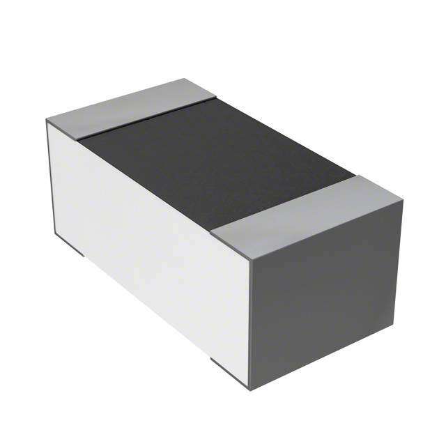
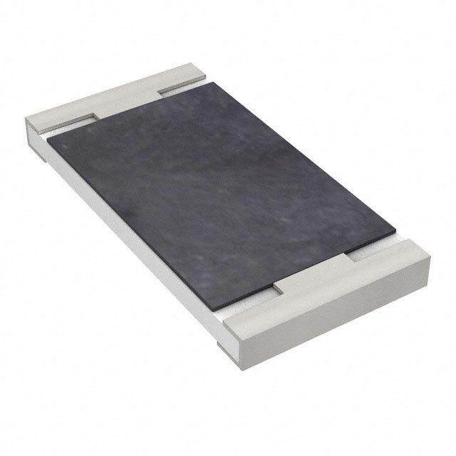
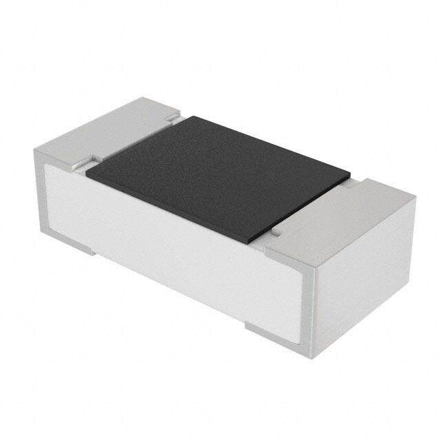
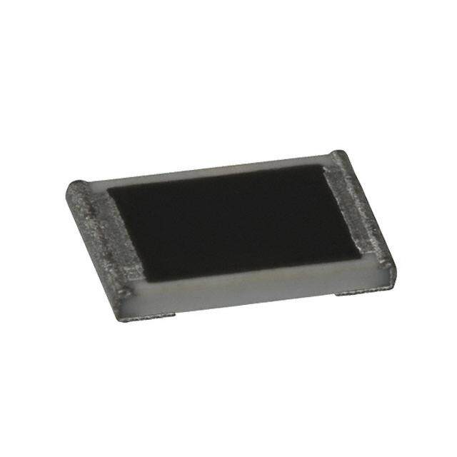
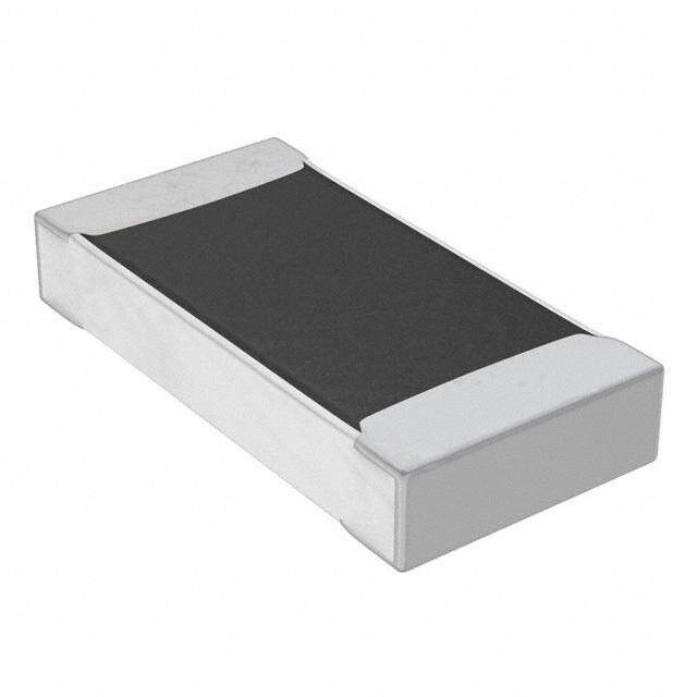
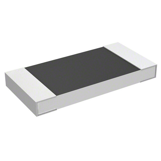
ICGOO电子元器件商城为您提供PR2512FKG070R001L由YAGEO AMERICA CORPORATION设计生产,在icgoo商城现货销售,并且可以通过原厂、代理商等渠道进行代购。 PR2512FKG070R001L价格参考。YAGEO AMERICA CORPORATIONPR2512FKG070R001L封装/规格:芯片电阻 - 表面安装, 1 mOhms ±1% 1W 金属元素 芯片电阻 2512(6432 公制) 电流检测 金属元素。您可以下载PR2512FKG070R001L参考资料、Datasheet数据手册功能说明书,资料中有PR2512FKG070R001L 详细功能的应用电路图电压和使用方法及教程。
Yageo品牌的芯片电阻型号PR2512FKG070R001L属于表面安装型电阻,广泛应用于电子电路中,主要起到限流、分压、偏置等作用。以下是该型号电阻的典型应用场景:

 1. 电源管理
   - 在电源模块中,用于限流或分压,确保电路稳定工作。
   - 可用作开关电源中的反馈网络电阻,调节输出电压。

 2. 信号处理
   - 在模拟信号和数字信号处理电路中,作为匹配电阻或负载电阻。
   - 用于滤波器设计,与电容配合构成低通、高通或带通滤波器。

 3. 传感器接口
   - 在传感器电路中,用于信号调理,例如温度、压力或光敏传感器的偏置或负载。
   - 提供稳定的参考电阻值,确保传感器输出信号的准确性。

 4. 通信设备
   - 在射频(RF)和无线通信电路中,用于阻抗匹配和信号衰减。
   - 应用于天线电路中,优化信号传输性能。

 5. 消费电子
   - 在音频设备中,用于音量控制、音效调整或信号放大电路。
   - 在显示器驱动电路中,用于电流限制或电压调节。

 6. 汽车电子
   - 用于车载电子系统中的信号隔离、保护及调节。
   - 在汽车照明电路中,作为电流限制电阻,保护LED灯或其他光源。

 7. 工业控制
   - 在电机驱动电路中,用于电流检测或速度控制。
   - 作为保护电阻,防止电路过载或短路。

 特性优势
- 小尺寸:适合高密度贴片组装,节省空间。
- 高精度:阻值为70Ω,公差小,适用于对精度要求较高的场景。
- 良好稳定性:温度系数低,能在宽温范围内保持性能稳定。
- 耐高温:适用于恶劣环境下的电子设备。

总之,PR2512FKG070R001L凭借其优异的性能和可靠性,适用于多种电子设备和复杂环境下的电路设计。
| 参数 | 数值 |
| 产品目录 | |
| 描述 | RES 0.001 OHM 1W 1% 2512 SMD |
| 产品分类 | |
| 品牌 | Yageo |
| 数据手册 | |
| 产品图片 |
|
| 产品型号 | PR2512FKG070R001L |
| rohs | 无铅 / 符合限制有害物质指令(RoHS)规范要求 |
| 产品系列 | PR |
| 产品目录绘图 |
|
| 产品目录页面 | |
| 供应商器件封装 | 2512 |
| 其它名称 | 311-0.001AGDKR |
| 功率(W) | 1W |
| 包装 | Digi-Reel® |
| 大小/尺寸 | 0.252" 长 x 0.126" 宽(6.40mm x 3.20mm) |
| 容差 | ±1% |
| 封装/外壳 | 2512(6432 公制) |
| 工作温度 | -55°C ~ 170°C |
| 成分 | 厚膜 |
| 标准包装 | 1 |
| 温度系数 | ±200ppm/°C |
| 特性 | 电流检测 |
| 特色产品 | http://www.digikey.com/cn/zh/ph/Yageo/PR2512.htmlhttp://www.digikey.cn/product-highlights/zh/currentsensing-chip-resistors/52488 |
| 电阻(Ω) | 0.001 |
| 端子数 | 2 |
| 高度 | 0.035"(0.90mm) |
-Series.jpg)


- 商务部:美国ITC正式对集成电路等产品启动337调查
- 曝三星4nm工艺存在良率问题 高通将骁龙8 Gen1或转产台积电
- 太阳诱电将投资9.5亿元在常州建新厂生产MLCC 预计2023年完工
- 英特尔发布欧洲新工厂建设计划 深化IDM 2.0 战略
- 台积电先进制程称霸业界 有大客户加持明年业绩稳了
- 达到5530亿美元!SIA预计今年全球半导体销售额将创下新高
- 英特尔拟将自动驾驶子公司Mobileye上市 估值或超500亿美元
- 三星加码芯片和SET,合并消费电子和移动部门,撤换高东真等 CEO
- 三星电子宣布重大人事变动 还合并消费电子和移动部门
- 海关总署:前11个月进口集成电路产品价值2.52万亿元 增长14.8%


PDF Datasheet 数据手册内容提取
DATA SHEET CURRENT SENSOR - LOW TCR PR series 5%, 1% sizes 0805/1206/2010/2512 RoHS compliant & Halogen free 0 V. 4 1 0 2 2, 2 t s u g u A – n o ti a c cifi e p s t c u d o r P
Product specification 2 Chip Resistor Surface Mount PR SERIES 0805/1206/2010/ 2512 11 SCOPE ORDERING INFORMATION - GLOBAL PART NUMBER This specification describes PR Global part numbers are identified by the series, size, tolerance, packing series current sensor - low TCR type, temperature coefficient, taping reel and resistance value. with lead-free terminations made by G LOBAL PART NUMBER metal substra te. PR XXXX X X X XX XXXX Z (1) (2) (3) (4) (5) (6) (7) APPLICATIONS (1) SIZE Consumer goods 0805/1206 / 2010 / 2512 Computer (2) TOLERANCE Telecom / Datacom F = ±1% Industrial / Power supply J = ±5% Alternative Energy (3) PACKAGING TYPE R = Paper taping reel FEATURES K = Embossed taping reel Halogen-free Epoxy (4) TEMPERATURE COEFFICIENT OF RESISTANCE RoHS compliant D = ±25 ppm/°C Reduce environmentally E = ±50 ppm/°C hazardous wastes F = ±100ppm/℃ High component and equipment reliability (5) TAPING REEL Non-forbidden materials used 07 / 7W / 7T / 47 = 7 inch dia. Reel and specific rated power in products/production Detailed power rating are shown in the Table 2. Low resistances applied to (6) RESISTANCE VALUE current sensing 0.5 mΩ to 100 mΩ There are 3~5 digits indicated the resistance value. Detailed coding rules of resistance are shown in the table of “Resistance rule of global part number”. (7) DEFAULT CODE Letter Z is the system default code for ordering only. (Note) Resistance rule of global part ORDERING EXAMPLE number The ordering code of a PR1206 1/4W Resistance code rule Examp le chip resistor, TC50, value 0.003Ω with ± 0U5 = 0.5 mΩ 1% tolerance, supplied in 7-inch tape reel is: PR1206FKE070R003Z 0RXXX 0R001 = 1 mΩ (0.5 to 100 mΩ) 0R1 = 100 mΩ NOTE 1. All our RChip products are RoHS compliant. "LFP" of the internal 2D reel label mentions "Lead-Free Process" www.yageo.com Aug. 22, 2014 V.0
Product specification 3 Chip Resistor Surface Mount PR SERIES 0805/1206/2010/ 2512 11 MARKING PR0805 No marking Fig. 1 P R1 206 / PR2010 / PR2512 4 digits The “R” is used as a decimal point; the other 3 digits are significant PR1206: 1mΩ to 50mΩ Fig. 2 Value = 3 mΩ PR2010: 4mΩ to 100mΩ PR2512: 5mΩ to 100mΩ PR2 010 / PR2512 4 digits The “R” is used as a decimal point; the other 3 digits are significant PR2010: 1 mΩ to 3 mΩ PR2512: 1 mΩ to 4 mΩ Fig. 3 Value = 1 mΩ PR2 512 4 digits The “m” is used as a decimal point; the other 3 digits are significant and the unit is milliohm PF series Note: construction will be PR2512: 0.5 mΩ to 2.5 mΩ adjusted to resistance value F ig. 4 Value = 0.5 mΩ (only for PF series). CO N STRUCTION Th e resistors are constructed using outstanding TCR level material, which makes Yageo PR resistors excellent for current sensing application in battery charger circuit & DC-DC converter. The composition of the resistive material is adjusted to give the approximate required resistance and is covered with a protective coating. Marking is printed on the top side of the resistor. Finally, the three external terminations (Cu / Ni / matte Tin) are added, as shown in Fig. 5. www.yageo.com Aug. 22, 2014 V.0
Product specification 4 Chip Resistor Surface Mount PR SERIES 0805/1206/2010/ 2512 11 OOuuttlliinneess For dimensions, p lease refer to Table 1 Fig. 5 PR1206~PR2512 Chip resistor outlines Fig. 5-1 PR0805 Chip resistor outlines D IM ENSION Table 1 For outlines, please refer to Fig. 5 TYP E RESISTANCE RANGE POWER RATING L (mm) W (mm) H (mm) I1 (mm) I2 (mm) PR0805 3mΩ≦ R≦ 50mΩ 1/8W, 1/4W, 1/2W 2.03±0.25 1.27±0.25 0.30±0.25 0.35±0.25 --- 1mΩ 3.20±0.25 1.60±0.25 0.64±0.25 0.50±0.25 0.50±0.25 2mΩ≦ R≦ 4mΩ 3.20±0.25 1.60±0.25 0.55±0.25 0.50±0.25 0.50±0.25 PR1206 1/4W, 1/2W, 1W 5mΩ 3.20±0.25 1.60±0.25 0.55±0.25 0.60±0.25 0.60±0.25 6mΩ≦ R≦ 50mΩ 3.20±0.25 1.60±0.25 0.55±0.25 0.50±0.25 0.50±0.25 1mΩ≦ R≦ 3mΩ 5.08±0.25 2.54±0.25 0.78±0.25 1.30±0.25 1.30±0.25 PR2010 3mΩ< R ≦ 4mΩ 1/2W, 1W 5.08±0.25 2.54±0.25 0.64±0.25 0.78±0.25 0.78±0.25 4mΩ< R ≦ 100mΩ 5.08±0.25 2.54±0.25 0.64±0.25 0.78±0.25 0.78±0.25 0.5mΩ≦ R≦ 3mΩ 6.25±0.25 3.20±0.25 0.78±0.25 1.88±0.25 1.88±0.25 3mΩ< R ≦ 4mΩ 6.25±0.25 3.20±0.25 0.78±0.25 1.88±0.25 1.88±0.25 1W 4mΩ< R ≦ 75mΩ 6.25±0.25 3.20±0.25 0.64±0.25 1.11±0.25 1.11±0.25 75mΩ< R ≦ 100mΩ 6.25±0.25 3.20±0.25 0.64±0.25 0.86±0.25 0.86±0.25 0.5mΩ≦ R ≦ 3mΩ 6.25±0.25 3.20±0.25 0.78±0.25 1.88±0.25 1.88±0.25 PR22512 3mΩ< R ≦ 4mΩ 2W 6.25±0.25 3.20±0.25 0.78±0.25 1.88±0.25 1.88±0.25 4mΩ< R ≦ 75mΩ 6.25±0.25 3.20±0.25 0.64±0.25 1.11±0.25 1.11±0.25 0.5mΩ 6.25±0.25 3.20±0.25 0.78±0.25 1.88±0.25 1.88±0.25 0.5mΩ< R ≦ 3mΩ 6.25±0.25 3.20±0.25 0.78±0.25 1.11±0.25 1.11±0.25 3W 3mΩ≦ R ≦ 4mΩ 6.25±0.25 3.20±0.25 0.78±0.25 1.67±0.25 1.67±0.25 4mΩ< R ≦ 10mΩ 6.25±0.25 3.20±0.25 0.64±0.25 1.11±0.25 1.11±0.25 Note: 1. For relevant physical dimensions, please refer to construction outlines. 2. Please contact with sales offices, distributors and representatives in your region before ordering. www.yageo.com Aug. 22, 2014 V.0
Product specification 5 Chip Resistor Surface Mount PR SERIES 0805/1206/2010/ 2512 11 ELECTRICAL CHARACTERISTICS Table 2 SERIES SIZE POWER RATING (1) TOLERANCE RESISTANCE RANGE TEMPERATURE COEFFICIENT OF RESISTANCE 07 7W 7T 47 3mΩ≦ R<5mΩ ± 100ppm/℃ 0805 1/8W 1/4W 1/2W 1W 3mΩ≦ R ≦ 50mΩ 5mΩ≦ R≦ 50mΩ ±50ppm/℃ Fig. 4 Chip resistor outlines 1206 1/4W 1/2W --- 1W ±1% 1 mΩ≦ R ≦ 50 mΩ PR ±50 ppm/°C 2010 1/2W 1W --- --- ±5% 1 mΩ ≦ R ≦ 100 mΩ 0.5mΩ ≦ R ≦ 3mΩ ±50 ppm/°C 2512 1W 2W 3W --- 0.5 mΩ ≦ R ≦ 100 mΩ 3mΩ< R ≦ 100mΩ ±25 ppm/°C Note: 1. Please contact with sales offices, distributors and representatives in your region before ordering. FUNCTIONAL DESCRIPTION OOPPEERRAATTIINNGG TTEEMMPPEERRAATTUURREE RRAANNGGEE PR0805 Range: -55℃ to + 150℃ PR1206~PR2512 Range: -55℃ to + 170℃ PPOOWWEERR RRAATTIINNGG Standard rated power at 70°C: PR0805: 1/8W PR1206: 1/4W PR2010: 1/2W Fig. 6 Maximum dissipation (Pm ax) in percentage of rated power PR2512: 1W as a function of the opera ting ambient temperature (T ) amb For detail power value, please refer to Table 2. RATED VOLTAGE The DC or AC (rms) continuous working voltage corresponding to the rated power is determined by the following formula: V = (PxR) Where V = Continuous rated DC or AC (rms) working voltage (V) P = Rated power (W) R = Resistance value (Ω) www.yageo.com Aug. 22, 2014 V.0
Product specification 6 Chip Resistor Surface Mount PR SERIES 0805/1206/2010/ 2512 11 PACKING STYLE AND PACKAGING QUANTITY Table 3 Pac king style and packaging quantity PACKING STYLE REEL DIMENSION PR0805 PR1206 PR2010 PR2512 Paper taping re el (R) 5,000 --- --- --- 7" (178 mm) Embossed taping reel (K) --- 4,000 2,000 4,000 EMBOSSED TAPE Fig. 7 Embossed Tape Ta ble 4 Dimensions of embossed tape for relevant chip resistors size SI ZE SYMBOL Unit: mm A0 B0 W E F P0 P1 P2 Ø D0 Ø D1 T PR0805 1.60±0.15 2.30±0.15 8.00±0.30 1.75±0.10 3.50±0.10 4.00±0.10 4.00±0.10 2.00±0.10 1.50±0.10 --- 0.40+0.20/-0 PR1206 1.83±0.10 3.50±0.10 8.00±0.15 1.75±0.10 3.50±0.10 4.00±0.10 4.00±0.10 2.00±0.10 1.55±0.05 1.00±0.10 0.90±0.10 PR2010 2.90±0.10 5.45±0.10 12.00±0.15 1.75±0.10 5.50±0.10 4.00±0.10 4.00±0.10 2.00±0.10 1.50±0.05 1.50±0.10 1.10±0.10 PR2512 3.90±0.10 6.74±0.10 12.00±0.15 1.75±0.10 5.50±0.10 4.00±0.10 4.00±0.10 2.00±0.10 1.55±0.05 1.50±0.10 1.08±0.10 www.yageo.com Aug. 22, 2014 V.0
Product specification 7 Chip Resistor Surface Mount PR SERIES 0805/1206/2010/ 2512 11 REEL SPECIFICATION Fig. 8 Reel Table 5 Dimensions of reel specification for relevant chip resistors size REEL SIZE SYMBOL Unit: mm QUANTITY SIZE PER REEL 8 mm 12 mm A N C D W W TAPE WIDE TAPE WIDE 1 2 MAX. 7" PR0805 5000 --- 178.0±1.0 60.0+1/-0 13.20±0.5 17.70±0.5 8.4 +1/-0 12.4±0.5 (Ø178 mm) 7" PR1206 4000 -- 178.0±1.0 60.0±0.5 13.20±0.5 17.70±0.5 9.0±0.3 12.0±0.5 (Ø178 mm) 7" PR2010 2000 -- 178.0±1.0 60.0±0.5 13.50±0.5 17.70±0.5 13.0±0.5 16.2±0.5 (Ø178 mm) 7" PR2512 4000 -- 178.0±1.0 60.0±0.5 13.50±0.5 17.70±0.5 13.0±0.5 16.2±0.5 (Ø178 mm) LEADER/TRAILER TAPE SPECIFICATION Fig. 9 Leader/Trailer Tape www.yageo.com Aug. 22, 2014 V.0
Product specification 8 Chip Resistor Surface Mount PR SERIES 0805/1206/2010/ 2512 11 FOOTPRINT AND SOLDERING PROFILES For recommended soldering profiles, please refer to data sheet “Chip resistors mounting”. FOOTPRINT Fig. 10 Single resistor chips recommended dimensions of footprints Table 6 Footprint dimensions Unit: mm RESISTANCE SIZE RANGE POWER RATING A B C D PR0805 3mΩ≦ R ≦50 mΩ 1/8W, 1/4W, 1/2W 4.26 0.66 1.80 2.18 PR1206 1mΩ ≦ R ≦ 50mΩ 1/4W, 1/2W, 1W 4.20 1.00 1.60 2.18 1mΩ ≦ R ≦ 3mΩ 7.00 1.22 2.89 2.92 PR2010 1/2W, 1W 3mΩ< R ≦100 mΩ 6.99 2.41 2.29 2.92 0.5mΩ ≦ R ≦ 4mΩ 7.37 1.27 3.05 3.68 1W, 2W 4mΩ< R ≦100 mΩ 7.40 3.18 2.11 3.68 0.5mΩ 7.37 1.27 3.05 3.68 PR2512 0.5mΩ < R < 3mΩ, 3W 7.38 3.00 2.19 3.68 4mΩ< R ≦10 mΩ 3mΩ ≦ R ≦ 4mΩ 7.38 1.80 2.79 3.68 www.yageo.com Aug. 22, 2014 V.0
Product specification 9 Chip Resistor Surface Mount PR SERIES 0805/1206/2010/ 2512 11 TESTS AND REQUIREMENTS Table 8 Test condition, procedure and requirements TEST TEST METHOD PROCEDURE REQUIREMENTS Life/ MIL-STD-202G-method 108A 1,000 hours at 70±5 °C applied RCWV ±(1%+0.0005 Ω) Operational Life/ IEC 60115-1 4.25.1 1.5 hours on, 0.5 hour off, still air required Endurance JIS C 5202-7.10 High MIL-STD-202G-method 108A 1,000 hours at maximum operating temperature ±(1%+0.0005 Ω) Temperature IEC 60115-1 4.25.3 depending on specification, unpowered Exposure/ JIS C 5202-7.11 No direct impingement of forced air to the parts Endurance at Tolerances: 170±3 °C Upper Category Temperature Moisture MIL-STD-202G-method 106F Each temperature / humidity cycle is defined at 8 ±(0.5%+0.0005 Ω) Resistance IEC 60115-1 4.24.2 hours (method 106F), 3 cycles / 24 hours for 10d with 25 °C / 65 °C 95% R.H, without steps 7a & 7b, unpowered Parts mounted on test-boards, without condensation on parts Measurement at 24±2 hours after test conclusion Thermal Shock MIL-STD-202G-method 107G PR1206~PR2512 : -55/+155 ℃ ±(0.5%+0.0005 Ω) PR0805 : -55/+125 ℃ Note: Number of cycles required is 300. Maximum transfer time is 20 seconds. Dwell time is 15 minutes. Air – Air Short Time MIL-R-55342D-para 4.7.5 5 times of rated power for 5 seconds at room ±(0.5%+0.0005 Ω) Overload IEC60115-1 4.13 temperature No visible damage Board Flex/ IEC60115-1 4.33 Device mounted on PCB test board as described, ±(1%+0.0005 Ω) Bending only 1 board bending required No visible damage Bending for 0805/1206/2010/2512: 2 mm Holding time: minimum 60 seconds Humidity IEC 60115-1 4.21 Steady state for 1000 hours at 40 °C / 95% R.H. ±(1%+0.0005Ω) RCWV applied for 1.5 hours on and 0.5 hour off www.yageo.com Aug. 22, 2014 V.0
Product specification 10 Chip Resistor Surface Mount PR SERIES 0805/1206/2010/ 2512 11 TEST TEST METHOD PROCEDURE REQUIREMENTS Solderability - Wetting IPC/JEDECJ-STD-002B test B Electrical Test not required Well tinned (≥95% covered) IEC 60068-2-58 Magnification 50X No visible damage SMD conditions: 1st step: method B, aging 4 hours at 155 °C dry heat 2nd step: leadfree solder bath at 245±3 °C Dipping time: 3±0.5 seconds - Leaching IPC/JEDECJ-STD-002B test D Leadfree solder, 260 °C, 30 seconds No visible damage IEC 60068-2-58 immersion time - Resistance to MIL-STD-202G-method 210F Condition B, no pre-heat of samples ±(0.5%+0.0005 Ω) Soldering Heat IEC 60068-2-58 Leadfree solder, 260 °C, 10 seconds No visible damage immersion time Procedure 2 for SMD: devices fluxed and cleaned with isopropanol www.yageo.com Aug. 22, 2014 V.0
Product specification 11 Chip Resistor Surface Mount PR SERIES 0805/1206/2010/ 2512 11 REVISION HISTORY REVISION DATE CHANGE NOTIFICATION DESCRIPTION TEMPERATURE COEFFICIENT Version 0T YPE Aug. 22, 2014 - POWER TOL-E NReAwN dCaEta sheeRt EfoSIrS cTuArrNenCt Ese RnsAoNr -G loEw TCR PR series sizes of OF RESISTANCE 0805/1206/2010/2512, 1% and 5% with lead-free terminations 0603 1/10W, 1/5W, 3/10W, 2/5W, 1/2W 5 mΩ≦ R < 100 mΩ 0805 1/8W, 1/4W, 1/3W, 1/2W 4 mΩ ≦ R < 100 mΩ 1206 1/4W, 1/2W 3 mΩ ≦ R < 100 mΩ 1/2W, 1W The resistors are constructed using outstanding TCR level material, which makes Yageo PF resistors excellent for current sensing application in battery charger circuit & DC-DC converter. The composition of the resistive ±1% PF 2010 material is adjusted to give the ±2% 5 mΩ ≦ R < 100 mΩ ±75 ppm/°C approximate required resistance ±5% and is covered with a protective coating, which printed with the resistance value. Finally, the three external terminations (Ni / matte Tin) are added, as shown in Fig. 4. 1W, 2W 1 mΩ ≦ R < 100 mΩ 2512 3W 1 mΩ ≦ R ≦ 50 mΩ 4527 2W, 3W, 5W 6 mΩ ≦ R < 1Ω NOTE: 1. PLEASE CONTACT WITH SALES OFFICES, DISTRIBUTORS AND REPRESENTATIVES IN YOUR REGION BEFORE ORDERING “ Yageo reserves all the rights for revising the content of this datasheet without further notification, as long as the products itself are unchanged. Any product change will be announced by PCN.” www.yageo.com Aug. 22, 2014 V.0