 Datasheet下载
- 型号: PME271Y422MR30
- 制造商: Kemet
- 库位|库存: xxxx|xxxx
- 要求:
| 数量阶梯 | 香港交货 | 国内含税 |
| +xxxx | $xxxx | ¥xxxx |
查看当月历史价格
查看今年历史价格
PME271Y422MR30产品简介:
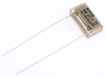
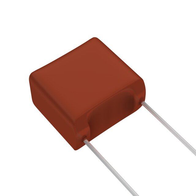
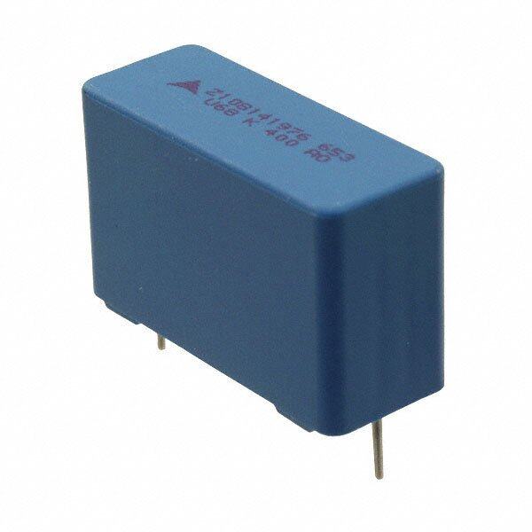
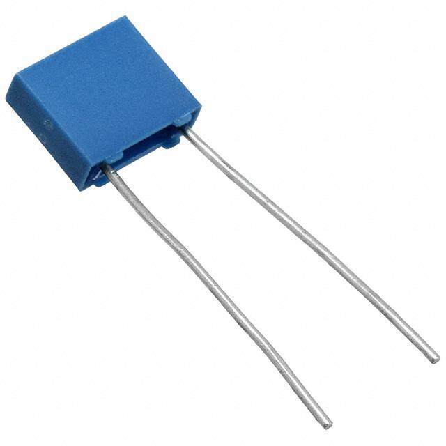
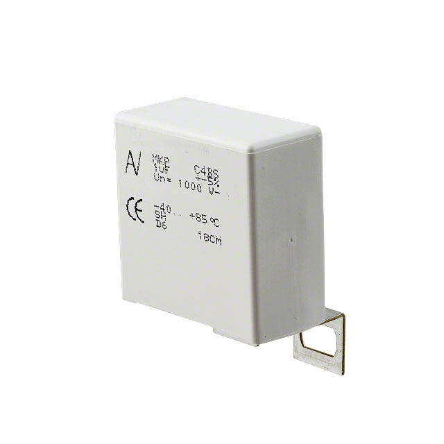
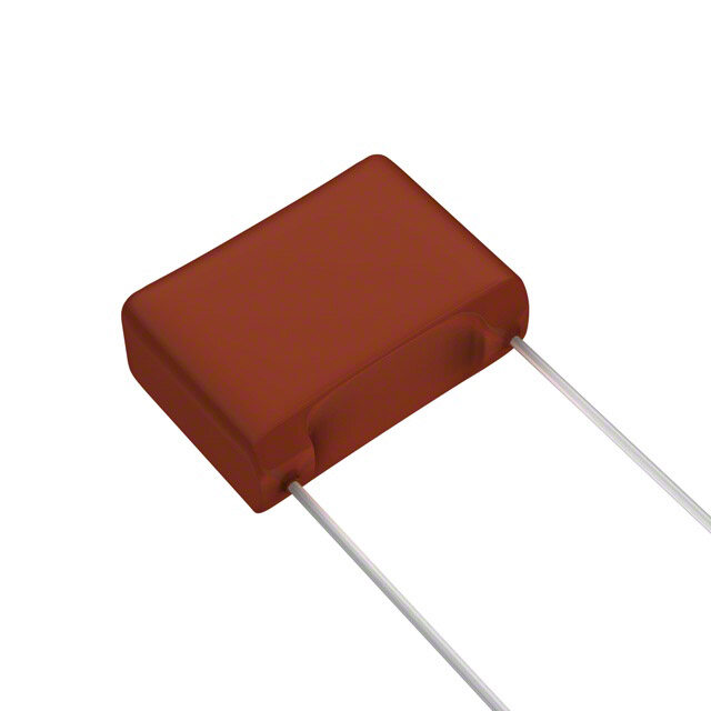
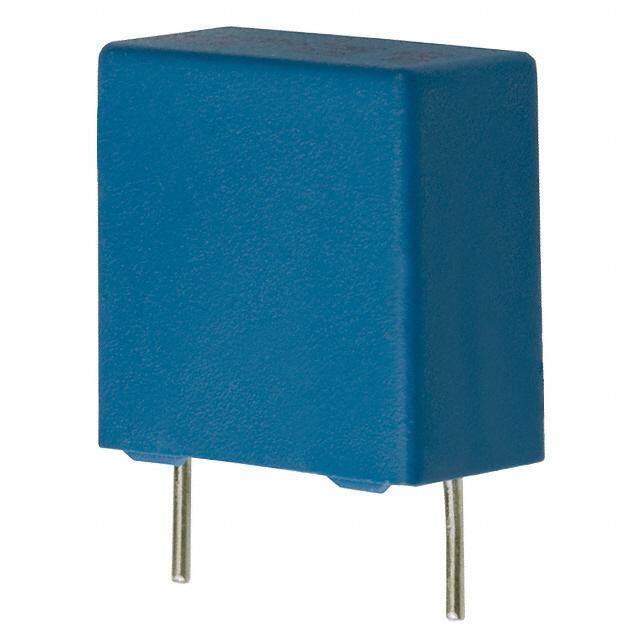
ICGOO电子元器件商城为您提供PME271Y422MR30由Kemet设计生产,在icgoo商城现货销售,并且可以通过原厂、代理商等渠道进行代购。 PME271Y422MR30价格参考¥2.36-¥2.36。KemetPME271Y422MR30封装/规格:薄膜电容器, 2200pF 薄膜电容器 250V 1000V(1kV) 纸,金属化 径向。您可以下载PME271Y422MR30参考资料、Datasheet数据手册功能说明书,资料中有PME271Y422MR30 详细功能的应用电路图电压和使用方法及教程。
KEMET的PME271Y422MR30是一款薄膜电容器,广泛应用于多种电子设备和系统中。该型号电容器的主要应用场景包括但不限于以下几个方面:

 1. 电源管理
   在电源管理系统中,PME271Y422MR30可以用于滤波、耦合和去耦等应用。它能够有效抑制电源中的噪声和纹波,确保电源输出的稳定性。特别是在开关电源(SMPS)中,该电容器可以与电感器和其他元件配合使用,提供高效的能量转换和稳定的电压输出。

 2. 音频设备
   在音频设备中,PME271Y422MR30常用于音频信号的耦合和旁路。由于其低损耗特性和高稳定性,它可以确保音频信号在传输过程中不失真,保持高质量的声音输出。此外,它还可以用于消除音频电路中的高频噪声,提升音质表现。

 3. 工业自动化
   在工业自动化领域,PME271Y422MR30可用于电机驱动器、逆变器和变频器等设备中。这些设备通常需要处理大电流和高频率信号,而该电容器的高耐压和低ESR(等效串联电阻)特性使其能够在这些严苛环境下稳定工作,确保系统的可靠性和效率。

 4. 汽车电子
   在汽车电子系统中,PME271Y422MR30可以用于车载充电器、LED照明、传感器接口等应用。它能够承受汽车环境中常见的温度变化和振动,提供稳定的电气性能。特别是在新能源汽车中,该电容器可用于电池管理系统(BMS)和逆变器中,确保电力系统的高效运行。

 5. 通信设备
   在通信设备中,PME271Y422MR30可用于射频(RF)电路中的滤波和匹配网络。它具有良好的高频特性,能够在高频段提供稳定的阻抗匹配,减少信号损失和干扰。此外,它还可以用于基站、路由器等设备中的电源滤波,确保通信信号的稳定传输。

 总结:
PME271Y422MR30凭借其优异的电气性能和可靠性,适用于多种应用场景,尤其是在对电容器性能要求较高的电源管理、音频设备、工业自动化、汽车电子和通信设备等领域中表现出色。
| 参数 | 数值 |
| 产品目录 | |
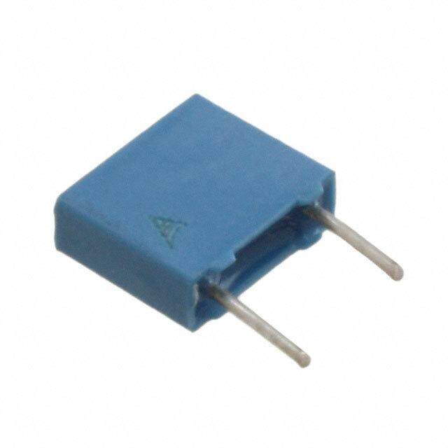
| 描述 | CAP FILM 2200PF 250VAC RADIAL薄膜电容器 250volts 2200pF 20% LS 10.2mm |
| ESR(等效串联电阻) | - |
| 产品分类 | |
| 品牌 | Kemet |
| 产品手册 | |
| 产品图片 |
|
| rohs | 符合RoHS无铅 / 符合限制有害物质指令(RoHS)规范要求 |
| 产品系列 | 薄膜电容器,Kemet PME271Y422MR30PME271Y |
| 数据手册 | http://capacitoredge.kemet.com/capedge2/DataSheet?pn=P271HE222M250A |
| 产品型号 | PME271Y422MR30 |
| 产品 | Safety Film Capacitors |
| 产品培训模块 | http://www.digikey.cn/PTM/IndividualPTM.page?site=cn&lang=zhs&ptm=25569 |
| 产品目录绘图 |
|
| 产品目录页面 | |
| 产品种类 | |
| 介电材料 | 纸,金属化 |
| 其它名称 | 399-5410 |
| 包装 | 散装 |
| 单位重量 | 700 mg |
| 商标 | Kemet |
| 外壳宽度 | 3.9 mm |
| 外壳长度 | 13.5 mm |
| 外壳高度 | 7.5 mm |
| 大小/尺寸 | 0.532" 长 x 0.154" 宽(13.50mm x 3.90mm) |
| 安装类型 | 通孔 |
| 容差 | ±20% |
| 封装 | Bulk |
| 封装/外壳 | 径向 |
| 工作温度 | -40°C ~ 100°C |
| 工厂包装数量 | 1000 |
| 应用 | EMI、RFI 抑制 |
| 引线类型 | Straight |
| 引线间距 | 0.402"(10.20mm) |
| 引线间隔 | 10.2 mm |
| 损耗因数DF | |
| 标准包装 | 1,000 |
| 特性 | 达到 Y2 安全等级 |
| 电介质 | Paper |
| 电压额定值AC | 300 V |
| 电压额定值DC | 1 kV |
| 电容 | 2200pF |
| 端接 | PC 引脚 |
| 端接类型 | Radial |
| 类 | Y2 |
| 类型 | General Purpose AC / DC Metallized Paper Capacitor |
| 系列 | PME271Y |
| 零件号别名 | P271HE222M250A |
| 额定电压-AC | 250V |
| 额定电压-DC | - |
| 高度-安装(最大值) | 0.295"(7.50mm) |


- 商务部:美国ITC正式对集成电路等产品启动337调查
- 曝三星4nm工艺存在良率问题 高通将骁龙8 Gen1或转产台积电
- 太阳诱电将投资9.5亿元在常州建新厂生产MLCC 预计2023年完工
- 英特尔发布欧洲新工厂建设计划 深化IDM 2.0 战略
- 台积电先进制程称霸业界 有大客户加持明年业绩稳了
- 达到5530亿美元!SIA预计今年全球半导体销售额将创下新高
- 英特尔拟将自动驾驶子公司Mobileye上市 估值或超500亿美元
- 三星加码芯片和SET,合并消费电子和移动部门,撤换高东真等 CEO
- 三星电子宣布重大人事变动 还合并消费电子和移动部门
- 海关总署:前11个月进口集成电路产品价值2.52万亿元 增长14.8%

PDF Datasheet 数据手册内容提取
AC Line EMI Suppression and RC Networks PME271Y, Metallized Impregnated Paper, Class Y2, 250 VAC Overview Applications Multilayer, metallized paper, encapsulated and impregnated For worldwide use as an electromagnetic interference in self-extinguishing material that meets the requirements of suppressor in all Y2 applications, line-to-earth. UL 94 V–0. Benefits • Approvals: ENEC, UL, cUL, CQC • Rated voltage: 250 VAC 50/60 Hz • Capacitance range: 0.001 – 0.1 µF • Lead spacing: 10.2 – 25.4 mm • Capacitance tolerance: ±20% • Climatic category: 40/100/56/B, IEC 60068–1 • Tape & Reel packaging in accordance with IEC 60286–2 • RoHS compliance and lead-free terminations • Operating temperature range of −40°C to +100°C • 100% screening factory test at 3,000 VDC • Highest possible safety regarding active and passive flammability Customer Part Number System PME271 Y 410 M R30 Capacitance Series Rated Voltage (VAC) Capacitance Code (pF) Packaging Tolerance Y2, Metallized Paper Y = 250 The last two digits M = ±20% See Ordering represent significant Options Table figures. The first digit specifies the total number of digits. KEMET Internal Part Number System P 271 H E 102 M 250 A Lead Spacing Capacitance Capacitance Rated Voltage Lead and Capacitor Class Series Size Code (mm) Code (pF) Tolerance (VAC) Packaging Code P = Paper Y2, Metallized H = 10.2 See Dimension First two digits M = ±20% 250 = 250 See Ordering Paper Q = 15.2 Table represent Options Table C = 20.3 significant E = 25.4 figures. Third digit specifies number of zeros. One world. One KEMET © KEMET Electronics Corporation • KEMET Tower • One East Broward Boulevard F3016_PME271Y_Y2_250 • 8/23/2019 1 Fort Lauderdale, FL 33301 USA • 954-766-2800 • www.kemet.com
Film Capacitors – AC Line EMI Suppression and RC Networks PME271Y, Metallized Impregnated Paper, Class Y2, 250 VAC Benefits cont. • Excellent self-healing properties ensure long life, even • Impregnated paper that ensures excellent stability and when subjected to frequent overvoltages reliability, particularly in applications with continuous • Good resistance to ionization due to impregnated dielectric operation • High dv/dt capability Ordering Options Table Lead KEMET Legacy Spacing Lead Length Lead and Lead and Type of Leads and Packaging Nominal (mm) Packaging Packaging (mm) Code Code Standard Lead and Packaging Options Bulk (Bag) – Short Leads 6 +0/−1 C R06 Bulk (Bag) – Maximum Length Leads 30 +5/−0 A R30 10.2 Tape & Reel (Standard Reel) H= 18.5 ±0.5 L R19T0 0 Other Lead and Packaging Options Tape & Reel (Large Reel) H= 18.5 ±0.5 P R19T1 0 Native 10.2 Ammo Pack H= 18.5 ±0.5 LAF3 R30XA formed to 7.5 0 Standard Lead and Packaging Options Bulk (Bag) – Short Leads 6 +0/−1 C R06 Bulk (Bag) – Maximum Length Leads 30 +5/−0 A R30 15.2 Tape & Reel (Standard Reel) H= 18.5 ±0.5 L R19T0 0 Other Lead and Packaging Options Tape & Reel (Large Reel) H= 18.5 ±0.5 P R19T1 0 Standard Lead and Packaging Options Bulk (Bag) – Short Leads 6 +0/−1 C R06 Bulk (Bag) – Maximum Length Leads 30 +5/−0 A R30 20.3 Tape & Reel (Standard Reel) H= 18.5 ±0.5 L R19T0 0 Other Lead and Packaging Options Tape & Reel (Large Reel) H= 18.5 ±0.5 P R19T1 0 Standard Lead and Packaging Options 25.4 Bulk (Bag) – Short Leads 6 +0/−1 C R06 Bulk (Bag) – Maximum Length Leads 30 +5/−0 A R30 © KEMET Electronics Corporation • KEMET Tower • One East Broward Boulevard F3016_PME271Y_Y2_250 • 8/23/2019 2 Fort Lauderdale, FL 33301 USA • 954-766-2800 • www.kemet.com
Film Capacitors – AC Line EMI Suppression and RC Networks PME271Y, Metallized Impregnated Paper, Class Y2, 250 VAC Dimensions – Millimeters FRONT VIEW SIDE VIEW L B H d LL p p B H L d Nominal Tolerance Nominal Tolerance Nominal Tolerance Nominal Tolerance Nominal Tolerance 10.2 ±0.4 3.9 Maximum 7.5 Maximum 13.5 Maximum 0.6 ±0.05 10.2 ±0.4 4.1 Maximum 8.2 Maximum 13.5 Maximum 0.6 ±0.05 10.2 ±0.4 5.1 Maximum 10.5 Maximum 13.5 Maximum 0.6 ±0.05 15.2 ±0.4 5.2 Maximum 10.5 Maximum 18.5 Maximum 0.8 ±0.05 15.2 ±0.4 5.5 Maximum 11.0 Maximum 18.5 Maximum 0.8 ±0.05 15.2 ±0.4 7.3 Maximum 13.0 Maximum 18.5 Maximum 0.8 ±0.05 20.3 ±0.4 7.6 Maximum 14.0 Maximum 24.0 Maximum 0.8 ±0.05 20.3 ±0.4 9.0 Maximum 15.0 Maximum 24.0 Maximum 0.8 ±0.05 20.3 ±0.4 11.3 Maximum 16.5 Maximum 24.0 Maximum 0.8 ±0.05 25.4 ±0.4 12.1 Maximum 19.0 Maximum 30.5 Maximum 1.0 ±0.05 Note: See the Ordering Options Table for lead length (LL) options. © KEMET Electronics Corporation • KEMET Tower • One East Broward Boulevard F3016_PME271Y_Y2_250 • 8/23/2019 3 Fort Lauderdale, FL 33301 USA • 954-766-2800 • www.kemet.com
Film Capacitors – AC Line EMI Suppression and RC Networks PME271Y, Metallized Impregnated Paper, Class Y2, 250 VAC Performance Characteristics Rated Voltage 250 VAC 50/60 Hz Capacitance Range 0.001 – 0.1 µF Capacitance Tolerance ±20% Temperature Range −40°C to +100°C Climatic Category 40/100/56/B Approvals ENEC, UL, CSA, CQC Maximum Values at +23°C Dissipation Factor 1 kHz 1.3% The 100% screening factory test is carried out at 3,000 VDC. The voltage level is selected to meet the requirements in applicable equipment standards. All Test Voltage Between Terminals electrical characteristics are checked after the test. This test may not be repeated due to potential capacitor damage. KEMET is not liable for any failures that result from repeating the test. Minimum Value Between Terminals Insulation Resistance 12,000 MΩ In DC Applications Recommended voltage ≤ 1,000 VDC Environmental Test Data Test IEC Publication Procedure Vibration IEC 60068–2–6 Test Fc 3 directions at 2 hours each 10 – 500 Hz at 0.75 mm or 98 m/s2 Bump IEC 60068–2–29 Test Eb 4,000 bumps at 390 m/s2 Solderability IEC 60068–2–20 Test Ta Solder globule method Active flammability IEC 60384–14 Passive flammability IEC 60384–14 Needle-flame test Humidity IEC 60068–2–3 Test Ca +40°C and 90 – 95% R.H. © KEMET Electronics Corporation • KEMET Tower • One East Broward Boulevard F3016_PME271Y_Y2_250 • 8/23/2019 4 Fort Lauderdale, FL 33301 USA • 954-766-2800 • www.kemet.com
Film Capacitors – AC Line EMI Suppression and RC Networks PME271Y, Metallized Impregnated Paper, Class Y2, 250 VAC Approvals Mark Specification File Number EN/IEC 60384–14 SE/0140–27D UL 60384–14 E73869 CAN/CSA–E60384–14–09 CQC 14001107140 Environmental Compliance All KEMET EMI capacitors are RoHS compliant. Table 1 – Ratings & Part Number Reference Maximum Dimensions in Capacitance Lead f dV/dt KEMET Internal Customer mm o Value (µF) Spacing (p) (MHz) (V/µs) Part Number Part Number B H L 0.0010 3.9 7.5 13.5 10.2 53 2,000 P271HE102M250(1) PME271Y410M(1) 0.0015 3.9 7.5 13.5 10.2 44 2,000 P271HE152M250(1) PME271Y415M(1) 0.0022 3.9 7.5 13.5 10.2 37 2,000 P271HE222M250(1) PME271Y422M(1) 0.0033 4.1 8.2 13.5 10.2 30 2,000 P271HH332M250(1) PME271Y433M(1) 0.0047 5.1 10.5 13.5 10.2 24 2,000 P271HL472M250(1) PME271Y447M(1) 0.0068 5.2 10.5 18.5 15.2 19 1,400 P271QE682M250(1) PME271Y468M(1) 0.0100 5.2 10.5 18.5 15.2 16 1,400 P271QE103M250(1) PME271Y510M(1) 0.0150 5.5 11.0 18.5 15.2 13 1,400 P271QH153M250(1) PME271Y515M(1) 0.0220 7.3 13.0 18.5 15.2 9.8 1,400 P271QM223M250(1) PME271Y522M(1) 0.0330 7.6 14.0 24.0 20.3 7.0 1,000 P271CE333M250(1) PME271Y533M(1) 0.0470 9.0 15.0 24.0 20.3 6.0 1,000 P271CJ473M250(1) PME271Y547M(1) 0.0680 11.3 16.5 24.0 20.3 4.6 600 P271CP683M250(1) PME271Y568M(1) 0.1000 12.1 19.0 30.5 25.4 3.9 400 P271EJ104M250(1) PME271Y610M(1) Capacitance Lead Spacing dV/dt KEMET Internal Customer B (mm) H (mm) L (mm) f (MHz) Value (µF) (p) o (V/µs) Part Number Part Number (1) Insert ordering code for lead type and packaging. See Ordering Options Table for available options. © KEMET Electronics Corporation • KEMET Tower • One East Broward Boulevard F3016_PME271Y_Y2_250 • 8/23/2019 5 Fort Lauderdale, FL 33301 USA • 954-766-2800 • www.kemet.com
Film Capacitors – AC Line EMI Suppression and RC Networks PME271Y, Metallized Impregnated Paper, Class Y2, 250 VAC Soldering Process The implementation of the RoHS directive has resulted in the selection of SnAuCu (SAC) alloys or SnCu alloys as a primary solder. This has increased the liquidus temperature from 183°C for SnPb eutectic alloy to 217 – 221°C for the new alloys. As a result, the heat stress to the components, even in wave soldering, has increased considerably due to higher pre-heat and wave temperatures. Polypropylene capacitors are especially sensitive to heat (the melting point of polypropylene is 160 – 170°C). Wave soldering can be destructive, especially for mechanically small polypropylene capacitors (with lead spacing of 5 – 15 mm). Great care must be taken during soldering. The recommended solder profiles from KEMET should be used. Consult KEMET with any questions. In general, the wave soldering curve from IEC Publication 61760-1 Edition 2 serves as a solid guideline for successful soldering. See Figure 1. Reflow soldering is not recommended for through-hole film capacitors. Exposing capacitors to a soldering profile in excess of the recommended limits may result in degradation or permanent damage to the capacitors. Do not place the polypropylene capacitor through an adhesive curing oven to cure resin for surface-mount components. Insert through-hole parts after curing the surface mount parts. Consult KEMET to discuss the actual temperature profile in the oven, if through-hole components must pass through the adhesive curing process. A maximum of two soldering cycles is recommended. Allow time for the capacitor surface temperature to return to a normal temperature before the second soldering cycle. Manual Soldering Recommendations Wave Soldering Recommendations 300 Following is the recommendation for manual 2 +3 seconds maximum 260°C soldering with a soldering iron. 250 First Wave Second Wave 200 Recommended Soldering Temperature C) ∆T < 150°C Cooling mperature (°C)233450500000 Temperature (° 11505000 PreThpreehaetai1tn1g5° cccaaa 235.°°5CC°//Css/eescceoocnnoddnd typical Soldering Iron Bit Te112050000 00 40 80 T12im0e (s) 160 200 240 50 0 0 1 2 3 4 5 6 7 8 Soldering Time (seconds) Soldering iron tip temperature should be set at 350°C (+10°C maximum), with the soldering duration not to exceed more than 3 seconds. © KEMET Electronics Corporation • KEMET Tower • One East Broward Boulevard F3016_PME271Y_Y2_250 • 8/23/2019 6 Fort Lauderdale, FL 33301 USA • 954-766-2800 • www.kemet.com
Film Capacitors – AC Line EMI Suppression and RC Networks PME271Y, Metallized Impregnated Paper, Class Y2, 250 VAC Soldering Process cont. Wave Soldering Recommendations cont'd 1. The table indicates the maximum setup temperature for the soldering process. Maximum Peak Soldering Maximum Preheat Temperature Dielectric Temperature film material Capacitor Capacitor Capacitor Capacitor Capacitor Pitch ≤ 10 mm Pitch = 15 mm Pitch > 15 mm Pitch ≤ 15 mm Pitch > 15 mm Polyester 130°C 130°C 130°C 270°C 270°C Polypropylene 100°C 110°C 130°C 260°C 270°C Paper 130°C 130°C 140°C 270°C 270°C Polyphenylene 150°C 150°C 160°C 270°C 270°C Sulphide 2. The maximum temperature measured inside the capacitor: set the temperature so that inside the element the maximum temperature is below the limit. Maximum Temperature Dielectric Film Material Measured Inside the Element Polyester 160°C Polypropylene 110°C Paper 160°C Polyphenylene Sulphide 160°C Temperature monitored inside the capacitor. Selective Soldering Recommendations Selective dip soldering is a variation of reflow soldering. In this method, the printed circuit board with through-hole components to be soldered is preheated and transported over the solder bath, as in normal flow soldering, without touching the solder. When the board is over the bath, it is stopped. Pre-designed solder pots are lifted from the bath with molten solder, only at the places of the selected components, and pressed against the lower surface of the board to solder the components. The temperature profile for selective soldering is similar to the double wave flow soldering outlined in this document. However, instead of two baths, there is only one with a time from 3 to 10 seconds. In selective soldering, the risk of overheating is greater than in double wave flow soldering. Great care must be taken so that the parts do not overheat. © KEMET Electronics Corporation • KEMET Tower • One East Broward Boulevard F3016_PME271Y_Y2_250 • 8/23/2019 7 Fort Lauderdale, FL 33301 USA • 954-766-2800 • www.kemet.com
Film Capacitors – AC Line EMI Suppression and RC Networks PME271Y, Metallized Impregnated Paper, Class Y2, 250 VAC Construction Detailed Cross Section Self-Extinguishing Metallized Impregnated Paper Resin Self-Extinguishing (First Layer) Resin Metallized Impregnated Paper (Second Layer) Margin Margin Metal Contact Layer Margin Leads Metal Contact Layer Winding Scheme Metallization Metal Spraying Material Impregnated Paper Single Design — Multilayer Impregnated Paper Dielectric 1 Section © KEMET Electronics Corporation • KEMET Tower • One East Broward Boulevard F3016_PME271Y_Y2_250 • 8/23/2019 8 Fort Lauderdale, FL 33301 USA • 954-766-2800 • www.kemet.com
Film Capacitors – AC Line EMI Suppression and RC Networks PME271Y, Metallized Impregnated Paper, Class Y2, 250 VAC Marking FRONT BACK Voltage Self Healing Series Approval Approval Mark Mark IEC Climatic Category Manufacturing Date Code TOP Capacitance Safety Class Packaging Quantities Lead Spacing Thickness Height Length Bulk Bulk Standard Reel Large Reel Ammo (mm) (mm) (mm) (mm) Short Leads Long Leads 360 mm 500 mm Formed 3.9 7.5 13.5 2,000 1,000 700 1,400 800 10.2 4.1 8.2 13.5 2,000 1,000 600 780 5.1 10.5 13.5 1,600 800 600 1,200 630 5.5 12.5 18.0 1,000 500 600 6.5 12.5 18.0 600 400 400 7.5 14.5 18.0 600 400 400 8.5 16.0 18.0 400 250 400 5.2 10.5 18.5 1,000 500 600 15.2 5.5 11.0 18.5 1,000 500 500 6.0 12.5 18.5 600 400 400 7.3 13.0 18.5 600 400 400 800 7.8 13.5 18.5 600 400 400 8.5 14.3 18.5 500 300 350 7.6 14.0 24.0 1,500 250 250 500 8.4 14.0 24.0 1,200 200 250 500 20.3 9.0 15.0 24.0 1,500 200 250 11.3 16.5 24.0 1,000 150 180 400 10.6 16.1 30.5 1,000 150 10.5 17.3 30.5 1,000 100 25.4 12.1 19.0 30.5 800 100 15.3 22.0 30.5 600 75 © KEMET Electronics Corporation • KEMET Tower • One East Broward Boulevard F3016_PME271Y_Y2_250 • 8/23/2019 9 Fort Lauderdale, FL 33301 USA • 954-766-2800 • www.kemet.com
Film Capacitors – AC Line EMI Suppression and RC Networks PME271Y, Metallized Impregnated Paper, Class Y2, 250 VAC Lead Taping & Packaging (IEC 60286–2) Lead Spacing 10.2 – 15.2 mm Lead Spacing 20.3 – 22.5 mm ∆p ∆p ∆p ∆p ∆h ∆h ∆h ∆h W H1 F W2 H1 F W2 H0 W0 W1 H0 W0 W1 W W P P D P P D D 1 0 0 0 1 0 0 t t Formed Leads from 10.2 – 7.5 mm ∆p ∆p ∆h ∆h H1 W2 W0 W1 F = 7.5 H 0 W P P D 0 1 0 Taping Specification Dimensions in mm Standard IEC 60286–2 Lead Spacing +6/−0.1 F Formed 7.5 10.2 15.2 20.3 22.5 F Carrier Tape Width ±0.5 W 18 18 18 18 18 18 +1/−0.5 Hold-Down Tape Width Minimum W 5 5 5 5 5 0 Position of Sprocket Hole ±0.5 W 9 9 9 9 9 9 +0.75/−0.5 1 Distance Between Tapes Maximum W 3 3 3 3 3 3 2 Sprocket Hole Diameter ±0.2 D 4 4 4 4 4 4 0 Feed Hole Lead Spacing ±0.3 P (1) 12.7(4) 12.7 12.7 12.7 12.7 12.7 0 Distance Lead – Feed Hole ±0.7 P 3.75 7.6 5.1 8.9 5.3 P1 1 Deviation Tape – Plane Maximum ∆p 1.3 1.3 1.3 1.3 1.3 1.3 Lateral Deviation Maximum ∆h 2 2 2 2 2 2 0.9 Total Thickness ±0.2 t 0.7 0.7 0.7 0.7 0.9 Maximum Maximum Sprocket Hole/Cap Body Nominal H(2) 18 +2/−0 18 +2/−0 18 +2/−0 18 +2/−0 18.5 ±0.5 18 +2/−0 0 Sprocket Hole/Top of Cap Body Maximum H(3) 43 43 43 58 58 58 Maximum 1 (1) Maximum cumulative feed hole error, 1 mm per 20 parts (3) Depending on case size (2) 16.5 mm available on request (4) 15 mm available on request © KEMET Electronics Corporation • KEMET Tower • One East Broward Boulevard F3016_PME271Y_Y2_250 • 8/23/2019 10 Fort Lauderdale, FL 33301 USA • 954-766-2800 • www.kemet.com
Film Capacitors – AC Line EMI Suppression and RC Networks PME271Y, Metallized Impregnated Paper, Class Y2, 250 VAC KEMET Electronics Corporation Sales Offi ces For a complete list of our global sales offi ces, please visit www.kemet.com/sales. Disclaimer All product specifi cations, statements, information and data (collectively, the “Information”) in this datasheet are subject to change. The customer is responsible for checking and verifying the extent to which the Information contained in this publication is applicable to an order at the time the order is placed. All Information given herein is believed to be accurate and reliable, but it is presented without guarantee, warranty, or responsibility of any kind, expressed or implied. Statements of suitability for certain applications are based on KEMET Electronics Corporation’s (“KEMET”) knowledge of typical operating conditions for such applications, but are not intended to constitute – and KEMET specifi cally disclaims – any warranty concerning suitability for a specifi c customer application or use. The Information is intended for use only by customers who have the requisite experience and capability to determine the correct products for their application. Any technical advice inferred from this Information or otherwise provided by KEMET with reference to the use of KEMET’s products is given gratis, and KEMET assumes no obligation or liability for the advice given or results obtained. Although KEMET designs and manufactures its products to the most stringent quality and safety standards, given the current state of the art, isolated component failures may still occur. Accordingly, customer applications which require a high degree of reliability or safety should employ suitable designs or other safeguards (such as installation of protective circuitry or redundancies) in order to ensure that the failure of an electrical component does not result in a risk of personal injury or property damage. Although all product–related warnings, cautions and notes must be observed, the customer should not assume that all safety measures are indicted or that other measures may not be required. KEMET is a registered trademark of KEMET Electronics Corporation. © KEMET Electronics Corporation • KEMET Tower • One East Broward Boulevard F3016_PME271Y_Y2_250 • 8/23/2019 11 Fort Lauderdale, FL 33301 USA • 954-766-2800 • www.kemet.com
Mouser Electronics Authorized Distributor Click to View Pricing, Inventory, Delivery & Lifecycle Information: K EMET: PME271Y410MR19T0 PME271Y447MR04 PME271Y447MR19T0 PME271Y522MR19T0 PME271Y547MR19T0 PME271YA4220MR19T0 PME271YB5100MR19T0 PME271YB5220MR19T0 PME271Y433MR19T0 PME271YA4470MR19T0 PME271Y410MR30 PME271Y415MR30 PME271Y422MR30 PME271Y433MR30 PME271Y447MR30 PME271Y468MR30 PME271Y510MR30 PME271Y515MR30 PME271Y522MR30 PME271Y533MR30 PME271Y547MR30 PME271Y568MR30 PME271Y610MR30 PME271YA4100MR30 PME271YA4150MR30 PME271YA4220MR30 PME271YA4250MR30 PME271YA4330MR30 PME271YA4470MR30 PME271YB4680MR30 PME271YB5100MR30 PME271YB5150MR30 PME271YB5220MR30 PME271YC5330MR30 PME271YC5470MR30 PME271YC5680MR30 PME271YD5330MR30 PME271YD5470MR30 PME271YD5680MR30 PME271YD6100MR30 PME271YE6100MR30 PME271YE6150KR30 PME271Y510MR06 PME271Y510MR19T0 PME271Y515MR19T0 PME271Y447MR05 PME271Y447MR033G PME271Y510MR22T0 PME271Y522MR035 PME271Y522MR05 PME271Y433MR035 PME271YD6100MR035K PME271YA4220MR05 PME271YB5100MR05 PME271Y533MR03 PME271Y610MR04 PME271Y522MR03C PME271Y422MR19T0 PME271Y422MR04 PME271Y510KR30 PME271Y522MR04 PME271YA4470MR05 P271HL472M250C PME271Y522KR30 PME271YE6150MR30 PME271YD5470KR30 PME271YA4470MR06 PME271Y422MR06