ICGOO在线商城 > 音频产品 > 警报器,蜂鸣器,警笛 > PKB24SPCH3601-B0
 Datasheet下载
- 型号: PKB24SPCH3601-B0
- 制造商: Murata
- 库位|库存: xxxx|xxxx
- 要求:
| 数量阶梯 | 香港交货 | 国内含税 |
| +xxxx | $xxxx | ¥xxxx |
查看当月历史价格
查看今年历史价格
PKB24SPCH3601-B0产品简介:
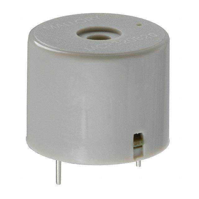
ICGOO电子元器件商城为您提供PKB24SPCH3601-B0由Murata设计生产,在icgoo商城现货销售,并且可以通过原厂、代理商等渠道进行代购。 PKB24SPCH3601-B0价格参考¥9.17-¥17.56。MurataPKB24SPCH3601-B0封装/规格:警报器,蜂鸣器,警笛, 压电 蜂鸣器 指示灯,内部驱动 12V 3.6kHz 90dB @ 12V,10cm 通孔 PC 引脚。您可以下载PKB24SPCH3601-B0参考资料、Datasheet数据手册功能说明书,资料中有PKB24SPCH3601-B0 详细功能的应用电路图电压和使用方法及教程。
Murata Electronics North America生产的PKB24SPCH3601-B0是一款压电蜂鸣器,广泛应用于需要声音警报或提示的场景。以下是其主要应用场景:

 1. 家用电器
   - 微波炉:用于加热完成时发出提示音。
   - 洗衣机/干衣机:在洗涤或烘干结束时提供声音提醒。
   - 烤箱:提示用户食物已准备好。
   - 咖啡机:咖啡制作完成后发出声音通知。

 2. 医疗设备
   - 监护仪:当患者的生命体征超出正常范围时发出警报。
   - 输液泵:液体输完或出现异常时发出警告。
   - 血糖仪:测试完成后提供声音提示。

 3. 工业设备
   - 自动化生产线:用于设备故障或任务完成时的声音报警。
   - 安全系统:如火灾报警器、气体泄漏检测仪等,用于紧急情况下的声音警示。
   - 人机界面(HMI):操作员按下按钮后,蜂鸣器可确认操作。

 4. 消费电子
   - 电子门铃:为家庭或商业场所提供访客通知。
   - 遥控器:部分遥控器在按键时会发出声音反馈。
   - 计时器:倒计时结束后发出提示音。

 5. 汽车电子
   - 倒车雷达:接近障碍物时发出警报声。
   - 胎压监测系统:胎压异常时发出声音警告。
   - 防盗报警器:车辆受到非法入侵时触发警报。

 6. 安防领域
   - 烟雾报警器:检测到烟雾时发出刺耳警报。
   - 一氧化碳探测器:检测到有害气体时发出警告。
   - 门禁系统:非法闯入或授权通过时提供声音反馈。

 7. 其他应用
   - 玩具:某些互动玩具中使用蜂鸣器增加趣味性。
   - 运动设备:如跑步机或健身器材,在特定条件下发出提示音。
   - 实验室仪器:实验完成后发出声音通知。

PKB24SPCH3601-B0凭借其小巧的尺寸、低功耗和高可靠性,适合各种需要声音提示或警报的场合。其压电技术确保了清晰且响亮的声音输出,适用于室内和轻度户外环境。
| 参数 | 数值 |
| 产品目录 | |
| 描述 | BUZZER PIEZO 15VDC 3.6KHZ PC MT音频指示器及警报器 Buzzer 24mm Self |
| 产品分类 | 蜂鸣器音频设备 |
| 品牌 | Murata Electronics |
| 产品手册 | http://search.murata.co.jp/Ceramy/CatalogAction.do?sHinnm=? &sNHinnm=PKB24SPCH3601-B0&sNhin_key=PKB24SPCH3601-B0&sLang=en&sParam=PKB24 |
| 产品图片 |
|
| rohs | 符合RoHS无铅 / 符合限制有害物质指令(RoHS)规范要求 |
| 产品系列 | 音频指示器及警报器,Murata Electronics PKB24SPCH3601-B0PK |
| 数据手册 | |
| 产品型号 | PKB24SPCH3601-B0 |
| 不同频率时的电容 | - |
| 产品 | Piezoelectric |
| 产品目录绘图 |
|
| 产品目录页面 | |
| 产品种类 | 音频指示器及警报器 |
| 其它名称 | 490-4702 |
| 包装 | 散装 |
| 可水洗 | 无 |
| 商标 | Murata Electronics |
| 声压级 | 90 dB |
| 大小/尺寸 | 圆形 - 24.30mm 直径 x 9.70mm 高 |
| 安装 | Flush |
| 安装类型 | 通孔 |
| 封装 | Bulk |
| 工作模式 | 连续 |
| 工作温度 | -20°C ~ 70°C |
| 工厂包装数量 | 650 |
| 技术 | 压电 |
| 标准包装 | 650 |
| 电压-额定 | 12VDC |
| 电压范围 | 3 ~ 15V |
| 电压额定值 | 15 VDC |
| 电流-电源 | 16mA |
| 直径 | 24.3 mm |
| 端接 | PC 引脚 |
| 系列 | PKB |
| 输入类型 | DC |
| 频率 | 3.6kHz |
| 驱动器电路 | 指示灯,内部驱动 |


- 商务部:美国ITC正式对集成电路等产品启动337调查
- 曝三星4nm工艺存在良率问题 高通将骁龙8 Gen1或转产台积电
- 太阳诱电将投资9.5亿元在常州建新厂生产MLCC 预计2023年完工
- 英特尔发布欧洲新工厂建设计划 深化IDM 2.0 战略
- 台积电先进制程称霸业界 有大客户加持明年业绩稳了
- 达到5530亿美元!SIA预计今年全球半导体销售额将创下新高
- 英特尔拟将自动驾驶子公司Mobileye上市 估值或超500亿美元
- 三星加码芯片和SET,合并消费电子和移动部门,撤换高东真等 CEO
- 三星电子宣布重大人事变动 还合并消费电子和移动部门
- 海关总署:前11个月进口集成电路产品价值2.52万亿元 增长14.8%

PDF Datasheet 数据手册内容提取
P37E.pdf Feb.5,2018 Piezoelectric Sound Components
!Note (cid:129) Please read rating and !CAUTION (for storage, operating, rating, soldering, mounting and handling) in this catalog to prevent smoking and/or burning, etc. P37E.pdf (cid:129) This catalog has only typical specifications. Therefore, please approve our product specifications or transact the approval sheet for product specifications before ordering. Feb.5,2018 EU RoHS Compliant (cid:70)(cid:3)(cid:5)(cid:42)(cid:42)(cid:3)(cid:50)(cid:38)(cid:35)(cid:3)(cid:46)(cid:48)(cid:45)(cid:34)(cid:51)(cid:33)(cid:50)(cid:49)(cid:3)(cid:39)(cid:44)(cid:3)(cid:50)(cid:38)(cid:39)(cid:49)(cid:3)(cid:33)(cid:31)(cid:50)(cid:31)(cid:42)(cid:45)(cid:37)(cid:3)(cid:33)(cid:45)(cid:43)(cid:46)(cid:42)(cid:55)(cid:3) (cid:53)(cid:39)(cid:50)(cid:38)(cid:3)(cid:9)(cid:25)(cid:3)(cid:22)(cid:45)(cid:12)(cid:23)(cid:64) (cid:70)(cid:3)(cid:9)(cid:25)(cid:3)(cid:22)(cid:45)(cid:12)(cid:23)(cid:3)(cid:39)(cid:49)(cid:3)(cid:159)(cid:50)(cid:38)(cid:35)(cid:3)(cid:9)(cid:51)(cid:48)(cid:45)(cid:46)(cid:35)(cid:31)(cid:44)(cid:3)(cid:8)(cid:39)(cid:48)(cid:35)(cid:33)(cid:50)(cid:39)(cid:52)(cid:35)(cid:3) (cid:124)(cid:122)(cid:123)(cid:123)(cid:71)(cid:128)(cid:127)(cid:71)(cid:9)(cid:25)(cid:3)(cid:45)(cid:44)(cid:3)(cid:50)(cid:38)(cid:35)(cid:3)(cid:22)(cid:35)(cid:49)(cid:50)(cid:48)(cid:39)(cid:33)(cid:50)(cid:39)(cid:45)(cid:44)(cid:3)(cid:45)(cid:36)(cid:3)(cid:50)(cid:38)(cid:35)(cid:3) (cid:25)(cid:49)(cid:35)(cid:3)(cid:45)(cid:36)(cid:3)(cid:7)(cid:35)(cid:48)(cid:50)(cid:31)(cid:39)(cid:44)(cid:3)(cid:12)(cid:31)(cid:56)(cid:31)(cid:48)(cid:34)(cid:45)(cid:51)(cid:49)(cid:3)(cid:23)(cid:51)(cid:32)(cid:49)(cid:50)(cid:31)(cid:44)(cid:33)(cid:35)(cid:49)(cid:3)(cid:39)(cid:44)(cid:3) (cid:9)(cid:42)(cid:35)(cid:33)(cid:50)(cid:48)(cid:39)(cid:33)(cid:31)(cid:42)(cid:3)(cid:31)(cid:44)(cid:34)(cid:3)(cid:9)(cid:42)(cid:35)(cid:33)(cid:50)(cid:48)(cid:45)(cid:44)(cid:39)(cid:33)(cid:3)(cid:9)(cid:47)(cid:51)(cid:39)(cid:46)(cid:43)(cid:35)(cid:44)(cid:50)(cid:64)(cid:159)(cid:3) (cid:70)(cid:3)For(cid:3)(cid:43)(cid:45)(cid:48)(cid:35)(cid:3)(cid:34)(cid:35)(cid:50)(cid:31)(cid:39)(cid:42)(cid:49)(cid:65)(cid:3)(cid:46)(cid:42)(cid:35)(cid:31)(cid:49)(cid:35)(cid:3)(cid:48)(cid:35)(cid:36)(cid:35)r(cid:3)(cid:50)o(cid:3)(cid:45)ur(cid:3)(cid:53)(cid:35)(cid:32)(cid:3) (cid:46)(cid:31)(cid:37)(cid:35)(cid:65)(cid:3)(cid:159)(cid:17)(cid:51)(cid:48)(cid:31)(cid:50)(cid:31)(cid:158)(cid:49)(cid:3)(cid:5)(cid:46)(cid:46)(cid:48)(cid:45)(cid:31)(cid:33)(cid:38)(cid:3)(cid:36)(cid:45)(cid:48)(cid:3)(cid:9)(cid:25)(cid:3)(cid:22)(cid:45)(cid:12)(cid:23)(cid:159)(cid:3) (cid:72)(cid:38)(cid:50)(cid:50)(cid:46)(cid:49)(cid:66)(cid:71)(cid:71)(cid:53)(cid:53)(cid:53)(cid:64)(cid:43)(cid:51)(cid:48)(cid:31)(cid:50)(cid:31)(cid:64)(cid:33)(cid:45)(cid:43)(cid:71)(cid:35)(cid:44)(cid:81)(cid:35)(cid:51)(cid:71)(cid:49)(cid:51)(cid:46)(cid:46)(cid:45)(cid:48)(cid:50)(cid:71) (cid:33)(cid:45)(cid:43)(cid:46)(cid:42)(cid:39)(cid:31)(cid:44)(cid:33)(cid:35)(cid:71)(cid:48)(cid:45)(cid:38)(cid:49)(cid:74)(cid:64)(cid:3)
!Note (cid:129) Please read rating and !CAUTION (for storage, operating, rating, soldering, mounting and handling) in this catalog to prevent smoking and/or burning, etc. P37E.pdf (cid:129) This catalog has only typical specifications. Therefore, please approve our product specifications or transact the approval sheet for product specifications before ordering. Feb.5,2018 1 Contents Product specifications are as of January 2018. 2 Part Numbering p2 1 Piezoelectric Sounders SMD Type Product Lineup p4 Pin Type Product Lineup p8 3 Pin Type Taping Product Lineup p11 Drive Method p13 !Caution · Notice p14 2 Piezoelectric Buzzers Product Lineup p16 !Caution · Notice p17 3 Piezoelectric Diaphragms Product Lineup p19 Design Procedures · Drive Method p20 !Caution · Notice p21 Oscillating System p23 To Raise Sound Pressure Level (S.P.L.) p24 Measuring Method p25 Minimum Quantity p26 Please check the MURATA website (https://www.murata.com/) if you cannot find a part number in this catalog.
!Note (cid:129) Please read rating and !CAUTION (for storage, operating, rating, soldering, mounting and handling) in this catalog to prevent smoking and/or burning, etc. P37E.pdf (cid:129) This catalog has only typical specifications. Therefore, please approve our product specifications or transact the approval sheet for product specifications before ordering. Feb.5,2018 o Part Numbering SMD Piezoelectric Sounder (Part Number) PK LCS 1212 E 40 ** -R1 1 2 3 4 5 6 7 1Product ID 4Drive Product ID Code Drive PK Piezoelectric Sound Components E External Drive 2Product 5Oscillating Frequency Type Code Product Expressed resonant frequency by two-digit alphanumerics. The LCS/MCS SMD Sounder unit is in 100 hertz (Hz.) 4kHz (4000Hz) is denoted as "40." 6Individual Specification Code 3Dimensions Code Individual Specification Code Code Outer Dimensions 1818 p18mm ** Two digits express specific specification in characteristics. 1212 p12mm 0909 p9mm 7Packaging Code Packaging -R1 Plastic Taping Pin Type Piezoelectric Sounders/Piezoelectric Buzzers (Part Number) PK M 13 E P YH 40 ** P -A0 1 2 3 4 5 6 7 8 9 : 1Product ID 7Oscillating Frequency Type Product ID Expressed resonant frequency by two-digit alphanumerics. The PK Piezoelectric Sound Components unit is in 100 hertz (Hz). In case of 4kHz (4000Hz), expressed as "40." 2Product 8Individual Specification Code Code Product Code Individual Specification Code M Sounder Two digits express custom specification in ** B Buzzer characteristics. 3Outer Dimensions 9Special Quality Guarantee Expressed by two figures in mm. Code Special Quality Guarantee Ex.) Code Outer Dimensions P Post Plated Terminal 13 ø12.6mm e Not Post Plated Terminal (Blank) 4Drive :Packaging Code Drive Code Packaging E External-Drive -B0 Bulk S Self-Drive -A0 Radial Taping Radial taping is not available for all types. 5Outer Electrode Style Please contact us. Code Outer Electrode Style P Pin Type 6Structure Code Structure Pp Flat Type Auto-assemble Yp Flat Type/Available for Taping Cp Flat Type/Semi-auto-assemble p Exclude above mentioned p signifies specification of the outer electrode. 2
!Note (cid:129) Please read rating and !CAUTION (for storage, operating, rating, soldering, mounting and handling) in this catalog to prevent smoking and/or burning, etc. P37E.pdf (cid:129) This catalog has only typical specifications. Therefore, please approve our product specifications or transact the approval sheet for product specifications before ordering. Feb.5,2018 Piezoelectric Diaphragms (Part Number) 7 N B -**** -1R5 L 10 1 2 3 4 5 6 7 1Product ID 5Resonant Frequency Type Product ID A hyphen (-) and three-digit alphanumerics express resonant 7 Ceramic Material frequency. A decimal point is expressed by the capital letter "R." If there is no decimal point, the decimal point code is omitted. 2Metal Plate Material 6Product Specification Code Metal Plate Material Code Product Specification B Brass L With lead (available for RoHS) N Nickel Alloy e No lead (omitted) 3Product 7Individual Specification Code Code Product These digits express a lead length, lead number, and the B Piezoelectric Diaphragms presence/absence of a connector. If the product has no individual specification, the corresponding code is omitted. 4Metal Plate Diameter Code Metal Plate Diameter A hyphen (-) plus from two to four-digit alphanumerics express metal plate outer -**** dimensions. A decimal point is expressed by the capital letter "R." 3
!Note (cid:129) Please read rating and !CAUTION (for storage, operating, rating, soldering, mounting and handling) in this catalog to prevent smoking and/or burning, etc. P37E.pdf (cid:129) This catalog has only typical specifications. Therefore, please approve our product specifications or transact the approval sheet for product specifications before ordering. Feb.5,2018 Piezoelectric Sound Components 1 RoHS Piezoelectric Sounders SMD Type 4) (3.3) 3.0 max. Taking advantage of extensive acoustic and mechanical (0. Sound Emitting Hole design technology and high performance ceramics, 12.0 (ø0.15) Open Hole Murata has developed SMD piezoelectric sounders that (3.0) 1.1 0) suit the thin, high-density design of electronic PKLCS1212E2000-R1 (3. equipment. PKLCS1212E20A0-R1 * 12.0 4.0 Marking Features :PKLCS1212E2000-R1 PKLCS1212E20A0-R1 :PKLCS1212E2400-R1 1. Small, thin and lightweight PKLCS1212E24A0-R1 2. High sound pressure level and clear sound ( ): Ref. only 3. Reflowable PKLCS1212E2400-R1 10.0 To(iln.: m±0m.2) PKLCS1212E24A0-R1 (Note) The location of open hole is not specified. 4. Tape & Reel supply (0.9) 3.0 max. (1.5) 9(1.0.5) Open Hole 0.6 (1.9) Sound Emitting Hole 12.0 1.2 9.0 3.2 max. 12.0 4.0 (0.3) 1.9 7) (2.0) Sound Emitting Hole 0. ( (6.4) 10.0 5) 1. ( PKLCS1212E4001-R1 1) PKMCS0909E4000-R1 PKLCS1212E40A1-R1 (2. ( ): Ref. only 1.0 ( ): TRoelf.:. ±o0n.l2y Tol.: ±0.2 (in mm) (Note) The location of open hole is not specified. (in mm) Sound Emitting Hole (0.4) 4) 18.0 0.95 1. (2.0) 4.2)( 8.0 (3.2)(4.5) 6.4 (1 1 6.4 2.7 (1.8) (6.1) 0 max.(1.4) (14.2) (0.8) 8. 0) P+otlae+rrimtyi:n al (Hot Side of D.C.) (10.4) (0.4) (1. -terminal (0V) 16.0 -Tarminal +Tarminal PKMCS1818E20A0-R1 ( ): Ref. only Tol.: ±0.2 1.0 1.0 (in mm) For Consumer Sound Pressure Level Operating Capacitance Operating Storage Part Number Voltage Range* (nF) Temp. Range Temp. Range (typ.) (Vo-p) Ref. only (°C) (°C) PKLCS1212E2000-R1 76dB [±1.5Vo-p,2.0kHz,square wave,10cm] ±12.5 max. (28.0) -20 to +70 -30 to +80 PKLCS1212E2400-R1 80dB [±1.5Vo-p,2.4kHz,square wave,10cm] ±12.5 max. (28.0) -20 to +70 -30 to +80 PKLCS1212E4001-R1 84dB [±1.5Vo-p,4.0kHz,square wave,10cm] ±12.5 max. (19.5) -20 to +70 -30 to +80 PKMCS0909E4000-R1 72dB [±1.5Vo-p,4.0kHz,square wave,10cm] ±12.5 max. (9.0) -40 to +85 -40 to +85 *Operating Voltage Range: Does not contain Direct Current bias. 4
!Note (cid:129) Please read rating and !CAUTION (for storage, operating, rating, soldering, mounting and handling) in this catalog to prevent smoking and/or burning, etc. P37E.pdf (cid:129) This catalog has only typical specifications. Therefore, please approve our product specifications or transact the approval sheet for product specifications before ordering. Feb.5,2018 For Automotive Sound Pressure Level Operating Capacitance Operating Storage 1 Part Number Voltage Range* (nF) Temp. Range Temp. Range (typ.) (Vo-p) Ref. only (°C) (°C) PKLCS1212E20A0-R1 76dB [±1.5Vo-p,2.0kHz,square wave,10cm] ±12.5 max. (28.0) -40 to +85 -40 to +85 PKLCS1212E24A0-R1 80dB [±1.5Vo-p,2.4kHz,square wave,10cm] ±12.5 max. (28.0) -40 to +85 -40 to +85 PKLCS1212E40A1-R1 84dB [±1.5Vo-p,4.0kHz,square wave,10cm] ±12.5 max. (19.5) -40 to +85 -40 to +85 PKMCS1818E20A0-R1 100dB [12Vo-p,2.0kHz,square wave,10cm] 18.0Vo-p [with polarity] (37.0) -40 to +105 -40 to +105 *Operating Voltage Range: Does not contain Direct Current bias. Standard Land Pattern Dimensions PKLCS1212E Series PKMCS0909E Series 12.4 10.0 10.0 7.4 4 4.0 3. (in mm) (in mm) PKMCS1818E Series 18.4 1.2 1.2 4 6. 7 2. 16.0 4 6. (in mm) Frequency Response PKLCS1212E2000-R1 / PKLCS1212E20A0-R1 PKLCS1212E2400-R1 / PKLCS1212E24A0-R1 Conditions: 10cm, A-filter Conditions: 10cm, A-filter 100 100 Square wave, ±1.5Vo-p Square wave, ±1.5Vo-p 95 95 90 90 B) B) el (d 85 el (d 85 ev 80 ev 80 L L e e ur 75 ur 75 s s s s Pre 70 Pre 70 d d n 65 n 65 u u o o S 60 S 60 55 55 50 50 0 1 2 3 4 5 6 7 8 9 10 0 1 2 3 4 5 6 7 8 9 10 Frequency (kHz) Frequency (kHz) Continued on the following page. 5
!Note (cid:129) Please read rating and !CAUTION (for storage, operating, rating, soldering, mounting and handling) in this catalog to prevent smoking and/or burning, etc. P37E.pdf (cid:129) This catalog has only typical specifications. Therefore, please approve our product specifications or transact the approval sheet for product specifications before ordering. Feb.5,2018 Continued from the preceding page. Frequency Response PKLCS1212E4001-R1 / PKLCS1212E40A1-R1 PKMCS0909E4000-R1 1 Conditions: 10cm, A-filter Conditions: 10cm, A-filter 100 100 Square wave, ±1.5Vo-p Square wave, ±1.5Vo-p 95 95 90 90 B) B) el (d 85 el (d 85 ev 80 ev 80 L L e e ur 75 ur 75 s s s s Pre 70 Pre 70 d d n 65 n 65 u u o o S 60 S 60 55 55 50 50 0 1 2 3 4 5 6 7 8 9 10 0 1 2 3 4 5 6 7 8 9 10 Frequency (kHz) Frequency (kHz) PKMCS1818E20A0-R1 Conditions: 10cm, A-filter 120 Square Wave, 12Vo-p 110 B) d100 el ( v e L 90 e ur s es 80 Pr d un 70 o S 60 50 0 1 2 3 4 Frequency (kHz) Taping Dimension PKLCS1212E Series Dimensions of Carrier Tape Dimensions of Reel 4.0±0.1 ø1.50+-00..10 ±0.1 2.0±0.1 5 1.7 T1r6ai0le–r200 Components Cover Film 1 0. ± 11.5 4.0±0.2 2.5±0.1 (ø80) (ø330) 2.2±0.2 24E0m–p42t08y00–560 2 1 Leader 25.5±0.5 33.5 max. 13.0±0.2 16.0±0.1 3.1±0.1 Direction of Feed Cover film peel strength force: 0.1–0.7N Cover film peel speed: 300mm/min. Cover Film 12.5±0.1 10° (in mm) 6
!Note (cid:129) Please read rating and !CAUTION (for storage, operating, rating, soldering, mounting and handling) in this catalog to prevent smoking and/or burning, etc. P37E.pdf (cid:129) This catalog has only typical specifications. Therefore, please approve our product specifications or transact the approval sheet for product specifications before ordering. Feb.5,2018 Taping Dimension PKMCS0909E Series 1 Dimensions of Plastic Tape Dimensions of Plastic Reel 1 4.0±0.1 0. Trailer 2.0±0.1 ø1.5–+00..10 75± 0.3±0.1 160 to 200 1. Components Cover film 1 0. 3 9.5±0.1 00* 00* 00* 00* 7.5± 16.0±0. (ø80) (ø330) 2.0±0.5 24E0m top t2y80 400 to 560 Leader 9.5±0.1 12.0±0.1 Direction of Feed 2.4±0.2 ø13.0±0.5 17.4±1.0 Cover Film 10° 22.5 max. Cover film peel strength force 0.1 to 0.7N Cover film peel speed 300mm/min. (in mm) Taping Dimension PKMCS1818E Series Dimensions of Carrier Tape Dimensions of Reel 4.0±0.1 ø1.50+-00..01 0.1 ± 2.0±0.1 5 8.3±0.1 7 1. Trailer Components 160–200 1 Cover Film 0. ± 2 14. 32.0±0.3 18.4±0.1 (ø80) (ø330) 2.2±0.2 24E0m–p42t08y00–560 Leader 33.5±0.5 1 1 41.5 max. 24±0.1 1.5±0.1 0. 0. 13.0±0.2 ± ± 7 2 1. 0. Direction of Feed The cover film peel strength force: 0.1 to 0.7N The cover film peel speed: 300mm/min. Cover Film 18.4±0.1 10° (in mm) 7
!Note (cid:129) Please read rating and !CAUTION (for storage, operating, rating, soldering, mounting and handling) in this catalog to prevent smoking and/or burning, etc. P37E.pdf (cid:129) This catalog has only typical specifications. Therefore, please approve our product specifications or transact the approval sheet for product specifications before ordering. Feb.5,2018 Piezoelectric Sound Components 1 RoHS Piezoelectric Sounders Pin Type Microcomputers are widely used for microwave ovens, air conditioners, cars, toys, timers, and alarm equipment. Externally driven piezoelectric sounders are used in digital watches, electronic ø12.6 calculators, telephones and other equipment. 0.9 6.9 They are driven by a signal (ex.: 2048Hz or 4096Hz) 3.5 from an LSI and provide melodious sound. 2–ø0.5 5.0 2–ø1.0 Features PKM13EPYH4002-B0 5 7. 2–ø2.5 1. Low power consumption (in mm) Tol.: ±0.5 2. Noiseless and highly reliability Applications 1. Various office equipment such as PPCs printers and keyboards R1.0 2. Home appliances such as microwave oven, rice cookers etc. 8.6 2 3. Confirmation sound of various audio equipment 3.5 1. 10.0 Terminal of marking ø17.0 side should be connected to hot side of D.C. 2-ø1.2 0 PKM17EPP-2002-B0 1. 2-ø3.5 1 (in mm) Tol.: ±0.5 12.6 Hole Pattern (Reference) R1.0 10.54.8 20° 4.7 8.0 223-ø.01.5 7.0 1.2 1.6 0.8 ø22.0 10.0 ø17.0 2-ø1.2 0 11.0 8.3 5.0 6. 2-ø3.5 5.0 (in mm) 4.0 (Tino lm.: ±m0).5 PKM17EPPH4001-B0 Tol.: ±0.5 PKM22EPH2001 Part Number Part Number PKM22EPH2001 4.0 PKM17EPPH4001-B0 6.5 PKM22EPH2002 8.0 PKM17EPPH4002-B0 3.5 PKM22EPH2003 12.0 R1.0 R1.0 10.81.2 7.01.2 0.8 0.8 10.0 10.0 ø22.0 ø22.0 2–ø1.2 2–ø1.2 10.0 10.0 2–ø3.5 (in mm) 2–ø3.5 (in mm) PKM22EPPH2001-B0 Tol.: ±0.5 PKM22EPPH4001-B0 Tol.: ±0.5 Part Number Part Number PKM22EPPH2001-B0 6.5 PKM22EPPH4001-B0 6.5 PKM22EPPH2002-B0 3.5 PKM22EPPH4002-B0 3.5 8
!Note (cid:129) Please read rating and !CAUTION (for storage, operating, rating, soldering, mounting and handling) in this catalog to prevent smoking and/or burning, etc. P37E.pdf (cid:129) This catalog has only typical specifications. Therefore, please approve our product specifications or transact the approval sheet for product specifications before ordering. Feb.5,2018 1 R1.0 R15.0 1.2 8.2 0.8 10.8 1.2 3. 0.8 10.0 6.5 ø1202.0.0 ø22.0 2-ø1.2 ø1.2 3–ø1.5 0 PKM22EPPH4005-B0 32––øø13..7518° R8.5 °81 5.05.0 PKM22EPPH4007-B0 2-ø3.5 10. (Tino lm.: ±m0).5 120° 120° (in mm) PKMP2a2rEtP NPuHm4b0e0r7-B0 6.5 Tol.: ±0.5 PKM22EPPH4012-B0 3.5 Sound Pressure Level Operating Capacitance Operating Storage Part Number Voltage Range* Temp. Range Temp. Range (typ.) (Vo-p) (nF) (°C) (°C) PKM13EPYH4002-B0 78dB [±1.5Vo-p,4.0kHz, square wave,10cm] ±15.0 max. 5.5 ±30%[1kHz] -40 to +85 -40 to +85 PKM17EPP-2002-B0 79dB [3.0Vo-p,2.0kHz, square wave,10cm] 25.0 max. [with polarity] 34.0 ±30%[120Hz] -20 to +70 -30 to +80 PKM17EPPH4001-B0 79dB [±1.5Vo-p,4.0kHz,square wave,10cm] ±12.5 max. 7.0 ±30%[1kHz] -20 to +70 -30 to +80 PKM22EPH2001 85dB [±1.5Vo-p,2.0kHz,square wave,10cm] ±12.5 max. 17.0 ±30%[120Hz] -20 to +70 -30 to +80 PKM22EPPH2001-B0 79dB [±1.5Vo-p,2.0kHz,square wave,10cm] ±15.0 max. 19.0 ±30%[120Hz] -20 to +70 -30 to +80 PKM22EPPH4001-B0 87dB [±1.5Vo-p,4.0kHz,square wave,10cm] ±15.0 max. 12.0 ±30%[1kHz] -20 to +70 -30 to +80 PKM22EPPH4005-B0 86dB [±1.5Vo-p,4.0kHz,square wave,10cm] ±15.0 max. 12.0 ±30%[1kHz] -20 to +70 -30 to +80 PKM22EPPH4007-B0 92dB [±1.5Vo-p,4.0kHz,square wave,10cm] ±15.0 max. 12.0 ±30%[1kHz] -20 to +70 -30 to +80 *Operating Voltage Range: Does not contain Direct Current bias. Frequency Response PKM13EPYH4002-B0 PKM17EPP-2002-B0 Conditions: 10cm, A-filter Conditions: 10cm, A-filter 100 100 Square wave, ±1.5Vo-p Square wave, ±1.5Vo-p 95 95 90 90 B) B) el (d 85 el (d 85 ev 80 ev 80 L L e e ur 75 ur 75 s s s s Pre 70 Pre 70 d d n 65 n 65 u u o o S 60 S 60 55 55 50 50 0 1 2 3 4 5 6 7 8 9 10 0 1 2 3 4 5 6 7 8 9 10 Frequency (kHz) Frequency (kHz) PKM17EPPH4001-B0 PKM22EPH2001 Conditions: 10cm, A-filter Conditions: 10cm, A-filter 100 100 Square wave, ±1.5Vo-p Square wave, ±1.5Vo-p 95 95 90 90 B) B) el (d 85 el (d 85 ev 80 ev 80 L L e e ur 75 ur 75 s s s s Pre 70 Pre 70 d d n 65 n 65 u u o o S 60 S 60 55 55 50 50 0 1 2 3 4 5 6 7 8 9 10 0 1 2 3 4 5 6 7 8 9 10 Frequency (kHz) Frequency (kHz) Continued on the following page. 9
!Note (cid:129) Please read rating and !CAUTION (for storage, operating, rating, soldering, mounting and handling) in this catalog to prevent smoking and/or burning, etc. P37E.pdf (cid:129) This catalog has only typical specifications. Therefore, please approve our product specifications or transact the approval sheet for product specifications before ordering. Feb.5,2018 Continued from the preceding page. Frequency Response PKM22EPPH2001-B0 PKM22EPPH4001-B0 1 Conditions: 10cm, A-filter Conditions: 10cm, A-filter 100 100 Square wave, ±1.5Vo-p Square wave, ±1.5Vo-p 95 95 90 90 B) B) el (d 85 el (d 85 ev 80 ev 80 L L e e ur 75 ur 75 s s s s Pre 70 Pre 70 d d n 65 n 65 u u o o S 60 S 60 55 55 50 50 0 1 2 3 4 5 6 7 8 9 10 0 1 2 3 4 5 6 7 8 9 10 Frequency (kHz) Frequency (kHz) PKM22EPPH4005-B0 PKM22EPPH4007-B0 Conditions: 10cm, A-filter Conditions: 10cm, A-filter 100 100 Square wave, ±1.5Vo-p Square wave, ±1.5Vo-p 95 95 90 90 B) B) el (d 85 el (d 85 ev 80 ev 80 L L e e ur 75 ur 75 s s s s Pre 70 Pre 70 d d n 65 n 65 u u o o S 60 S 60 55 55 50 50 0 1 2 3 4 5 6 7 8 9 10 0 1 2 3 4 5 6 7 8 9 10 Frequency (kHz) Frequency (kHz) 10
!Note (cid:129) Please read rating and !CAUTION (for storage, operating, rating, soldering, mounting and handling) in this catalog to prevent smoking and/or burning, etc. P37E.pdf (cid:129) This catalog has only typical specifications. Therefore, please approve our product specifications or transact the approval sheet for product specifications before ordering. Feb.5,2018 Piezoelectric Sound Components 1 RoHS Piezoelectric Sounders Pin Type Taping Taking advantage of extensive automatic insertion design technology and materials experience, Murata has developed standard taping type piezoelectric ø12.6 sounders. 0.96.9 This Murata technology supports labor and cost saving 5.0 measures. 0 2–ø0.5 22. Features 2–ø1.0 1. Lead dimension: Improved mounting reliability 5 7. (cut & clinch) due to round terminal 2–ø2.5 (in mm) Tol.: ±0.5 2. High, stable mountability 3. Ammo packaging Sound Pressure Level Operating Capacitance Operating Storage Part Number Voltage Range* Temp. Range Temp. Range (typ.) (Vo-p) (nF) (°C) (°C) PKM13EPYH4000-A0 78dB [±1.5Vo-p,4.0kHz,square wave,10cm] ±15.0max. 5.5 ±30%[1kHz] -40 to +85 -40 to +85 *Operating Voltage Range: Does not contain Direct Current bias. Frequency Response PKM13EPYH4000-A0 Conditions: 10cm, A-filter 100 Square wave, ±1.5Vo-p 95 90 B) el (d 85 ev 80 L e ur 75 s s Pre 70 d n 65 u o S 60 55 50 0 1 2 3 4 5 6 7 8 9 10 Frequency (kHz) 11
!Note (cid:129) Please read rating and !CAUTION (for storage, operating, rating, soldering, mounting and handling) in this catalog to prevent smoking and/or burning, etc. P37E.pdf (cid:129) This catalog has only typical specifications. Therefore, please approve our product specifications or transact the approval sheet for product specifications before ordering. Feb.5,2018 Taping Dimension 1 dh dh P2 P dS D A d1 W2 H1 0 H 1 W L1 W0 W P1 F D0 t P0 Item Code Nominal Value Tol. Notes Width of diameter D ø12.6 ±0.5 Height of component A 6.9 ±0.5 Dimensions of terminal d1 ø0.5 ±0.1 Lead length under the L1 8.0 min. — hold-down tape Pitch of component P 25.4 ±0.5 Pitch of sprocket P0 12.7 ±0.2 Tolerance for Pitches 10xP0=127±2mm Length from hole center to lead P1 3.85 ±0.7 Length from hole center to P2 6.35 ±0.7 component center Lead spacing F 5.0 ±0.5 Slant forward or backward dh 0 ±1.0 360°: 1mm max. Width of carrier tape W 18.0 ±0.5 Width of hold-down tape W0 12.5 min. — Hold-down tape does not exceed the carrier tape. Position of sprocket hole W1 9.0 ±0.5 Gap of hold-down tape and W2 2.0 max. — carrier tape Distance between the center of H0 18.0 ±0.5 sprocket hole and lead stopper Total height of component H1 26.0 max. — Diameter of sprocket hole D0 ø4.0 ±0.2 Total thickness of tape t 0.6 ±0.2 Body tilt dS 0 ±1.0 (in mm) 12
!Note (cid:129) Please read rating and !CAUTION (for storage, operating, rating, soldering, mounting and handling) in this catalog to prevent smoking and/or burning, etc. P37E.pdf (cid:129) This catalog has only typical specifications. Therefore, please approve our product specifications or transact the approval sheet for product specifications before ordering. Feb.5,2018 Drive Method 1 Fig. 1 shows examples of the circuit to which the external drive method is applied. +V ( i ) Represents a circuit driven by output signals of the unstable multivibrator. 510Ω 20kΩ 20kΩ 510Ω 1kΩ ( ii ) Represents a circuit using 2 NAND gates, which is 0.01μF 0.01μF 1kΩ oscillated or stopped by ON/OFF operations of the input signals. ( iii ) Represents a circuit driven by output signals of CMOS LSI. ( i ) 1MΩ 0.001μF +V 120kΩ 1kΩ 1kΩ Input Signal ( ii ) +V CMOS LSI 1kΩ Buzzer Drive Circuit Resonator LCD ( iii ) Fig. 1 Drive Circuit 13
!Note (cid:129) Please read rating and !CAUTION (for storage, operating, rating, soldering, mounting and handling) in this catalog to prevent smoking and/or burning, etc. P37E.pdf (cid:129) This catalog has only typical specifications. Therefore, please approve our product specifications or transact the approval sheet for product specifications before ordering. Feb.5,2018 !Caution · Notice 1 !Caution (Rating) Do not use the product beyond the rated temperature range and the rated voltage range. If using it beyond this range, characteristics might degrade. Notice (Storage and Operating Condition) 1. Product Storage Condition (2) Please do not store the products directly on the floor Please store the products in a room where the without anything under them to avoid damp places temperature/humidity is stable and avoid places where and/or dusty places. there are large temperature changes. Please store the (3) Please do not store the product in places such as in a products under the following conditions. damp heated place or any place exposed to direct Temperature: -10 to +40°C sunlight or excessive vibration. Humidity: 15 to 85%R.H. (4) Please use the products immediately after the 2. Expiration Date on Storage package is opened, because the characteristics may be Expiration date (shelf life) of the products is six months reduced in quality, and/or be degraded in solderability after delivery under the condition of a sealed and due to storage under poor conditions. unopened package. Please use the products within six (5) Please be sure to consult with our sales representative months after delivery. If you store the products for a long or engineer whenever the products are to be used in time (more than six months), use carefully because the conditions not listed above. products may be degraded in solderability due to storage 4. Operating Environment under poor conditions. This product is designed for application in an ordinary Please confirm solderability and characteristics for the environment (normal room temperature, humidity and products regularly. atmospheric pressure). 3. Notice on Product Storage Do not use the products in a chemical atmosphere such (1) Please do not store the products in a chemical as chlorine gas, acid or sulfide gas. atmosphere (Acids, Alkali, Bases, Organic gas, Sulfides Characteristics might degrade by a chemical reaction and so on), because the characteristics may be reduced with the material used in products. in quality, may be degraded in solderability due to storage in a chemical atmosphere. Notice (Soldering and Mounting) 1. Mounting (2) Soldering condition by soldering iron for pin terminal When mounting a pin terminal type of product to the type printed circuit board, please insert the pin terminal along · Temperature: within 350±5°C the hole of the board. If the product is pressed so that the · Time: within 3.0±0.5 sec. terminal is not in the hole, the pin terminal would be · Soldering part is the lead terminals excluding 1.5mm pushed into the inside of the product and the sounds from product body might become unstable. (3) Reflow soldering condition for surface mounting type 2. Double-sided through-hole Board · Temperature profile: Fig. 1 Please avoid using a double-sided through-hole board. If · Number of times: Within 2 maximum the melted solder touched the base of a pin terminal, a part of the plastic case would melt and the sounds might become unstable. Peak (260°C max.) 3. Soldering Conditions 260 230 (1) Flow soldering conditions for pin terminal type Heating C) (230°C) · Temperature: within 260°C±5°C e (° · Time: within 10±1 sec. atur Pre-heating · Soldering part is the lead terminals excluding 1.5mm per (150-180°C) m 100 from product body. Te Gradual Cooling 30 sec. 60 to 120 sec. 40 sec. 120 sec. min. max. min. Fig. 1 14 Continued on the following page.
!Note (cid:129) Please read rating and !CAUTION (for storage, operating, rating, soldering, mounting and handling) in this catalog to prevent smoking and/or burning, etc. P37E.pdf (cid:129) This catalog has only typical specifications. Therefore, please approve our product specifications or transact the approval sheet for product specifications before ordering. Feb.5,2018 !Caution · Notice 1 Continued from the preceding page. 4. Washing 6. Flux or Coating Agent, etc., Various Solvents Please avoid washing, since this product is not a sealed It is possible for a liquid solvent to penetrate inside the structure. product, since this product is not a sealed structure. If a 5. After Mounting the Product liquid penetrated inside and attached to the piezoelectric (1) If the product is floating from the printed circuit board, diaphragm, its vibration could be inhibited. If attaching to please do not push it. When pressing, the pin terminal is an electrical junction, the electric connection might fail. pushed inside the product and the sounds might To prevent sound instability, please do not allow liquid to become unstable. penetrate inside the product. (2) Please do not apply force (shock) to the product. If force is applied, the case might come off. (3) If the case comes off, please do not reassemble. Even if it seems to have returned to the original, the sounds might become unstable. (4) Please do not blow air onto the product directly. Blown air applies force to the piezoelectric diaphragm through the sound emission hole; cracks could occur and then the sounds could become unstable. In addition, there is a possibility that the case could come off. Notice (Handling) 1. Piezoelectric ceramic is used in this product. Please use care in handling, because ceramic is broken when excessive force is applied. 2. Please do not apply force to the piezoelectric diaphragm LSI Buzzer from the sound emission hole. If applying force, cracks occur and the sounds might become unstable. 3. Please do not drop the product or apply shock or Fig. 2 Protect Circuit temperature change to it. If so, the LSI might be destroyed by the charge (surge voltage) generated. Fig. 2 shows an example driving circuit using zener diode. Notice (Driving) 1. Ag migration might occur if DC voltage is applied to the product under a high humidity environment. Please avoid R using it under high humidity and design the circuit not to apply DC voltage. IC IC 2. When driving the product by IC, please insert the resistance of 1 to 2kΩ in series. The purpose is to protect the IC and to obtain stable sound. (Please see Fig. 2a). Inserting a diode in parallel to the product has the same Fig. 3a Fig. 3b effect. (Please see Fig. 3b) 15
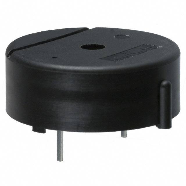
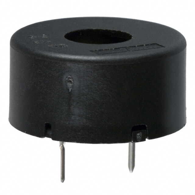
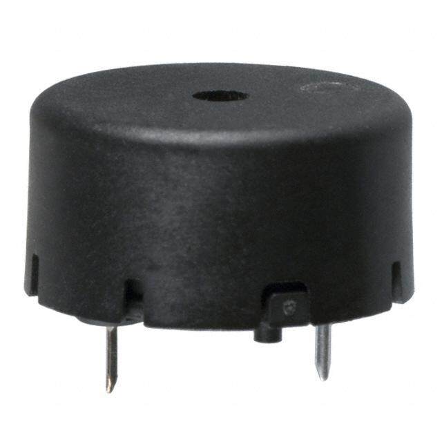
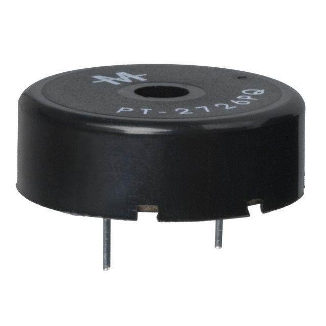
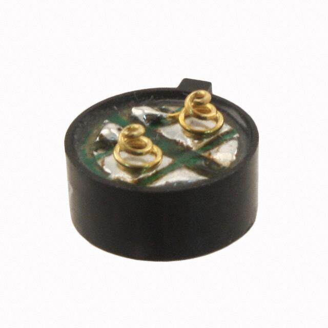
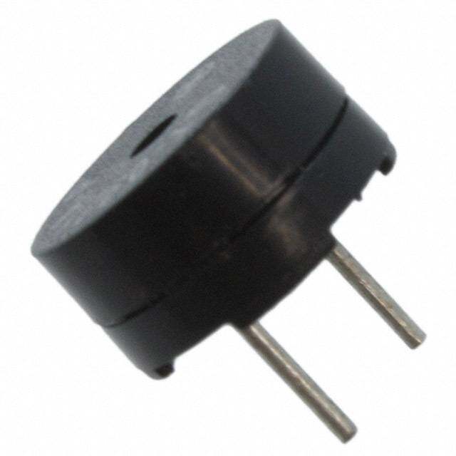
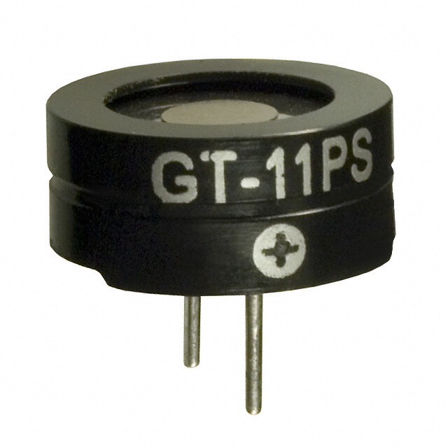
!Note (cid:129) Please read rating and !CAUTION (for storage, operating, rating, soldering, mounting and handling) in this catalog to prevent smoking and/or burning, etc. P37E.pdf (cid:129) This catalog has only typical specifications. Therefore, please approve our product specifications or transact the approval sheet for product specifications before ordering. Feb.5,2018 Piezoelectric Sound Components RoHS Piezoelectric Buzzers This is a unified piezoelectric sounder that has a piezoelectric diaphragm of 3 terminals connected to a 2 self-drive circuit, and it easily generates sound with only a DC power supply (DC3.0-15V). Using a suitably R1.0 24.3±0.3 dlaersgieg nsoedun rdes voonluamnte ssy astree mne, ethdiesd t.ype can be used where 0.7±0.39.7±0.34.5±1 15.0 Applications 0.6±0.1 1. Gas alarms, burglar alarms PKB24SPCH3601-B0 2. Air conditioners, microwave ovens and various types of (in mm) Tol.: ±0.5 microcomputer controlled home electronic appliances 3. Toys, games, and other simple electronic devices such as teaching aids Sound Oscillating Current Operating Operating Storage Part Number Pressure Level Frequency Consumption Voltage Range Temp. Range Temp. Range (min.) (kHz) (mA) (Vdc) (°C) (°C) 90dB 3.6 ±0.5kHz 16 max. PKB24SPCH3601-B0 3.0 to 15.0 -20 to +70 -30 to +80 [12Vdc,10cm] [12Vdc] [12Vdc] Voltage-Sound Pressure Level/Voltage-Consumption Current 110 25 dB) mA) Sound Pressure Level (10900 Sound Pressure LCevoenlsumption Current 211050 Consumption Current ( 5 80 0 5 10 15 Input Voltage (Vdc) 16
!Note (cid:129) Please read rating and !CAUTION (for storage, operating, rating, soldering, mounting and handling) in this catalog to prevent smoking and/or burning, etc. P37E.pdf (cid:129) This catalog has only typical specifications. Therefore, please approve our product specifications or transact the approval sheet for product specifications before ordering. Feb.5,2018 !Caution · Notice !Caution (Rating) Do not use the product beyond the rated temperature range and the rated voltage range. If using it beyond this range, characteristics might degrade. 2 Notice (Storage and Operating Condition) 1. Product Storage Condition (2) Please do not store the products directly on the floor Please store the products in a room where the without anything under them to avoid damp places temperature/humidity is stable and avoid places where and/or dusty places. there are large temperature changes. Please store the (3) Please do not store the product in places such as in a products under the following conditions. damp heated place or any place exposed to direct Temperature: -10 to +40°C sunlight or excessive vibration. Humidity: 15 to 85%R.H. (4) Please use the products immediately after the 2. Expiration Date on Storage package is opened, because the characteristics may be Expiration date (shelf life) of the products is six months reduced in quality, and/or be degraded in solderability after delivery under the condition of a sealed and due to storage under poor conditions. unopened package. Please use the products within six (5) Please be sure to consult with our sales representative months after delivery. If you store the products for a long or engineer whenever the products are to be used in time (more than six months), use carefully because the conditions not listed above. products may be degraded in solderability due to storage 4. Operating Environment under poor conditions. This product is designed for application in an ordinary Please confirm solderability and characteristics for the environment (normal room temperature, humidity and products regularly. atmospheric pressure). 3. Notice on Product Storage Do not use the products in a chemical atmosphere such (1) Please do not store the products in a chemical as chlorine gas, acid or sulfide gas. atmosphere (Acids, Alkali, Bases, Organic gas, Sulfides Characteristics might degrade by a chemical reaction and so on), because the characteristics may be reduced with the material used in products. in quality, may be degraded in solderability due to storage in a chemical atmosphere. Notice (Soldering and Mounting) 1. Mounting · Time: within 3.0±0.5 sec. When mounting a pin terminal type of product to the · Soldering part is the lead terminals excluding 1.5mm printed circuit board, please insert the pin terminal along from product body. the hole of the board. If the product is pressed so that the 4. Washing terminal is not in the hole, the pin terminal would be Please avoid washing, since this product is not a sealed pushed into the inside of the product and the sounds structure. might become unstable. 5. After Mounting the Product 2. Double-sided through-hole Board (1) If the product is floating from the printed circuit board, Please avoid using a double-sided through-hole board. If please do not push it. When pressing, the pin terminal is the melted solder touched the base of a pin terminal, a pushed inside the product and the sounds might part of the plastic case would melt and the sounds might become unstable. become unstable. (2) Please do not apply force (shock) to the product. If 3. Soldering Conditions force is applied, the case might come off. (1) Flow soldering conditions for pin terminal type (3) If the case comes off, please do not reassemble. Even · Temperature: within +260°C±5°C if it seems to have returned to the original, the sounds · Time: within 10±1 sec. might become unstable. · Soldering part is the lead terminals excluding 1.5mm (4) Please do not blow air onto the product directly. from product body. Blown air applies force to the piezoelectric diaphragm (2) Soldering condition by soldering iron for pin terminal through the sound emission hole; cracks could occur type and then the sounds could become unstable. · Temperature: within 350±5°C Continued on the following page. 17
!Note (cid:129) Please read rating and !CAUTION (for storage, operating, rating, soldering, mounting and handling) in this catalog to prevent smoking and/or burning, etc. P37E.pdf (cid:129) This catalog has only typical specifications. Therefore, please approve our product specifications or transact the approval sheet for product specifications before ordering. Feb.5,2018 !Caution · Notice Continued from the preceding page. 6. Flux or Coating Agent, etc., Various Solvents It is possible for a liquid solvent to penetrate inside the product, since this product is not a sealed structure. If a liquid penetrated inside and attached to the piezoelectric diaphragm, its vibration could be inhibited. If attaching to an electrical junction, the electric connection might fail. 2 To prevent sound instability, please do not allow liquid to penetrate inside the product. Notice (Handling) 1. Piezoelectric ceramic is used in this product. Please use care in handling, because ceramic is broken when excessive force is applied. 2. Please do not apply force to the piezoelectric diaphragm LSI Buzzer from the sound emission hole. If applying force, cracks occur and the sounds might become unstable. 3. Please do not drop the product or apply shock or Fig. 1 Protect Circuit temperature change to it. If so, the LSI might be destroyed by the charge (surge voltage) generated. Notice (Driving) 1. When using a piezoelectric buzzer, there is no need to prepare the oscillation circuit; it has an oscillation circuit. +Vdc 2. Please set the sounding time more than 200 msec., when driving the piezoelectric sounder of self-drive or the piezoelectric buzzer as an intermittent sound. 3. Please don’t block the sound emission hole with tape to control the sound volume. The oscillation circuit condition is set so as to obtain a stable sounding (oscillating) state under the condition that the front of sound emission hole Capacitor Buzzer (1μF) is in an open state. If the sound emission hole is blocked with tape, then the oscillation condition changes and the sounds might become unstable. 4. Please don’t put a resistor between the oscillation circuit Fig. 2 and power supply to control the sound volume of the piezoelectric sounder or the piezoelectric buzzer. Doing so could cause an unstable sounding state like an abnormal oscillation or the oscillation stopping because of the change in oscillation conditions. Please insert a capacitor (about 1μF) in parallel with the piezoelectric buzzer, if you need to control the sound volume. (Please see Fig. 2) 5. Please keep a distance of more than 15mm between the surface of sound emission hole and the surface of housing, when mounting the piezoelectric sounder of self-drive or the piezoelectric buzzer into your set. A shorter distance could cause an unstable sounding state like an abnormal oscillation or the oscillation stopping; because the oscillation conditions change, the acoustics are influenced by reflection. 18
!Note (cid:129) Please read rating and !CAUTION (for storage, operating, rating, soldering, mounting and handling) in this catalog to prevent smoking and/or burning, etc. P37E.pdf (cid:129) This catalog has only typical specifications. Therefore, please approve our product specifications or transact the approval sheet for product specifications before ordering. Feb.5,2018 Piezoelectric Sound Components RoHS Piezoelectric Diaphragms Features 1. Clear sound 2. Ultra thin and lightweight øD øa øb Red 3. No contacts; therefore, noiseless and highly reliable Black 4. Low power consumption for voltage type Applications t Clocks/Calculators/Digital camera/Various alarms T 3 (Burglar alarms, etc.) External Drive Type Resonant Resonant Capacitance Plate Size Element Size Electrode Size Thickness Plate Thickness Part Number Frequency Impedance øD øa øb T t Plate Material (kHz) (Ω) (nF) (mm) (mm) (mm) (mm) (mm) 8.0 ±30% 7BB-12-9 9.0 ±1.0kHz 1000 max. 12.0 9.0 8.0 0.22 0.10 Brass [1kHz] 10.0 ±30% 7BB-15-6 6.0 ±1.0kHz 800 max. 15.0 10.0 9.0 0.22 0.10 Brass [1kHz] 20.0 ±30% 7BB-20-3 3.6 ±0.6kHz 500 max. 20.0 14.0 12.8 0.22 0.10 Brass [1kHz] 10.0 ±30% 7BB-20-6 6.3 ±0.6kHz 350 max. 20.0 14.0 12.8 0.42 0.20 Brass [1kHz] 10.0 ±30% Brass 7BB-20-6L0 6.3 ±0.6kHz 1000 max. 20.0 14.0 12.8 0.42 0.20 (with Lead Wire: [1kHz] AWG32 Length 50mm) 20.0 ±30% 7BB-27-4 4.6 ±0.5kHz 200 max. 27.0 19.7 18.2 0.54 0.30 Brass [1kHz] 20.0 ±30% Brass 7BB-27-4L0 4.6 ±0.5kHz 300 max. 27.0 19.7 18.2 0.54 0.30 (with Lead Wire: [1kHz] AWG32 Length 50mm) 30.0 ±30% 7BB-35-3 2.8 ±0.5kHz 200 max. 35.0 25.0 23.0 0.53 0.30 Brass [1kHz] 30.0 ±30% Brass 7BB-35-3L0 2.8 ±0.5kHz 200 max. 35.0 25.0 23.0 0.53 0.30 (with Lead Wire: [1kHz] AWG32 Length 50mm) 30.0 ±30% 7BB-41-2 2.2 ±0.3kHz 250 max. 41.0 25.0 23.0 0.63 0.40 Brass [1kHz] 30.0 ±30% Brass 7BB-41-2L0 2.2 ±0.3kHz 300 max. 41.0 25.0 23.0 0.63 0.40 (with Lead Wire: [1kHz] AWG32 Length 50mm) 40.0 ±30% 7NB-31R2-1 1.3 ±0.5kHz 300 max. 31.2 19.7 18.2 0.22 0.10 Nickel Alloy [120Hz] 19
!Note (cid:129) Please read rating and !CAUTION (for storage, operating, rating, soldering, mounting and handling) in this catalog to prevent smoking and/or burning, etc. P37E.pdf (cid:129) This catalog has only typical specifications. Therefore, please approve our product specifications or transact the approval sheet for product specifications before ordering. Feb.5,2018 Design Procedure · Drive Method Design Procedure In general, man’s audible frequency range is about 20Hz to 20kHz. d Frequency ranges of 2kHz to 4kHz are most easily heard. 2a R For this reason, most piezoelectric sound components are used in this frequency range and the resonant frequency (fo) is generally selected in the same range. V h In general, the piezoelectric diaphragm is installed in a cavity to produce high sound pressure (Fig 1). The resonant frequency (fcav) of the cavity in Fig. 1 is obtained from Formula (1) (Helmholtz’s Formula). fcav = C2 V (Ra+ 21.3a) = C2 d 2h (4Ra+ 21.3a) ····················· (1) Since the piezoelectric diaphragm and cavity have proper fcav : Resonant freq. of a cavity (Hz) 3 c : Speed of sound (cm/sec) resonant frequencies, (fo) and (fcav) respectively, sound Ref) approx. 347 x 102cm/sec at 25°C pressure in specific frequencies can be increased and a a : Radius of sound emitting hole (cm) d : Diameter of a supporting rim (cm) specific bandwidth can be provided by controlling both h : Depth of a cavity (cm) positions. R: Wall thickness of a cavity (cm) Fig. 1 Sectional View of a Cavity Drive Method This method produces sound by driving the piezoelectric diaphragm with electric signals supplied from an external oscillating circuit such as a multivibrator. Using this method, the piezoelectric buzzer can work as a External speaker. In this method, a mechanical oscillation Qm of the Drive Circuit piezoelectric diaphragm is damped properly to provide a wider frequency band of the sound pressure. This is applied Fig. 2 Drive Procedure to the switching sounds of home electric appliances, key-in sounds of OA equipment, because it can provide multiple sounds, not just a single sound. Fig. 3 shows examples of the circuit to which the external drive method is applied: +V ( i ) represents a circuit driven by output signals of the unstable multivibrator; ( ii ) represents a circuit using 2 510Ω 20kΩ 20kΩ 510Ω 1kΩ NAND gates, which is oscillated or stopped by ON/OFF 0.01μF 0.01μF 1kΩ operations of the input signal; ( iii ) represents a circuit driven by output signals of CMOS LSI. ( i ) +V CMOS LSI 1kΩ Buzzer 1MΩ 0.001μF +V Drive 120kΩ 1kΩ Circuit 1kΩ Input Resonator Signal LCD ( ii ) ( iii ) Fig. 3 Examples of the External Drive Circuit 20
!Note (cid:129) Please read rating and !CAUTION (for storage, operating, rating, soldering, mounting and handling) in this catalog to prevent smoking and/or burning, etc. P37E.pdf (cid:129) This catalog has only typical specifications. Therefore, please approve our product specifications or transact the approval sheet for product specifications before ordering. Feb.5,2018 !Caution · Notice !Caution (Rating) Do not use the product beyond the rated temperature range. If using it beyond this range, characteristics might degrade. The rated voltage range is not specified; depending on the driving condition or the mounting method, the rated voltage range is different. In your evaluation, please use actual operating voltage. Notice (Storage and Operating Condition) 1. Product Storage Condition (2) Please do not store the products directly on the floor 3 Please store the products in a room where the without anything under them to avoid damp places temperature/humidity is stable and avoid places where and/or dusty places. there are large temperature changes. Please store the (3) Please do not store the product in places such as in a products under the following conditions. damp heated place or any place exposed to direct Temperature: -10 to +40°C sunlight or excessive vibration. Humidity: 15 to 85%R.H. (4) Please use the products immediately after the 2. Expiration Date on Storage package is opened, because the characteristics may be Expiration date (shelf life) of the products is six months reduced in quality, and/or be degraded in solderability after delivery under the condition of a sealed and due to storage under poor conditions. unopened package. Please use the products within six (5) Please be sure to consult with our sales representative months after delivery. If you store the products for a long or engineer whenever the products are to be used in time (more than six months), use carefully because the conditions not listed above. products may be degraded in solderability due to storage 4. Operating Environment under poor conditions. This product is designed for application in an ordinary Please confirm solderability and characteristics for the environment (normal room temperature, humidity and products regularly. atmospheric pressure). 3. Notice on Product Storage Do not use the products in a chemical atmosphere such (1) Please do not store the products in a chemical as chlorine gas, acid or sulfide gas. atmosphere (Acids, Alkali, Bases, Organic gas, Sulfides Characteristics might degrade by a chemical reaction and so on), because the characteristics may be reduced with the material used in products. in quality, may be degraded in solderability due to storage in a chemical atmosphere. Notice (Soldering and Mounting) 1. Mounting · Metal Plate When mounting the product on your set, pressing force Temperature of soldering iron: from 410 to 450°C should be applied to only the supporting part. When force Soldering Time: within 3 sec. is applied to the non-supporting part, cracks might occur, · Ag electrode causing unstable sounds. Temperature of soldering iron: from 320 to 350°C 2. Soldering Soldering Time: within 0.5 sec. (1) Please consult with a Murata representative if you · Solder: Sn-Ag-Cu (Flux-cored solder) need to solder the lead wires to the product. We can (2) Soldering condition of the lead wire to printed circuit deliver the products with soldered lead wires. board by using soldering iron. When soldering, it is recommended to solder by heating · Temperature: 350±5°C the product (from 60 to 80°C, more than 10 sec). · Time: within 3.0±0.5 sec. Including the presence or absence of heating, please use after a thorough evaluation about soldering. Soldering condition is as follows. Continued on the following page. 21
!Note (cid:129) Please read rating and !CAUTION (for storage, operating, rating, soldering, mounting and handling) in this catalog to prevent smoking and/or burning, etc. P37E.pdf (cid:129) This catalog has only typical specifications. Therefore, please approve our product specifications or transact the approval sheet for product specifications before ordering. Feb.5,2018 !Caution · Notice Continued from the preceding page. Notice (Handling) 1. Piezoelectric ceramic is used in this product. Please use care in handling, because the ceramic is broken when excessive force is applied. 2. To avoid rusting, please do not touch the products with LSI Buzzer bare hands. 3. Please do not pull the lead wire of the product. Pulling may cause the lead wire to disconnect or to peel off the Fig. 1 Protect Circuit solder point. 4. When attaching a connector to the lead wires, please do not apply force to the soldering part. After attaching a connector, we recommend checking the connecting 3 status. 5. Please do not bend the product or apply any force to it. Also, please do not press it with sharp objects. Applying force could cause cracks to occur in the piezoelectric ceramic, resulting in unstable sounds. 6. Please do not drop the product or apply shock or temperature change to it. If so, the LSI might be destroyed by the charge (surge voltage) generated. Fig.1 shows an example driving circuit using zener diode. Notice (Driving) 1. Ag migration might occur if DC voltage is applied to the product under a high humidity environment. Please avoid R using it under high humidity and design the circuit not to apply DC voltage. IC IC 2. When driving the product by IC, please insert the resistance of 1 to 2kΩ in series. The purpose is to protect the IC and to obtain stable sound. (Please see Fig. 2a). Fig. 2a Fig. 2b Inserting a diode in parallel to the product has the same effect. (Please see Fig. 2b). 22
!Note (cid:129) Please read rating and !CAUTION (for storage, operating, rating, soldering, mounting and handling) in this catalog to prevent smoking and/or burning, etc. P37E.pdf (cid:129) This catalog has only typical specifications. Therefore, please approve our product specifications or transact the approval sheet for product specifications before ordering. Feb.5,2018 Oscillating System Basically, the sound source of a piezoelectric sound component is a piezoelectric diaphragm. A piezoelectric diaphragm consists of a piezoelectric ceramic plate that has electrodes on both sides and a metal plate (brass or stainless steel, etc.). Electrode Piezoelectric A piezoelectric ceramic plate is attached to a metal plate Piezoelectric Element with adhesives. Fig. 2 shows the oscillating system of a Electrode Ceramics Piezoelectric Diaphragm piezoelectric diaphragm. Piezoelectric Metal Applying DC voltage between electrodes of a piezoelectric Ceramics Plate diaphragm causes mechanical distortion due to the piezoelectric effect. For a misshapen piezoelectric element, Fig. 1 Structure of Piezoelectric Diaphragm the distortion of the piezoelectric element expands in a radial direction, and the piezoelectric diaphragm bends toward the direction shown in Fig. 2 (a). The metal plate (a) Extended State bonded to the piezoelectric element does not expand. Conversely, when the piezoelectric element shrinks, the (c) AC Voltage Applied piezoelectric diaphragm bends in the direction shown in Fig. 2 (b). Thus, when AC voltage is applied across (b) Shrinked State electrodes, the bending shown in Fig. 2 (a) and Fig. 2 (b) is repeated as shown in Fig. 2 (c), producing sound waves in the air. Fig. 2 Oscillation System 23
!Note (cid:129) Please read rating and !CAUTION (for storage, operating, rating, soldering, mounting and handling) in this catalog to prevent smoking and/or burning, etc. P37E.pdf (cid:129) This catalog has only typical specifications. Therefore, please approve our product specifications or transact the approval sheet for product specifications before ordering. Feb.5,2018 To Raise Sound Pressure Level (S.P.L.) It is probable that the S.P.L. of Piezoelectric sound components is higher when the input voltage is higher Frequency Characteristics of Sound Pressure Level PKLCS1212E4001-R1 because Piezoelectric sound components are driven by 100 ±6.0Vp-p ±3.0Vp-p voltage. The SPL when the input voltage being converted B) ±1.5Vp-p d 90 from V1 to V2 can be calculated from the following formula. el ( v SPL at V2 = SPL at V1 + 20log (V2/V1) Le 80 e V1: previous input voltage ssur 70 e V2: increased input voltage Pr d Therefore, S.P.L. is theoretically getting 6dB higher as the un 60 o S input voltage is twice as high. 50 0 1 2 3 4 5 6 Fig. 1 represents S.P.L. - frequency characteristics for Frequency (kHz) PKLCS1212E4001-R1 in which the input voltage is varied. Distance: 10cm Wave form: Square Wave We can see that S.P.L. is approximately getting 6dB higher as the input voltage is twice as high. Fig. 1 Frequency Characteristics of Sound Pressure Level In summary, the following are typical examples of raising S.P.L. (1) ( i ), ( ii ), ( iii ) in Fig. 3 (Examples of the External Drive Circuit) (page 19), input DC voltage for Piezoelectric sound components should be getting higher. Variable range of input voltage should be less than maximum input voltage. (2) In a case that is driven by IC directly like as Fig. 2, input voltage of Piezoelectric sound components should be twice as high because of the BTL (Bridge Tied Load) drive circuit, which includes an inverter. Fig. 2 Example of BTL Drive Circuit by 1-port Output IC for Buzzer 24
!Note (cid:129) Please read rating and !CAUTION (for storage, operating, rating, soldering, mounting and handling) in this catalog to prevent smoking and/or burning, etc. P37E.pdf (cid:129) This catalog has only typical specifications. Therefore, please approve our product specifications or transact the approval sheet for product specifications before ordering. Feb.5,2018 Measuring Method Measuring Procedure Measurement of Resonant Frequency and Resonant Impedance Measuring Terminal When the piezoelectric diaphragm oscillates freely in air, the node does not move as shown in Fig. 1. With this point held with a measuring terminal, the resonant frequency (f0) and resonant impedance (R0) are measured in the constant-current circuit as shown in Fig. 2. Node Measuring Procedure 1) Connect the switch to side "a" and adjust frequency of Supporting Method the oscillator to read the frequency and the voltage when Fig. 1 Measurement of Piezoelectric Diaphragm the voltmeter indicates a minimum value. 2) Next connect the switch to side "b" and vary the variable resistor to have the same voltage as in 1). Then, read the Oscillator value of the resistor. (1Vrms max.) Voltmeter R1 (10kΩ Around) 3) The resonant frequency (f0) can be obtained from 1) and the resonant impedance (R0) from 2). Frequency a b Note: Actual measurement is performed using a measuring Counter Variable unit in accordance with the above principles. Switch Resistor Piezoelectric Diaphragm Measurement of Sound Pressure Level (S.P.L.) The sound pressure level is measured with a sound pressure level meter as shown in Fig. 3. Fig. 2 Measurement Set-Up of Resonant Freq. and Resonant Impedance Note: The relation between sound pressure level and distance between sound pressure level and voltage can be expressed with Formula (2). The value of the sound pressure level under different operating conditions can be Piezoelectric Sounder (Self-Drive) easily calculated using values specified in the catalog. Sound Pressure Frequency S.P.L.(dB) [under actual operating conditions] Measuring Level Meter Counter Oscillation Distance = S.P.L.(dB) [value specified in catalog] Circuit +20 log (B/A) ··········································(2) Fig. 3 Measurement Set-Up of S.P.L. In case of relation with distance: A = Actual distance B = Distance specified in catalog In case of relation with voltage: A = Voltage specified in catalog B = Actual operating voltage 25
!Note (cid:129) Please read rating and !CAUTION (for storage, operating, rating, soldering, mounting and handling) in this catalog to prevent smoking and/or burning, etc. P37E.pdf (cid:129) This catalog has only typical specifications. Therefore, please approve our product specifications or transact the approval sheet for product specifications before ordering. Feb.5,2018 Minimum Quantity Minimum Quantity (pcs.) Product Names Part Number Ø330mm Reel Bulk (Box) Ammo Pack o Piezoelectric Sounders PKLCS1212E2000-R1 1000 PKLCS1212E20A0-R1 1000 PKLCS1212E2400-R1 1000 PKLCS1212E24A0-R1 1000 PKLCS1212E4001-R1 1000 PKLCS1212E40A1-R1 1000 PKMCS0909E4000-R1 2000 PKMCS1818E20A0-R1 250 PKM13EPYH4000-A0 500 PKM13EPYH4002-B0 1980 PKM17EPP-2002-B0 1000 PKM17EPPH4001-B0 1200 PKM17EPPH4002-B0 1200 PKM22EPH2001 360 PKM22EPH2002 270 PKM22EPH2003 270 PKM22EPPH2001-B0 750 PKM22EPPH2002-B0 750 PKM22EPPH4001-B0 900 PKM22EPPH4002-B0 900 PKM22EPPH4005-B0 750 PKM22EPPH4007-B0 750 PKM22EPPH4012-B0 750 o Piezoelectric Buzzers PKB24SPCH3601-B0 650 o Piezoelectric Diaphragms 7BB-12-9 5120 7BB-15-6 8000 7BB-20-3 3000 7BB-20-6 1800 7BB-20-6L0 600 7BB-27-4 1500 7BB-27-4L0 600 7BB-35-3 800 7BB-35-3L0 400 7BB-41-2 400 7BB-41-2L0 250 7NB-31R2-1 3000 26
P37E.pdf Feb.5,2018 Cat. No. P37E-28 Global Locations For details please visit www.murata.com Note 1 Export Control 2 Please contact our sales representatives or 3 Product specifi cations in this catalog are as of product engineers before using the products in January 2018. They are subject to change or For customers outside Japan: this catalog for the applications listed below, our products in it may be discontinued without No Murata products should be used or which require especially high reliability for the advance notice. Please check with our sales sold, through any channels, for use in the prevention of defects which might directly representatives or product engineers before design, development, production, utilization, damage a third party’s life, body or property, or ordering. If there are any questions, please contact maintenance or operation of, or otherwise when one of our products is intended for use our sales representatives or product engineers. contribution to (1) any weapons (Weapons of in applications other than those specified in Mass Destruction [nuclear, chemical or biological this catalog. 4 Please read rating and CAUTION (for storage, weapons or missiles] or conventional weapons) operating, rating, soldering, mounting and or (2) goods or systems specially designed or 1 Aircraft equipment handling) in this catalog to prevent smoking intended for military end-use or utilization by 2 Aerospace equipment and/or burning, etc. military end-users. 3 Undersea equipment 5 This catalog has only typical specifi cations. For customers in Japan: Therefore, please approve our product 4 Power plant equipment specifi cations or transact the approval sheet For products which are controlled items subject for product specifi cations before ordering. to the “Foreign Exchange and Foreign Trade Law” 5 Medical equipment of Japan, the export license specifi ed by the law 6 Please note that unless otherwise specifi ed, we is required for export. 6 Transportation equipment (vehicles, trains, shall assume no responsibility whatsoever for any ships, etc.) confl ict or dispute that may occur in connection 7 Traffi c signal equipment with the eff ect of our and/or a third party’s intellectual property rights and other related 8 Disaster prevention / crime prevention rights in consideration of your use of our products equipment and/or information described or contained in our catalogs. In this connection, no representation 9 Data-processing equipment shall be made to the eff ect that any third parties are authorized to use the rights mentioned above 10 Application of similar complexity and/or under licenses without our consent. reliability requirements to the applications listed above 7 No ozone depleting substances (ODS) under the Montreal Protocol are used in our manufacturing process. Murata Manufacturing Co., Ltd. www.murata.com