ICGOO在线商城 > 电源 - 外部/内部(外接) > AC DC 转换器 > PFC375-4201F
 Datasheet下载
- 型号: PFC375-4201F
- 制造商: Power-One
- 库位|库存: xxxx|xxxx
- 要求:
| 数量阶梯 | 香港交货 | 国内含税 |
| +xxxx | $xxxx | ¥xxxx |
查看当月历史价格
查看今年历史价格
PFC375-4201F产品简介:
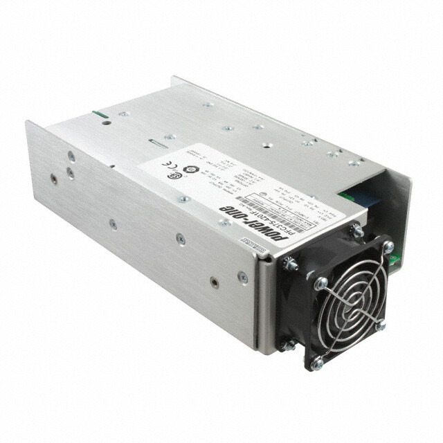
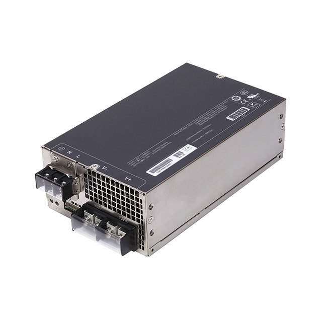
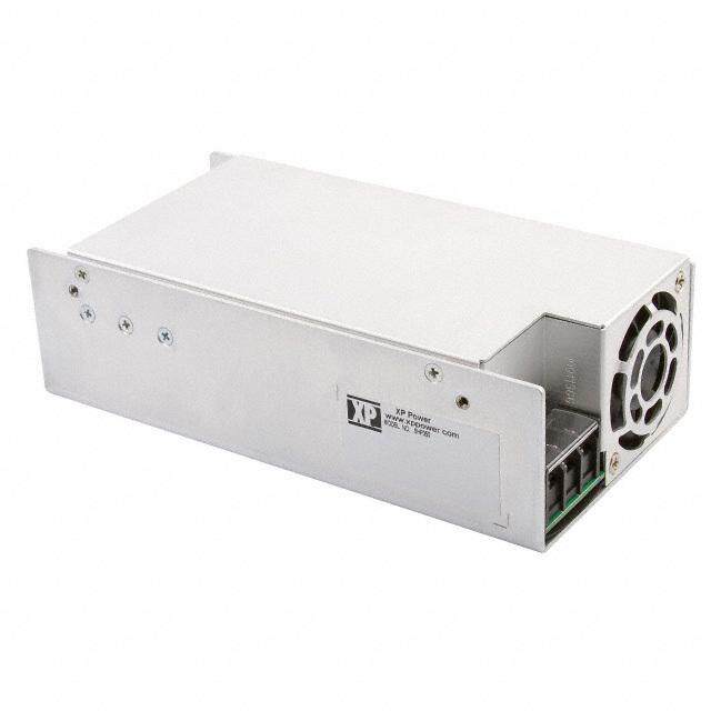
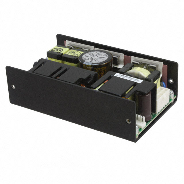
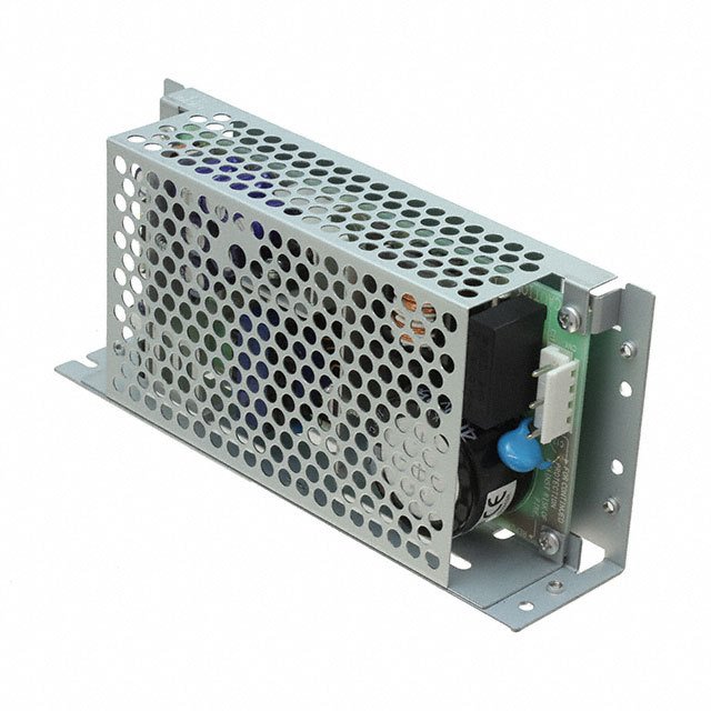
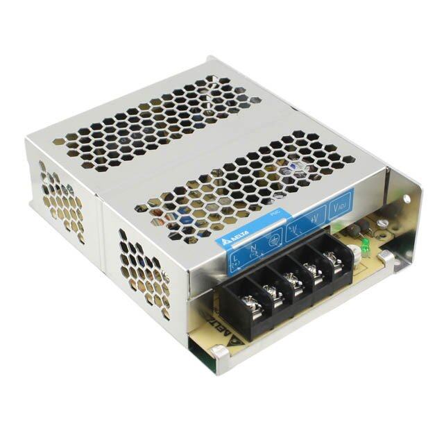
ICGOO电子元器件商城为您提供PFC375-4201F由Power-One设计生产,在icgoo商城现货销售,并且可以通过原厂、代理商等渠道进行代购。 PFC375-4201F价格参考。Power-OnePFC375-4201F封装/规格:AC DC 转换器, 封闭式 AC DC 转换器 4 输出 24V 5V 15V 15V 10A,10A,4A,4A 85 ~ 264 VAC 输入。您可以下载PFC375-4201F参考资料、Datasheet数据手册功能说明书,资料中有PFC375-4201F 详细功能的应用电路图电压和使用方法及教程。
Bel Power Solutions的PFC375-4201F是一款AC-DC转换器,主要应用于需要高效能功率因数校正(PFC)和稳定直流输出的场景。以下是其主要应用场景:

 1. 工业自动化设备
   - PFC375-4201F适用于工业控制设备,如PLC、传感器、伺服驱动器等。它提供稳定的直流电源,支持设备长时间运行。
   - 在工厂自动化系统中,该转换器可以为各种电子组件供电,确保系统高效、可靠地工作。

 2. 通信设备
   - 用于基站、路由器、交换机等通信设备中,为其内部电路提供稳定的直流电源。
   - 高效的功率因数校正功能有助于降低能源损耗,满足通信设备对高效率和低发热的要求。

 3. 医疗设备
   - 可应用于诊断设备、监护仪、超声波设备等医疗仪器中。其高可靠性设计能够确保医疗设备在关键任务中的稳定运行。
   - 符合严格的医疗行业标准,提供安全隔离和低电磁干扰(EMI)性能。

 4. 测试与测量仪器
   - 用于示波器、信号发生器、频谱分析仪等精密测试设备中,提供精确且稳定的电源支持。
   - 其高效的PFC功能减少了电网波动对测试结果的影响。

 5. LED照明系统
   - 在大功率LED照明应用中,PFC375-4201F可作为驱动电源,提供恒定电流以确保LED灯的亮度一致性和长寿命。
   - 高效的功率因数校正有助于减少能源浪费,并满足现代绿色照明的需求。

 6. 电动汽车充电站
   - 用于中小型电动汽车充电桩中,为充电模块提供可靠的直流电源。
   - 具备良好的散热性能和抗干扰能力,适应户外复杂环境。

 7. 数据中心与服务器
   - 为服务器、存储设备和其他IT基础设施提供高效电源支持。
   - 其紧凑的设计和高效率特性使其非常适合空间有限的数据中心环境。

 总结
PFC375-4201F凭借其高效能、高可靠性和宽输入电压范围,广泛应用于工业、通信、医疗、测试测量、LED照明、电动汽车充电以及数据中心等领域。它的功率因数校正功能显著提升了能源利用率,同时降低了运营成本,是现代电子设备的理想电源解决方案。
| 参数 | 数值 |
| 产品目录 | |
| 描述 | AC/DC CNVRTR 24V 5V 2X15V 375W |
| 产品分类 | |
| 品牌 | Bel Power Solutions |
| 数据手册 | |
| 产品图片 |
|
| 产品型号 | PFC375-4201F |
| rohs | 含铅 / 不符合限制有害物质指令(RoHS)规范要求 |
| 产品系列 | PFC375 |
| 其它名称 | PFC375-4201F-ND |
| 功率(W) | 375W |
| 功率(W)-最大值 | 375W |
| 大小/尺寸 | 9.00" 长 x 5.00" 宽 x 2.50" 高(228.6mm x 127.0mm x 63.5mm) |
| 安装类型 | 底座安装 |
| 工作温度 | 0°C ~ 50°C |
| 应用 | ITE(商业) |
| 所需最小负载 | 是 |
| 效率 | 68% |
| 标准包装 | 5 |
| 特性 | 可调输出,负载均分,PFC,遥测,通用输入 |
| 电压-输入 | 85 ~ 264 VAC |
| 电压-输出1 | 24V |
| 电压-输出2 | 5V |
| 电压-输出3 | 15V |
| 电压-输出4 | 15V |
| 电压-隔离 | 2.6kV (2600V) |
| 电流-输出(最大值) | 10A, 10A, 4A, 4A |
| 相关产品 | /product-detail/zh/0022011022/WM9141-ND/403288/product-detail/zh/0022011042/WM2022-ND/403290 |
| 类型 | 封闭式 |
| 认可 | CE |
| 输出数 | 4 |


- 商务部:美国ITC正式对集成电路等产品启动337调查
- 曝三星4nm工艺存在良率问题 高通将骁龙8 Gen1或转产台积电
- 太阳诱电将投资9.5亿元在常州建新厂生产MLCC 预计2023年完工
- 英特尔发布欧洲新工厂建设计划 深化IDM 2.0 战略
- 台积电先进制程称霸业界 有大客户加持明年业绩稳了
- 达到5530亿美元!SIA预计今年全球半导体销售额将创下新高
- 英特尔拟将自动驾驶子公司Mobileye上市 估值或超500亿美元
- 三星加码芯片和SET,合并消费电子和移动部门,撤换高东真等 CEO
- 三星电子宣布重大人事变动 还合并消费电子和移动部门
- 海关总署:前11个月进口集成电路产品价值2.52万亿元 增长14.8%

PDF Datasheet 数据手册内容提取
The PFC375 products of the PerFormanCe Power Series incorporate high performance midrange power, active Power Factor Correction (PFC), and high reliability to meet varied commercial and industrial requirements. Providing tightly-regulated DC power in a wide variety of single and multiple output configurations, the PFC375 is designed to provide full output power with only 300 Linear Feet per Minute (LFM) forced-air cooling (factory installed fan optional). Other features include remote sense, power fail, logic level inhibit, and DC power good. Main channel current sharing is provided for redundant applications. The PFC375 is available with SAE mountings or optional metric mountings. The PFC375 product line is approved to the latest international regulatory standards and displays the CE Mark. RoHS Compliant Greater than 1 million hours demonstrated MTBF Power Factor Correction (PFC) meets EN61000-3-2 Fully-regulated outputs Main output remote sense Current Share, Power Fail, and Power Good signals Overtemperature, overvoltage, and overcurrent protected Available with metric and SAE mountings Input transient & ESD compliance to EN61000-4-2/-3/-4/-5 Fan output voltage and optional fan Asia-Pacific Europe, Middle East North America +86 755 298 85888 +353 61 225 977 +1 866 513 2839 © 2015 Bel Power Solutions, Inc. BCD.00594_AB
2 OUTPUT ADJUSTMENT MAX. OUTPUT LINE LOAD RIPPLE & INITIAL SETTING MODEL VOLTAGE RANGE CURRENT 1 REGULATION REGULATION NOISE % p-p 2 ACCURACY PFC375-1012G 12V 10.8V to 13.5V 30A 0.2% 0.8% 1% 11.94V to 12.06V PFC375-1015G 15V 12.0V to 17.0V 25A 0.2% 0.6% 1% 14.94V to 15.06V PFC375-1024G 24V 21.6V to 26.4V 15A 0.5% 0.8% 1% 23.88V to 24.12V PFC375-1028G 28V 25.2V to 30.8V 13.4A 0.5% 0.9% 0.9% 27.86V to 28.14V PFC375-1048FG 48V 46.0V to 56.0V 7.8A 0.5% 1.0% 1% 47.52V to 48.48V NOTES: 1 Output currents ratings are expressed with 300 LFM forced air. 2 Maximum peak-to-peak noise expressed as a percentage of output voltage, 20 MHz bandwidth. 3 Models without suffix G use the lead solder exemption Ooo Model numbers highlighted in yellow are not recommended for new designs or EOL. Isolated V3 and V4 Can Be Used as Positive Or Negative Output OUTPUT ADJUSTMENT OUTPUT PEAK OUTPUT LINE LOAD RIPPLE & INITIAL SETTING MODEL VOLTAGE RANGE CURRENT1 CURRENT3 REGULATION REGULATION NOISE % p-p2 ACCURACY +5V 4.5V to 5.5V 3.5 - 40A 40A 0.4% 0.8% 1% 4.98V to 5.02V +12V 11.3V to 12.6V 10A 16A 0.9% 0.9% 1% 11.9V to 12.1V PFC375-4000G 12V 11.3V to 12.6V 6A 6A 0.9% 0.9% 1% 11.9V to 12.1V 5V Fixed 3A 3A 2% 2% 2.4% 4.9V to 5.1V +5V 4.5V to 5.5V 3.5 - 40A 40A 0.4% 0.8% 1% 4.98V to 5.02V +12V 11.3V to 12.6V 10A 16A 0.9% 0.9% 1% 11.9V to 12.1V PFC375-4001G4 12V 11.3V to 12.6V 6A 6A 0.9% 0.9% 1% 11.9V to 12.1V 12V 11.0V to 15.8V 3A 3A 0.9% 0.9% 1% 11.9V to 12.1V +5V 4.5V to 5.5V 3.5 - 40A 40A 0.4% 0.8% 1% 4.98V to 5.02V +12V 11.3V to 12.6V 10A 16A 0.9% 0.9% 1% 11.9V to 12.1V PFC375-4002G5 12V 11.3V to 12.6V 6A 6A 0.9% 0.9% 1% 11.9V to 12.1V 24V 22.0V to 28.0V 3A 3A 0.5% 0.8% 1% 23.8V to 24.2V +5V 4.5V to 5.5V 3.5 - 40A 40A 0.4% 0.8% 1% 4.98V to 5.02V +12V 11.3V to 12.6V 10A 16A 0.9% 0.9% 1% 11.9V to 12.1V PFC375-4004G 15V 14.2V to 15.8V 4A 4A 0.7% 0.7% 1% 14.9V to 15.1V 15V 14.2V to 15.8V 4A 4A 0.7% 0.7% 1% 14.9V to 15.1V +5V 4.5V to 5.5V 3.5 - 40A 40A 0.4% 0.8% 1% 4.98V to 5.02V +12V 11.3V to 12.6V 10A 16A 0.9% 0.9% 1% 11.9V to 12.1V PFC375-4005G6 24V 22.0V to 28.0V 3A 3A 0.5% 0.8% 1% 23.8V to 24.2V 24V 22.0V to 28.0V 3A 3A 0.5% 0.8% 1% 23.8V to 24.2V +24V 21.5V to 26.4V 1 - 10A 10A 0.5% 0.8% 1% 23.8V to 24.2V +5V 4.5V to 5.5V 10A 16A 0.4% 0.8% 1% 4.98V to 5.02V PFC375-4200G 12V 11.4V to 12.6V 4A 4A 0.5% 1% 1% 11.9V to 12.1V 12V 11.4V to 12.6V 4A 4A 0.5% 1% 1% 11.9V to 12.1V tech.support@psbel.com
3 +24V 21.5V to 26.4V 1 - 10A 10A 0.5% 0.8% 1% 23.8V to 24.2V +5V 4.5V to 5.5V 10A 16A 0.4% 0.8% 1% 4.98V to 5.02V PFC375-4201G 15V 14.2V to 16.0V 4A 4A 0.5% 0.8% 1% 14.9V to 15.1V 15V 13.7V to 16.0V 4A 4A 0.5% 0.8% 1% 14.9V to 15.1V +5V 4.5V to 5.5V 3.5 - 50A 50A 0.4% 0.8% 1% 4.98V to 5.02V +12V 11.3V to 12.6V 10A 16A 0.9% 0.9% 1% 11.9V to 12.1V PFC375-4500G 12V 11.3V to 12.6V 6A 6A 0.9% 0.9% 1% 11.9V to 12.1V 5V 4.5V to 5.5V 3A 3A 2% 0.9% 1% 4.9V to 5.1V NOTES: 1 Output currents ratings are expressed with 300 LFM forced air. 2 Maximum peak-to-peak noise expressed as a percentage of output voltage, 20 MHz bandwidth. 3 Peak loads up to 450 Watts for 60 seconds or less are acceptable, (10% duty cycle max.). Peak power must not exceed 450 Watts. 4 V4 can be adjusted to 16 V with a minimum load of 5 A on V1. 5 For operation of V4 greater than 24 V, consult factory. 6 V3 and V4 may be series connected to obtain 48 V. 7 Models without suffix G use the lead solder exemption Ooo Model numbers highlighted in yellow are not recommended for new designs or EOL PARAMETER CONDITIONS / DESCRIPTION MIN NOM MAX UNITS Input Voltage - AC Continuous input range. 85 264 VAC Input Frequency AC Input. 47 63 Hz Lowest AC input voltage that regulation is maintained with full rated Brown Out Protection 85 VAC loads. Hold-Up Time Over full AC input voltage range at full rated load. 20 ms Input Current 85 VAC at full rated load. 6 ARMS Non-user serviceable internally located AC input line fuse, F10A, Input Protection 250V. 110 VAC 35 Inrush Surge Current Internally limited by thermistor, one cycle, 25°C. 220 VAC 65 APK Power Factor Per EN61000-3-2. 0.98 W/VA Operating Frequency Switching frequency of main transformer. 100 kHz PARAMETER CONDITIONS / DESCRIPTION MIN NOM MAX UNITS Full rated load, 110 VAC. Varies with distribution of loads among Efficiency 68 % outputs. Single output models. 0 Minimum Loads Multiple output models, 5V main output only. 3.5 Amps Multiple output models, 24V main output only. 1 Ripple and Noise Full load, 20MHz bandwidth. See Model Selection Charts 300 LFM forced air cooling required for operation. See optional fan. Output Power Continuous power, multiple output models. 375 Watts Peak power, all models. 450 Overshoot / Undershoot Output voltage overshoot/undershoot at turn-on. 0 V Varies by output. Total regulation includes: line changes from 85- Regulation 132 VAC or 170-264 VAC, changes in load starting at 20% load See Model Selection Charts and changing to 100% load. tech.support@psbel.com
4 Recovery time, to within 1% of initial set point due to a 50-100% Transient Response load change, 3% max. deviation. (Main output only on multi-output 1 ms units). Turn-On Delay Time required for initial output voltage stabilization. 1 Sec Turn-On Rise Time Time required for output voltage to rise from 10% to 90%. 10 ms PARAMETER CONDITIONS / DESCRIPTION MIN NOM MAX UNITS Provided on single output units and the main output only of multiple output units. PFC375-30XXG, PFC375-40XXG, PFC375-45XXG 6.0 6.4 PFC375-1012G 13.5 15.5 Overvoltage Protection PFC375-1015G 17.0 19.5 V PFC375-1024G 27.0 30.7 PFC375-1028G 30.8 35.0 PFC375-1048G 60.0 70.0 PFC375-42XXG 27.0 30.7 Fully protected against output overload and short circuit. Automatic Overload Protection recovery upon removal of overload condition. Overtemperature System shutdown due to excessive internal temperature, automatic reset. Protection Total voltage compensation for cable losses with respect to the main Remote Sense 250 mV output. Current Share Accuracy of shared current with up to 6 parallel units. 10 % TTL compatible logic signal will inhibit outputs by the application Inhibit of a logic low signal. An open circuit or external TTL high signal allows normal operation. Input Power TTL compatible logic signal. Time before regulation dropout due to 5 ms Fail Warning 5 loss of input power at 110 VAC. TTL compatible signal. Signal is low if main output is greater or less than Power Good 10% of nominal. Provides 170 mA current to user-supplied fan, if fan option is not Fan Voltage 12 V selected. PARAMETER CONDITIONS / DESCRIPTION MIN NOM MAX UNITS Approved to the latest edition of the following standards. Agency Approvals Approved UL/CSA60950-1, EN60950-1 and IEC60950-1 Dielectric Withstand Input to Output per EN60950. 2600 VDC Voltage Electromagnetic FCC CFR title 47 Part 15 Sub-Part B - Conducted. B Class Interference EN55022 / CISPR 22 Conducted. B ESD Susceptibility Per EN61000-4-2, level 4. 8 kV Radiated Susceptibility Per EN61000-4-3, level 3. 10 V/M EFT/Burst Per EN61000-4-4, level 4. ± 4 kV Line-to-Line 1 Input Transient Protection Per EN61000-4-5 level 3. kV Line-to-Ground 2 Insulation Resistance Input-to-Output. 10 M Leakage Current Per EN60950, 264 VAC. 2.0 mA tech.support@psbel.com
5 PARAMETER CONDITIONS / DESCRIPTION MIN NOM MAX UNITS Operating. 10k Altitude ASL Ft. Non-Operating. 40k At 100% load: 0 50 Operating Temperature °C Derate linearly above 50°C by 2.5% per °C. At 50% load: 0 70 Storage Temperature -55 85 °C Forced air cooling of 300 LFM is required if the internal fan option is not specified. Cooling air velocity is measured 1/4" Forced Air Cooling above, at the middle of the chassis. Airflow direction is from the input section to the output section. Temperature Coefficient 0°C to 70°C (after 15 minute warmup). ± 0.02 ± 0.05 %/°C Relative Humidity Non-Condensing. 5 95 %RH Operating: 10±3mS, 3 axis, Halfsine. 20 G 20 Shock G Non-operating: 10±3mS, 3 axis, Halfsine. 40 Operating: 5-32 Hz 0.02 in (DA) Vibration 32-2000 Hz Sinusoidal 1 GRMS Non-operating: 6.15 GRMS PARAMETER CONDITIONS / DESCRIPTION MIN NOM MAX UNITS 228.6 x 127.0 x 63.5 mm Overall Size 9.00 x 5.00 x 2.50 in Dimensions 266.7 mm Overall Length With Fan 10.50 in 1.95 kg Weight 4.3 lb PARAMETER CONDITIONS / DESCRIPTION MIN NOM MAX UNITS Add “M” as a suffix to the model number to order chassis with 228.6 x 127.0 x 63.5 mm Metric Mounting M4 x 0.7 mounting inserts. 9.00 x 5.00 x 2.50 in Add “F” as a suffix to the model number to order integral fan. 266.7 x 127.0 x 63.5 mm Fan (Provides required 300 LFM of forced air cooling). 10.50 x 5.00 x 2.50 in 6-32 Screw Terminal on 0.375" (9.5mm) Centers Bus Bar Main Output, E1 & E2, 10-32 Screw Terminal Chassis: 0.090" (2.3mm) Aluminum Alloy, With Clear Finish TERMINAL BLOCKS have 6-32 (PHILSLOT) screw connections on 0.375" (9.53mm) centers; open space clearance for connections is 0.31" (7.87mm). tech.support@psbel.com
6 Figure 1. Mechanical Drawing PFC375 NUCLEAR AND MEDICAL APPLICATIONS - Products are not designed or intended for use as critical components in life support systems, equipment used in hazardous environments, or nuclear control systems. TECHNICAL REVISIONS - The appearance of products, including safety agency certifications pictured on labels, may change depending on the date manufactured. Specifications are subject to change without notice. tech.support@psbel.com