ICGOO在线商城 > 开发板,套件,编程器 > 评估和演示板和套件 > PACPOWR607-P-EVN
 Datasheet下载
- 型号: PACPOWR607-P-EVN
- 制造商: Lattice
- 库位|库存: xxxx|xxxx
- 要求:
| 数量阶梯 | 香港交货 | 国内含税 |
| +xxxx | $xxxx | ¥xxxx |
查看当月历史价格
查看今年历史价格
PACPOWR607-P-EVN产品简介:
ICGOO电子元器件商城为您提供PACPOWR607-P-EVN由Lattice设计生产,在icgoo商城现货销售,并且可以通过原厂、代理商等渠道进行代购。 PACPOWR607-P-EVN价格参考。LatticePACPOWR607-P-EVN封装/规格:评估和演示板和套件, ispPAC-POWR607 Power Supply Supervisor/Tracker/Sequencer Power Management Evaluation Board。您可以下载PACPOWR607-P-EVN参考资料、Datasheet数据手册功能说明书,资料中有PACPOWR607-P-EVN 详细功能的应用电路图电压和使用方法及教程。
Lattice Semiconductor Corporation的PACPOWR607-P-EVN是一款针对其PowerAssist™系列电源管理FPGA的评估与演示套件,主要用于评估和开发低功耗、高性能的可编程电源管理解决方案。该套件适用于需要高效电源设计的嵌入式系统、工业自动化、通信设备及消费类电子产品。

典型应用场景包括:为FPGA、ASIC或处理器供电的多轨电源管理系统;需要动态电压调节(DVS)和电源时序控制的复杂电路;以及对能效和空间布局有高要求的紧凑型设备。通过该评估板,工程师可以快速验证PowerAssist PAC-607器件在实际应用中的性能,如电源监控、故障保护、热管理与I²C接口控制等。

PACPOWR607-P-EVN提供直观的图形用户界面(GUI),便于配置和调试电源参数,加快产品开发周期。它支持灵活的输入输出电压设置,适用于多种负载条件下的测试与优化,是开发先进电源管理方案的理想平台。
| 参数 | 数值 |
| 产品目录 | 编程器,开发系统半导体 |
| 描述 | POWR607/6AT6 EVALUATION BOARD电源管理IC开发工具 POWR607/6AT6 Evaluation Board |
| 产品分类 | |
| 品牌 | Lattice Semiconductor Corporation |
| 产品手册 | |
| 产品图片 |
|
| 产品系列 | 电源管理IC开发工具,Lattice PACPOWR607-P-EVN- |
| mouser_ship_limit | 该产品可能需要其他文件才能进口到中国。 |
| 数据手册 | |
| 产品型号 | PACPOWR607-P-EVN |
| rohs | 无铅 / 符合限制有害物质指令(RoHS)规范要求 |
| 主要属性 | - |
| 主要用途 | 电源管理,电源监控器/跟踪器/序列发生器 |
| 产品 | Evaluation Boards |
| 产品种类 | 电源管理IC开发工具 |
| 使用的IC/零件 | ispPAC-POWR607 |
| 其它名称 | 220-1875 |
| 商标 | Lattice |
| 嵌入式 | - |
| 工具用于评估 | isp-PAC-POWR607 |
| 所含物品 | 板 |
| 接口类型 | JTAG, Serial |
| 描述/功能 | isp-PAC-POWR607 evaluation board |
| 最大工作温度 | + 85 C |
| 最小工作温度 | - 40 C |
| 标准包装 | 1 |
| 用于 | isp-PAC-POWR607 |
| 类型 | Power Management Specialized |
| 辅助属性 | - |
| 输入电压 | 4.5 V to 9 V |
| 输出电压 | 5.5 V, 10.4 V |


- 商务部:美国ITC正式对集成电路等产品启动337调查
- 曝三星4nm工艺存在良率问题 高通将骁龙8 Gen1或转产台积电
- 太阳诱电将投资9.5亿元在常州建新厂生产MLCC 预计2023年完工
- 英特尔发布欧洲新工厂建设计划 深化IDM 2.0 战略
- 台积电先进制程称霸业界 有大客户加持明年业绩稳了
- 达到5530亿美元!SIA预计今年全球半导体销售额将创下新高
- 英特尔拟将自动驾驶子公司Mobileye上市 估值或超500亿美元
- 三星加码芯片和SET,合并消费电子和移动部门,撤换高东真等 CEO
- 三星电子宣布重大人事变动 还合并消费电子和移动部门
- 海关总署:前11个月进口集成电路产品价值2.52万亿元 增长14.8%

PDF Datasheet 数据手册内容提取
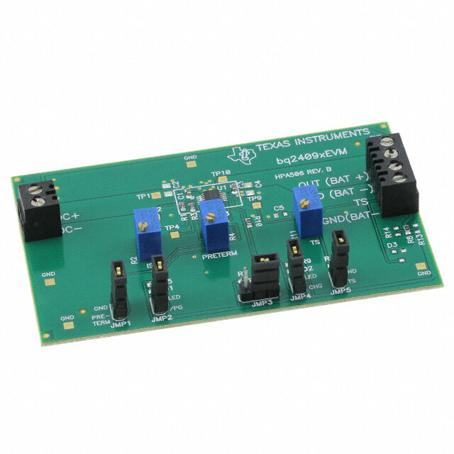
ispPAC-POWR607 Evaluation Board User’s Guide May 2007 Revision: EB28_01.0
ispPAC-POWR607 Lattice Semiconductor Evaluation Board User’s Guide Introduction Lattice Semiconductor’s Power Manager II ispPAC®-POWR607 device simplifies power supply design by integrat- ing the analog and digital functions of power supply management (sequencing, monitoring, reset generation into a single device). This device provides designers with a rich set of features: precision comparators with a built-in volt- age reference, MOSFET drivers and a programmable logic device (PLD) for sequencing and supervisory logic functions or reset control. Configuration for all subsystems in the ispPAC-POWR607 device is stored in non-volatile E2CMOS® memory. Programming is performed via the industry-standard JTAG IEEE 1149.1 interface. PAC-POWR607-EV Evaluation Board The PAC-POWR607-EV evaluation board (Figure 1) allows the designer to quickly configure and evaluate the isp- PAC-POWR607 device on a fully assembled printed-circuit board. The board supports a 32-pin QFN package, pads for user I/O, a JTAG programming cable connector, LEDs and switches. JTAG programming signals can be generated by using an ispDOWNLOAD® programming cable connected between the evaluation board and a PC’s parallel (printer) port. Both analog and digital features of the ispPACPOWR607device can be easily configured using PAC-Designer® software. Figure 1. PAC-POWR607-EV Evaluation Board Programming Interface Lattice Semiconductor’s ispDOWNLOAD cable can be used to program the ispPAC-POWR607 device on the eval- uation board. This cable plugs into a PC-compatible’s parallel port connector, and includes active buffer circuitry inside its DB-25 connector housing. The other end of the ispDOWNLOAD cable terminates in an 8-pin 0.100” pitch header connector, which plugs directly into a mating connector, (J3) provided on the PAC-POWR607-EV evaluation board. Important Note: The board must be un-powered when connecting, disconnecting, or reconnecting the ispDOWN- LOAD Cable. Always connect the ispDOWNLOAD Cable's GND pin (black wire), before connecting any other JTAG pins. Failure to follow these procedures can in result in damage to the ispPAC-POWR607 device and render the board inoperable. 2
ispPAC-POWR607 Lattice Semiconductor Evaluation Board User’s Guide Power Supply Considerations The ispPAC-POWR607 device operates with analog and digital core power supplies of 3.3V, To simplify evaluation work, the evaluation board was designed to operate from a single 4.5V to 9V power supply, which may be brought in through a standard 5mm power plug (J2 - center tip positive). The evaluation board provides a linear regulator to provide the appropriate operating voltages for the ispPACPOWR607 device, as well as reverse polarity protection. The kit comes with a battery and cable that plugs into the connector at J2 and provides power with a 9V battery, see Figure 2. If it is desired to test the current in the power down mode of the ispPAC-POWR607, the link between pins 3 and 4 of J1 should be cut (please refer to Appendix A). Otherwise, approximately 2mA will be drawn when the device is in power down mode. Figure 2. 9V Battery Power Interface Input/Output Connections Connectors are provided for key functions and test points on this evaluation board, as shown In Figure 1. The JTAG programming cable is connected to a header (J3) in the lower right corner of the board. Access to the ispPAC-POWR607 device’s I/O pins is available along the left edge of the assembly, where a 2x17 block of pads (J1)supports the attachment of test probes or a ribbon-cable connector. In addition, there is an array of 70 proto-type holes for interfacing. Two momentary switches, S1 and S2, are provided on the evaluation board. They are connected to IN1_PWRDN and IN2 respectively. Several LEDs are also provided on the evaluation board to indicate proper function and as aids to debugging. LED D2 indicates that the on-board 3.3V supply is powered up. LED D3 is connected to the ispPACPOWR607 device’s TDO line, and will briefly flash when downloading, indicating that download data has made it to the device. Five LEDs are also provided on digital outputs OUT3 through OUT7 so that a user may easily view the progress of Sequence, Monitor, Reset programs run on the evaluation board. Demo Sequence and Reprogramming This evaluation board is shipped from the factory pre-programmed with the “ispPAC_POWR607_LED_Blinker.PAC” sequence from PAC-Designer’s library. The IN1_PWRDN button must be depressed in order t bring the ispPAC- POWR607 device out of its power down mode. The programmed sequence will cause the LEDs to flash for about six seconds, and then the device will revert to the power down mode. In order to reprogram the ispPAC-POWR607, it must be brought out of power down mode. Thus, the IN1_PWRDN button must be depressed immediately before beginning a download to the device from PAC-Designer or ispVM. 3
ispPAC-POWR607 Lattice Semiconductor Evaluation Board User’s Guide Bill of Materials for the ispPAC-POWR607 Evaluation Board Qty. Ref Des Description Dig-Key # or Equivalent 2 C1, C4 10µF 10V Tant. SMD capacitor 478-1751-1-ND 5 C2, C3,C5,C6,C8 0.1µF SMD0603 ceramic capacitor PCC1762CT-ND 1 D1 Diode Schottky 20V 1A SOD123Fl MBR120VLSFT10SCT-ND 1 R1 1k resistor SMD 0805 311-1.0KACT-ND 1 D2 GREEN LED SMD 1206 160-1404-1-ND 6 D3, 4, 5, 6, 7, 8 RED LED SMD 1206 160-1405-1-ND 1 J2 2.5mm power connector CP-102B-ND 1 RN1 Res Net 2k 14-pin SOIC 768-141-R2K-ND 2 R2, R3 10k resistor SMD 0805 311-10KACT-ND 2 R5, R6 4.7k resistor SMD 0805 311-4.7KACT-ND 1 J3 Header 36 pos .100 vert Gold Break into 8-pin used for JTAG WM6736-ND 2 SW1, SW2 Momentary push-button switches P10885SCT-ND 1 U1 ispPAC-POWR607 Lattice Semiconductor 1 U2 IC 3.3V LDO REG SOIC 296-2787-5-ND 1 N/A PCB 2” by 3.5” ispPAC-POWR607 Rev-2 Ordering Information • Part Number: PAC-POWR607-EV References • ispPAC-POWR607 Data Sheet Technical Support Assistance Hotline: 1-800-LATTICE (North America) +1-503-268-8001 (Outside North America) e-mail: isppacs@latticesemi.com Internet: www.latticesemi.com Revision History Date Version Change Summary May 2007 01.0 Initial release. © 2007 Lattice Semiconductor Corp. All Lattice trademarks, registered trademarks, patents, and disclaimers are as listed at www.latticesemi.com/legal. All other brand or product names are trademarks or registered trademarks of their respective holders. The specifications and information herein are subject to change without notice. 4
ispPAC-POWR607 Lattice Semiconductor Evaluation Board User’s Guide Appendix A. Schematics The following figures comprise the schematics for the ispPAC-POWR607 evaluation board. Figure 3 shows the device schematic and JTAG interface, while Figure 4 shows the on-board power-supply circuitry and the LED dis- play. Figure 3. ispPAC-POWR607 Device Schematic D C B A veRvRveRe333 333 ofofof 1 1 111 tehStehSeehSeet draoBdraoBdraoB HVOUT1HVOUT2 IN_OUT3IN_OUT4IN_OUT5IN_OUT6IN_OUT7 R0607R0607R0607 rebrebmmrebm noitalavE 760R noitalavE 760R noitalavE 760Ru0u0u0 2 VCCJ 13 VCCJ 30HVOUT131HVOUT2 OWR0607OWR060727IN/OUT326IN/OUT423IN/OUT522IN/OUT620IN/OUT7 GNDA 11 VCCJ C8C8100n100n TitleTitleTitleispPAC-POWispPAC-POWispPAC-POW uN temucoDziSuN tnemucoDeziSneuN temucoDziSneWOP-CAPpsiAWOP-CAPpsiAWOP-CAPpsiA :etD:etD:etaDaa2 PP VCC 214 CDVCCA ispPAC-ispPAC- GNDD 12 C6C6100n100n VC N1N2N3N4N5N6 U1U1 VMOVMOVMOVMOVMOVMO IN1IN2 TDITDOTMSTCK C5C5100n100n 3 2356710 2928 18141915 C7C750pF50pF VCC 3 N1N2N3N4N5N6 100100 100100 OOOOOO VMVMVMVMVMVM R7R7 R4R4 54 VCC is jumpered to 3.3V at pins 1 and 2 of J1 on the backsideof the board. To measure the device power down current, cut thejumper trace on the backside of the board and connect an ammenterbetween pins 1 and 2. In addition, cut the jumper on the backsidebetweeen pins 3 and 4 of J1 to disconnect VCCJ. Replace with jumperblocks for normal operation.3.3VVCCJ1J1VCCJ 2143IN_OUT765IN_OUT678IN_OUT5109IN_OUT41211IN_OUT31314IN21615IN1_PWRDN1718HVOUT11920IN1_PWRDNHVOUT22122IN2VMON12423VMON2TDI2526VMON3TDO2827VMON4TMS2930TCKVMON53132VMON63433 HEADER 17X2HEADER 17X2 VCC J3J3R5R54.7k4.7k12TDOTDI345TMS67TCK8 R6R6JTAG InterfaceJTAG Interface4.7k4.7k 54 D C B A 5
ispPAC-POWR607 Lattice Semiconductor Evaluation Board User’s Guide Figure 4. Power Supply and LEDs D C B A eevevv3 RRR 333 ofofof 1 1 333 ttteee eee hhh SSS ddd rarara ooo BBB n n n ooo aaaititit uuu 2 N) LEDs D14D14TDOTDO )DER( Power Supply and LEDsPower Supply and LEDsPower Supply and LEDs u mDbNcbNcrebmNtneucoremu tnemuoDremu tnemuoDv OP-v OP-v OP-laE7060RWCAPpsilaE7060RWCAPpsilaE7060RWCAPpsi 2 E D2D2PWRPWR (GRE D13D13OUT7OUT7 )DER( SW3SW3IN2IN2 TitleTitleTitle zizieziSeSeSAAA e:etD:etD:taDaa 4 3 V R1R1 1k1k C4C410u10u10V10V D12D12OUT6OUT6 )DER 3 ( 3. 1 2 V 3 3. 3 3 65 C3C3100n100n 141312111098 R3R310k10k ator 3333 OUTOUT Regul U2U2 TPS777TPS777 NNDbNnGE 12 RN1RN1 1234567 2k X 132k X 13 IN2 3I4I C2C2100n100n D11D11OUT5OUT5 )DER WRDNWRDN ( W4W41_P1_P SSININ 4 C1C110u10u10V10V D10D10OUT4OUT4 E)DR 4 3 4 ( 1 2 pp 3030 T3T3 )D D1D1 MBR1MBR1 D9D9OUOU ER( R2R210k10k KK CC PWR JAPWR JA 123 OUT3OUT4OUT5OUT6OUT7DO WRDN _____T P 5 INININININ N1_ 5 I 22 JJ D C B A 6
Mouser Electronics Authorized Distributor Click to View Pricing, Inventory, Delivery & Lifecycle Information: L attice: PAC-POWR607-EV PACPOWR607-P-EVN