ICGOO在线商城 > PAC500007501FAC000
 Datasheet下载
- 型号: PAC500007501FAC000
- 制造商: Vishay
- 库位|库存: xxxx|xxxx
- 要求:
| 数量阶梯 | 香港交货 | 国内含税 |
| +xxxx | $xxxx | ¥xxxx |
查看当月历史价格
查看今年历史价格
PAC500007501FAC000产品简介:
ICGOO电子元器件商城为您提供PAC500007501FAC000由Vishay设计生产,在icgoo商城现货销售,并且可以通过原厂、代理商等渠道进行代购。 提供PAC500007501FAC000价格参考以及VishayPAC500007501FAC000封装/规格参数等产品信息。 你可以下载PAC500007501FAC000参考资料、Datasheet数据手册功能说明书, 资料中有PAC500007501FAC000详细功能的应用电路图电压和使用方法及教程。
| 参数 | 数值 |
| 产品目录 | |
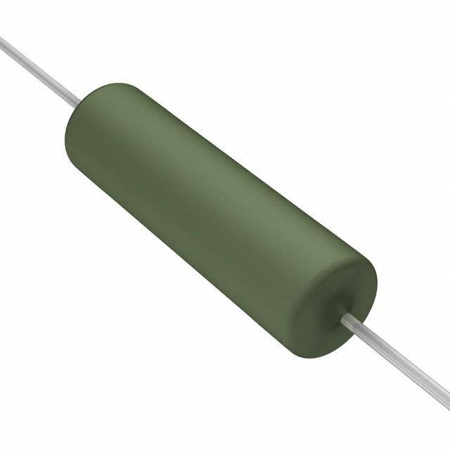
| 描述 | RES 7.5K OHM 5W 1% AXIAL |
| 产品分类 | |
| 品牌 | Vishay BC Components |
| 数据手册 | |
| 产品图片 |
|
| 产品型号 | PAC500007501FAC000 |
| rohs | 无铅 / 符合限制有害物质指令(RoHS)规范要求 |
| 产品系列 | PAC05 |
| 产品目录绘图 |
|
| 供应商器件封装 | 轴向 |
| 其它名称 | 2306 327 37502 |
| 功率(W) | 5W |
| 包装 | 带盒(TB) |
| 大小/尺寸 | 0.295" 直径 x 1.024" 长(7.50mm x 26.00mm) |
| 容差 | ±1% |
| 封装/外壳 | 轴向 |
| 成分 | 绕线 |
| 标准包装 | 500 |
| 温度系数 | ±100ppm/°C |
| 特性 | 耐燃, 脉冲耐受 |
| 电阻(Ω) | 7.5k |
| 端子数 | 2 |
| 高度 | - |


- 商务部:美国ITC正式对集成电路等产品启动337调查
- 曝三星4nm工艺存在良率问题 高通将骁龙8 Gen1或转产台积电
- 太阳诱电将投资9.5亿元在常州建新厂生产MLCC 预计2023年完工
- 英特尔发布欧洲新工厂建设计划 深化IDM 2.0 战略
- 台积电先进制程称霸业界 有大客户加持明年业绩稳了
- 达到5530亿美元!SIA预计今年全球半导体销售额将创下新高
- 英特尔拟将自动驾驶子公司Mobileye上市 估值或超500亿美元
- 三星加码芯片和SET,合并消费电子和移动部门,撤换高东真等 CEO
- 三星电子宣布重大人事变动 还合并消费电子和移动部门
- 海关总署:前11个月进口集成电路产品价值2.52万亿元 增长14.8%


PDF Datasheet 数据手册内容提取
PAC.. Series www.vishay.com Vishay Draloric Cemented Leaded Wirewound Precision Resistors FEATURES • High power dissipation in small volume • Ideal for pulse application • TCR ± 100 ppm/K • Maximum permissible hot spot temperature is 275 °C • Lead (Pb)-free • Tolerance 1 % • Material categorization: for definitions of compliance please see www.vishay.com/doc?99912 The resistor element is a resistive wire which is wound in a The resistor is coated with a green silicon cement which is single layer on a ceramic rod. Metal caps are pressed over not resistant to aggressive fluxes. The coating is the ends of the rod. The ends of the resistance wire and the non-inflammable, will not drip even at high overloads and leads are connected to the caps by welding. Tinned is resistant to most commonly used cleaning solvents, in copper-clad iron leads with poor heat conductivity are accordance with IEC 60 068-2-45. employed permitting the use of relatively short leads to obtain stable mounting without overheating the solder joint. STANDARD ELECTRICAL SPECIFICATIONS POWER RATING LIMITING RESISTANCE RANGE (2) TOLERANCE MODEL P VOLTAGE 25 °C ± % W U max. PAC01 1 P x R 0.10 to 2.2K 1 PAC02 (1) 2 P x R 0.10 to 3.6K 1 PAC03 3 P x R 0.10 to 4.7K 1 PAC04 4 P x R 0.10 to 8.2K 1 PAC05 5 P x R 0.10 to 12K 1 PAC06 6 P x R 0.10 to 12K 1 Notes • For Pulse Diagrams see AC.. Series (www.vishay.com/doc?28730) (1) PAC02 WSZ: P = 1.8 W 25 °C (2) Resistance value to be selected for ± 1 % tolerance from E24 and E96 Revision: 14-Mar-17 1 Document Number: 28731 For technical questions, contact: ww1resistors@vishay.com THIS DOCUMENT IS SUBJECT TO CHANGE WITHOUT NOTICE. THE PRODUCTS DESCRIBED HEREIN AND THIS DOCUMENT ARE SUBJECT TO SPECIFIC DISCLAIMERS, SET FORTH AT www.vishay.com/doc?91000
PAC.. Series www.vishay.com Vishay Draloric PART NUMBER AND PRODUCT DESCRIPTION Part Number: PAC300004701FAC000 P A C 3 0 0 0 0 4 7 0 1 F A C 0 0 0 TOLERANCE PACKAGING MODEL VARIANT TCR/MATERIAL VALUE SPECIAL CODE CODE PAC100 = PAC01 0 = neutral 0 = standard 3 digit value F = ± 1.0 % (see The 3 digits are PAC200 = PAC02 1 = SWI = (± 100 ppm/K) 1 digit multiplier Packaging used for all special PAC300 = PAC03 Special winding (1) MULTIPLIER table) part styles. PAC400 = PAC04 2 = RT 7 = *10-3 To encode the PAC500 = PAC05 3 = DK SP 20 mm 8 = *10-2 non standard PAC600 = PAC06 4 = DK LP 33 mm (2) 9 = *10-1 specifications all 5 = DK LP 17.8 mm (2) 0 = *100 special parts of one 7 = DK LP 25.4 mm (2) 1 = *101 series are listed in a 8 = DK SP 25.4 mm 2 = *102 cross reference 9 = WSZ 6720 3 = *103 table. C = E/K 25.4 mm (2) 4 = *104 000 = standard Z = value overflow 5 = *105 (special) Product Description: PAC03 4K7 1 % AC PAC03 4K7 1 % AC PACKAGING MODEL (3) VALUE (3) TOLERANCE CODE (3) DESCRIPTION (4) Notes (1) Special winding on request (2) Other dimensions on request (3) See “Part Number and Product Description” (4) See “Packaging Table” PACKAGING TABLE AMMO LOOSE BLISTER MODEL PACK PACK. PACK PACK. PACK PACK. PIECES PIECES PIECES CODE DESC. CODE DESC. CODE DESC. PAC01 1000 A1 A1 PAC01 DK/EK 500 LC LC PAC01RT 2500 AE AE PAC02 500 AC AC PAC02 DK/EK 500 LC LC PAC02 WSZ 1250 BM BM PAC03 500 AC AC PAC03 DK/EK 500 LC LC PAC04 500 AC AC PAC04 DK/EK 500 LC LC PAC05 500 AC AC PAC05 DK/EK 250 LB LB PAC06 500 AC AC PAC06 DK/EK 250 LB LB Revision: 14-Mar-17 2 Document Number: 28731 For technical questions, contact: ww1resistors@vishay.com THIS DOCUMENT IS SUBJECT TO CHANGE WITHOUT NOTICE. THE PRODUCTS DESCRIBED HEREIN AND THIS DOCUMENT ARE SUBJECT TO SPECIFIC DISCLAIMERS, SET FORTH AT www.vishay.com/doc?91000
PAC.. Series www.vishay.com Vishay Draloric DIMENSIONS in millimeters [inches] G D L x (Lacquer) d WEIGHT g MODEL D L d X G max. max. max. PER UNIT PAC01 4.3 [0.169] 11 [0.433] 2 63 ± 1 [2.480 ± 0.039] 0.52 PAC02 4.8 [0.189] 13 [0.512] 2 63 ± 1 [2.480 ± 0.039] 0.75 PAC03 5.5 [0.217] 16.5 [0.650] 3 63 ± 1 [2.480 ± 0.039] 1.10 0.8 ± 0.03 [0.031 ± 0.001] PAC04 7.5 [0.295] 18 [0.709] 3 73 ± 1 [2.874 ± 0.039] 1.90 PAC05 7.5 [0.295] 26 [1.024] 3 73 ± 1 [2.874 ± 0.039] 2.60 PAC06 7.5 [0.295] 26 [1.024] 3 73 ± 1 [2.874 ± 0.039] 2.60 Note • For packaging dimensions see: www.vishay.com/doc?28721 Revision: 14-Mar-17 3 Document Number: 28731 For technical questions, contact: ww1resistors@vishay.com THIS DOCUMENT IS SUBJECT TO CHANGE WITHOUT NOTICE. THE PRODUCTS DESCRIBED HEREIN AND THIS DOCUMENT ARE SUBJECT TO SPECIFIC DISCLAIMERS, SET FORTH AT www.vishay.com/doc?91000
PAC.. Series www.vishay.com Vishay Draloric BENDING FORMS L Ø D KINK TYPE S = EK h Ø d S P TYPE Ø d Ø D L h ± 1 P ± 1 S max. max. PAC01 17.8 PAC02 - PAC04 0.8 (1) (1) 8 25.4 2 PAC05 - PAC06 33.0 P Ø D 1 L DOUBLE KINK SP = DK SP h Ø d c S P Ø B 2 TYPE Ø D Ø D L h ± 1 P ± 1 P ± 3 S Ø B c max. 1 2 max. PAC01 19.8 17.8 22.0 20.0 PAC02 - PAC04 0.8 (1) (1) 8 2 1.0 ± 0.1 4.5 ± 1 27.4 25.4 PAC05 - PAC06 35.0 33.0 P Ø D 1 L DOUBLE KINK LP = DK LP h Ø d c S P Ø B 2 TYPE Ø D Ø D L h ± 1 P ± 1 P ± 3 S Ø B c max. 1 2 max. PAC01 - PAC02 17.8 17.8 PAC02 - PAC04 0.8 (1) (1) 8 25.4 25.4 2 1.0 ± 0.1 4.5 ± 1 PAC05 - PAC06 33.0 33.0 Note (1) See table DIMENSIONS Revision: 14-Mar-17 4 Document Number: 28731 For technical questions, contact: ww1resistors@vishay.com THIS DOCUMENT IS SUBJECT TO CHANGE WITHOUT NOTICE. THE PRODUCTS DESCRIBED HEREIN AND THIS DOCUMENT ARE SUBJECT TO SPECIFIC DISCLAIMERS, SET FORTH AT www.vishay.com/doc?91000
PAC.. Series www.vishay.com Vishay Draloric BENDING FORMS A L a Ø D I WSZ H b F E Solder pad dimensions Ø d TYPE Ø d Ø D A L F H E a b l max. PAC02 WSZ 0.8 (1) 17 ± 0.5 11 - 12 4.8 ± 0.5 3.6 ± 0.5 5.0 ± 0.5 2.5 5.5 14.5 Δh P P 1 2 L Ø D H 1 max. 1 W RADIAL TAPED = RT d 2 H H0 t L1 P1 F W W1 0 W P D 0 0 Direction of Unreeling TYPE PAC01 Lead Ø Ø d 0.8 Diameter Ø D (1) Length L (1) Pitch of components P 12.7 ± 1.0 Pitch of spocket holes (2) P 12.7 ± 0.3 0 Distance between hole center and resistor center P 3.85 ± 0.7 1 Distance between hole center and lead center P 6.35 ± 1.0 2 Lead spacing F 5.0 + 0.6, - 0.1 Angle of insertion h1 2 max. Width of carrier tape W 18.0 ± 0.5 Width of adhesive tape W 12.0 ± 0.5 0 Position of holes W 9.0 ± 0.5 1 Position of adhesive tape W 0.5 max. 2 Body to hole center H 19.5 ± 1.0 Lead crimp to hole center (3) H 16.0 ± 0.5 0 Hole Ø D 4.0 ± 0.2 0 Thickness of tape (4) t 0.9 max. Height for cutting L 11 max. 1 Height for insertion H 32 max. 1 Notes (1) See table DIMENSIONS (2) Test over 10 holes - 9 intervals P 12.7 x 9 = 114.3 ± 0.5 0 (3) Parallelism, < 0.5 mm (4) Thickness of carrier tape: 0.55 mm ± 0.1 Revision: 14-Mar-17 5 Document Number: 28731 For technical questions, contact: ww1resistors@vishay.com THIS DOCUMENT IS SUBJECT TO CHANGE WITHOUT NOTICE. THE PRODUCTS DESCRIBED HEREIN AND THIS DOCUMENT ARE SUBJECT TO SPECIFIC DISCLAIMERS, SET FORTH AT www.vishay.com/doc?91000
PAC.. Series www.vishay.com Vishay Draloric DERATING %100 N R I E 80 W O P D 60 E T A R 40 20 0 0 25 50 100 150 200 250 300 AMBIENT TEMPERATURE IN °C Maximum dissipation (P ) as a function max. of the ambient temperature (T ) amb PERFORMANCE TEST PERMISSIBLE CHANGE Climatic category (LCT/UCT/Days) 55/200/56 Climatic Sequence R = ± (0.5 % R + 0.05 ) IEC 60115-1 4.23 Damp Heat, Steady State, IEC 60115-1, 4.24 R = ± (1.0 % R + 0.05 ) (40 ± 2) °C, 56 days, (93 ± 3) % RH Endurance at room temperature (116 % P70), 1000 h, R = ± (0.5 % R + 0.05 ) IEC 60115-1, 4.25.2 Storage, UCT, IEC 60115-1, 4.25.3 R = ± (1.0 % R + 0.05 ) 1000 h, 200 °C, no load Resistance to Soldering Heat, IEC 60115-1, 4.18 R = ± (0.2 % R + 0.05 ) (260 ± 5) °C, (10 ± 1) s Robustness of Termination, IEC 60115-1, 4.16 R = ± (0.1 % R + 0.05 ) 10N Short Time Overload, IEC 60115-1, 4.13 R = ± (0.2 % R + 0.05 ) 10 x Rated Power for 5 s Revision: 14-Mar-17 6 Document Number: 28731 For technical questions, contact: ww1resistors@vishay.com THIS DOCUMENT IS SUBJECT TO CHANGE WITHOUT NOTICE. THE PRODUCTS DESCRIBED HEREIN AND THIS DOCUMENT ARE SUBJECT TO SPECIFIC DISCLAIMERS, SET FORTH AT www.vishay.com/doc?91000
PAC.. Series www.vishay.com Vishay Draloric HISTORICAL 12NC INFORMATION • The resistors had a 12-digit ordering code staring with Resistance Decade 2306 327 RESISTANCE DECADE LAST DIGIT • The subsequent first digit indicated the resistor type and packaging. 0.10 to 0.976 7 • The remaining 4 digits indicated the resistance value: 1 to 9.76 8 - The first 3 digits indicated the resistance value. 10 to 97.6 9 - The last digit indicated the resistance decade in 100 to 976 1 accordance with Resistance Decade table. 1 to 9.76 k 2 10 to 12 k 3 Ordering Example The ordering code for an PAC02, resistor value 47 with ± 1 % tolerance, supplied in ammopack of 500 units was: 2306 327 04709. HISTORICAL 12NC - Resistor type and packaging 2306 327 ..... BANDOLIER IN AMMOPACK TYPE RADIAL STRAIGHT LEADS 2500 units 500 units 1 000 units PAC01 RT (1) - 327 5.... PAC02 - 327 0.... - PAC03 - 327 1.... - PAC04 - 327 2.... - PAC05 - 327 3.... - PAC06 - 327 4.... - Note (1) Radial parts with tin plated copper leads Revision: 14-Mar-17 7 Document Number: 28731 For technical questions, contact: ww1resistors@vishay.com THIS DOCUMENT IS SUBJECT TO CHANGE WITHOUT NOTICE. THE PRODUCTS DESCRIBED HEREIN AND THIS DOCUMENT ARE SUBJECT TO SPECIFIC DISCLAIMERS, SET FORTH AT www.vishay.com/doc?91000
Legal Disclaimer Notice www.vishay.com Vishay Disclaimer ALL PRODUCT, PRODUCT SPECIFICATIONS AND DATA ARE SUBJECT TO CHANGE WITHOUT NOTICE TO IMPROV E RELIABILITY, FUNCTION OR DESIGN OR OTHERWISE. Vishay Intertechnology, Inc., its affiliates, agents, and employees, and all persons acting on its or their behalf (collectively, “Vishay”), disclaim any and all liability for any errors, inaccuracies or incompleteness contained in any datasheet or in any other disclosure relating to any product. Vishay makes no warranty, representation or guarantee regarding the suitability of the products for any particular purpose o r the continuing production of any product. To the maximum extent permitted by applicable law, Vishay disclaims (i) any and all liability arising out of the application or use of any product, (ii) any and all liability, including without limitation special, consequential or incidental damages, and (iii) any and all implied warranties, including warranties of fitness for particular purpose, non-infringement and merchantability. Statements regarding the suitability of products for certain types of applications are based on Vishay’s knowledge of typical requirements that are often placed on Vishay products in generic applications. Such statements are not binding statements about the suitability of products for a particular application. It is the customer’s responsibility to validate that a particular product with the properties described in the product specification is suitable for use in a particular application. Parameters provided in datasheets and / or specifications may vary in different applications and performance may vary over time. All operating parameters, including typical parameters, must be validated for each customer application by the customer’s technical experts. Product specifications do not expand or otherwise modify Vishay’s terms and conditions of purchase, including but not limited to the warranty expressed therein. Except as expressly indicated in writing, Vishay products are not designed for use in medical, life-saving, or life-sustainin g applications or for any other application in which the failure of the Vishay product could result in personal injury or death. Customers using or selling Vishay products not expressly indicated for use in such applications do so at their own risk . Please contact authorized Vishay personnel to obtain written terms and conditions regarding products designed for such applications. No license, express or implied, by estoppel or otherwise, to any intellectual property rights is granted by this documen t or by any conduct of Vishay. Product names and markings noted herein may be trademarks of their respective owners. © 2019 VISHAY INTERTECHNOLOGY, INC. ALL RIGHTS RESERVED Revision: 01-Jan-2019 1 Document Number: 91000