ICGOO在线商城 > P2703ABL

 Datasheet下载
- 型号: P2703ABL
- 制造商: Littelfuse
- 库位|库存: xxxx|xxxx
- 要求:
| 数量阶梯 | 香港交货 | 国内含税 |
| +xxxx | $xxxx | ¥xxxx |
查看当月历史价格
查看今年历史价格
P2703ABL产品简介:
ICGOO电子元器件商城为您提供P2703ABL由Littelfuse设计生产,在icgoo商城现货销售,并且可以通过原厂、代理商等渠道进行代购。 提供P2703ABL价格参考以及LittelfuseP2703ABL封装/规格参数等产品信息。 你可以下载P2703ABL参考资料、Datasheet数据手册功能说明书, 资料中有P2703ABL详细功能的应用电路图电压和使用方法及教程。
| 参数 | 数值 |
| 产品目录 | |
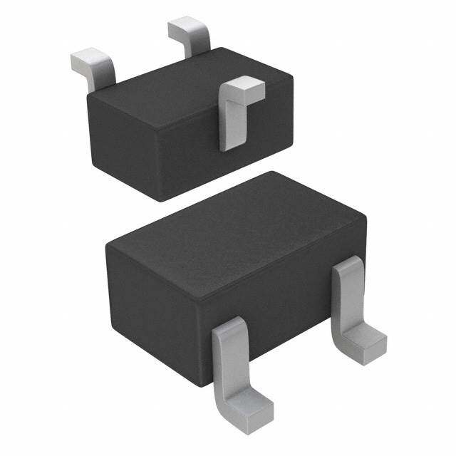
| 描述 | SIDACTOR 3CHP 230V 250A TO-220硅对称二端开关元件 3Chp 230V 100A |
| 产品分类 | |
| 品牌 | Littelfuse Inc |
| 产品手册 | |
| 产品图片 |
|
| rohs | 符合RoHS无铅 / 符合限制有害物质指令(RoHS)规范要求 |
| 产品系列 | 晶体闸流管,硅对称二端开关元件,Littelfuse P2703ABL* |
| 数据手册 | |
| 产品型号 | P2703ABL |
| 不重复通态电流 | 30 A |
| 产品培训模块 | http://www.digikey.cn/PTM/IndividualPTM.page?site=cn&lang=zhs&ptm=23919 |
| 产品目录绘图 |
|
| 产品目录页面 | |
| 产品种类 | 硅对称二端开关元件 |
| 保持电流Ih最大值 | 150 mA |
| 元件数 | 3 |
| 关闭状态漏泄电流(在VDRMIDRM下) | 5 uA |
| 关闭状态电容CO | 10 pF to 50 pF, 20 pF to 75 pF |
| 包装 | 散装 |
| 商标 | Littelfuse |
| 安装风格 | Through Hole |
| 封装 | Bulk |
| 封装/外壳 | TO-220-3(SMT)标片 |
| 封装/箱体 | TO-220-3 |
| 工作结温 | - 40 C to + 150 C |
| 工厂包装数量 | 500 |
| 开启状态电压 | 8 V |
| 最大工作温度 | + 85 C |
| 最大转折电流IBO | 800 mA |
| 最小工作温度 | - 40 C |
| 标准包装 | 500 |
| 电压-导通 | 300V |
| 电压-断态 | 230V |
| 电压-通态 | 8V |
| 电容 | 50pF,75pF |
| 电流-保持(Ih) | 150mA |
| 电流-峰值脉冲(10/1000µs) | 80A |
| 电流-峰值脉冲(8/20µs) | 250A |
| 电流额定值 | 2.2 A |
| 系列 | pxxx3a |
| 转折电流VBO | 300 V |
| 额定重复关闭状态电压VDRM | 230 V |

.jpg)


- 商务部:美国ITC正式对集成电路等产品启动337调查
- 曝三星4nm工艺存在良率问题 高通将骁龙8 Gen1或转产台积电
- 太阳诱电将投资9.5亿元在常州建新厂生产MLCC 预计2023年完工
- 英特尔发布欧洲新工厂建设计划 深化IDM 2.0 战略
- 台积电先进制程称霸业界 有大客户加持明年业绩稳了
- 达到5530亿美元!SIA预计今年全球半导体销售额将创下新高
- 英特尔拟将自动驾驶子公司Mobileye上市 估值或超500亿美元
- 三星加码芯片和SET,合并消费电子和移动部门,撤换高东真等 CEO
- 三星电子宣布重大人事变动 还合并消费电子和移动部门
- 海关总署:前11个月进口集成电路产品价值2.52万亿元 增长14.8%


PDF Datasheet 数据手册内容提取
SIDACtor® Protection Thyristors Baseband Protection (Voice-DS1) SIDACtor® Balanced Series - Modified TO-220 RoHS Pb e3 Description The SIDACtor® Balanced Series are designed to protect baseband equipment from damaging overvoltage transients. The patented “Y” configuration also ensures balanced overvoltage protection that prevents a longitudinal to differential conversion. The series provides a single port through-hole solution that enables voice through DS-1 equipment to comply with various global requlatory standards. Features and Benefits • Low voltage overshoot • Single port protection Agency Approvals • Low on-state voltage • Custom lead forms available • Does not degrade surge Agency Agency File Number capability after multiple • RoHS Compliant and E133083 surge events within limit. Lead-Free • Fails short circuit when • Pb-free E3 means 2nd surged in excess of level interconnect is Pinout Designation ratings Pb-free and the terminal finish material is tin(Sn) • Low capacitance (IPC/JEDEC J-STD- • Balanced overvoltage 609A.01) protection PIN 1 PIN 2PIN 3 Applicable Global Standards Schematic Symbol • TIA-968-A • GR 1089 Intra-building • TIA-968-B • IEC 61000-4-5 2nd 1 3 edition (T) (R) • ITU K.20/21/45 Enhanced Level* • YD/T 1082 • ITU K.20/21/45 Basic • YD/T 993 Level 2 • YD/T 950 (G) • GR 1089 Inter-building* *A/B-rated parts require series resistance Electrical Characteristics V V V V V@I= DRM S DRM S I I I T T @l =5µA @100V/µs @l =5µA @100V/µs H S T 2.2 Amps DRM DRM Part Number Marking Capacitance V min V max V min V max mA mA A V max Pins 1-2, 3-2 Pins 1-3 min max max P1553AALxx P1553AA 130 180 130 180 150 800 2.2 8 P1803AALxx P1803AA 150 210 150 210 150 800 2.2 8 P2103AALxx P2103AA 170 250 170 250 150 800 2.2 8 P2353AALxx P2353AA 200 270 200 270 150 800 2.2 8 P2703AALxx P2703AA 230 300 230 300 150 800 2.2 8 See P3203AALxx P3203AA 270 350 270 350 150 800 2.2 8 Capacitance P3403AALxx P3403AA 300 400 300 400 150 800 2.2 8 Values table P5103AALxx P5103AA 420 600 420 600 150 800 2.2 8 P1553ABLxx P1553AB 130 180 130 180 150 800 2.2 8 P1803ABLxx P1803AB 150 210 150 210 150 800 2.2 8 P2103ABLxx P2103AB 170 250 170 250 150 800 2.2 8 Table continues on next page. © 2017 Littelfuse, Inc. Specifications are subject to change without notice. Revised: 02/23/17
SIDACtor® Protection Thyristors Baseband Protection (Voice-DS1) V V V V V@I= DRM S DRM S I I I T T @l =5µA @100V/µs @l =5µA @100V/µs H S T 2.2 Amps DRM DRM Part Number Marking Capacitance V min V max V min V max mA mA A V max Pins 1-2, 3-2 Pins 1-3 min max max P2353ABLxx P2353AB 200 270 200 270 150 800 2.2 8 P2703ABLxx P2703AB 230 300 230 300 150 800 2.2 8 P3203ABLxx P3203AB 270 350 270 350 150 800 2.2 8 P3403ABLxx P3403AB 300 400 300 400 150 800 2.2 8 P5103ABLxx P5103AB 420 600 420 600 150 800 2.2 8 P1553ACLxx P1553AC 130 180 130 180 150 800 2.2 8 See P1803ACLxx P1803AC 150 210 150 210 150 800 2.2 8 Capacitance P2103ACLxx P2103AC 170 250 170 250 150 800 2.2 8 Values table P2353ACLxx P2353AC 200 270 200 270 150 800 2.2 8 P2703ACLxx P2703AC 230 300 230 300 150 800 2.2 8 P3203ACLxx P3203AC 270 350 270 350 150 800 2.2 8 P3403ACLxx P3403AC 300 400 300 400 150 800 2.2 8 P5103ACLxx P5103AC 420 600 420 600 150 800 2.2 8 Notes: - Absolute maximum ratings measured at T= 25ºC. A - Components are bi-directional. - XX Part Number Suffix: ‘RP’ (Reel Pack), Blank (Bulk Pack), or ‘60’ (Type 60 lead form, Bulk Pack) Capacitance Values pF pF pF pF Pin 1-2 / 3-2 Pin 1-3 Pin 1-2 / 3-2 Pin 1-3 Part Number Part Number Tip-Ground, Ring-Ground Tip-Ring Tip-Ground, Ring-Ground Tip-Ring MIN MAX MIN MAX MIN MAX MIN MAX P1553AALxx 10 45 10 30 P2703ABLxx 20 75 10 50 P1803AALxx 20 40 10 30 P3203ABLxx 20 70 10 45 P2103AALxx 15 35 10 25 P3403ABLxx 15 65 10 45 P2353AALxx 15 35 10 25 P5103ABLxx 15 60 10 40 P2703AALxx 15 35 10 25 P1553ACLxx 30 95 20 60 P3203AALxx 15 30 10 20 P1803ACLxx 30 85 15 55 P3403AALxx 15 30 10 20 P2103ACLxx 30 85 15 55 P5103AALxx 10 60 10 40 P2353ACLxx 25 75 15 50 P1553ABLxx 25 95 15 60 P2703ACLxx 25 75 15 50 P1803ABLxx 25 85 15 55 P3203ACLxx 25 70 15 45 P2103ABLxx 20 85 10 55 P3403ACLxx 20 65 15 45 P2353ABLxx 20 75 15 50 P5103ACLxx 20 60 10 40 Note: Off-state capacitance (C) is measured at 1 MHz with a 2 V bias. O Surge Ratings I PP I di/dt eries 00..52//730100 12 22//1100 12 18.2/2/500 1 2 1100//116600 12 1100//556600 12 59//372200 12 1100//336600 12 1100//11000000 12 150//371000 1 2 50/6TS0M Hz A S A min A min A min A min A min A min A min A min A min A min A/µs max A 20 150 150 90 50 75 75 45 75 20 500 B 25 250 250 150 100 100 125 80 100 25 500 C 50 500 400 200 150 200 175 100 200 50 500 Notes: - Peak pulse current rating (I ) is repetitive and guaranteed for the life of the product. 1 Current waveform in µs - I ratings applicable over tePPmperature range of -40ºC to +85ºC 2 Voltage waveform in µs - TPhPe component must initially be in thermal equilibrium with -40°C < T < +150°C J © 2017 Littelfuse, Inc. Specifications are subject to change without notice. Revised: 02/23/17
SIDACtor® Protection Thyristors Baseband Protection (Voice-DS1) Thermal Considerations Package Symbol Parameter Value Unit Modified T Operating Junction Temperature Range -40 to +150 °C TO-220 J T Storage Temperature Range -65 to +150 °C S PIN 1 PIN 3 R Thermal Resistance: Junction to Ambient 50 °C/W PIN 2 0JA V-I Characteristics t x t Pulse Waveform r d +I PP tr = rise time to peak value %I Peak td = decay time to half value IT – 100 Value IIHS urrent Waveform = tr x td C IDRM se -V +V ul 50 Half Value P VT VDRM ak e VS – P P P I 0 tr td 0 t – Time (µs) -I Normalized V Change vs. Junction Temperature Normalized DC Holding Current vs. Case Temperature S 2.0 14 % 12 C) 1.8 hange – 1068 IHT= 25ºC 11..64 VC S 4 25 °C I(H 1.2 25°C of 2 of 1.0 ercent -40 Ratio 00..86 P -6 -8 0.4 -40 -20 0 20 40 60 80 100 120 140 160 -40 -20 0 20 40 60 80 100120140 160 Junction Temperature (T ) – °C Case Temperature (T ) - ºC J C © 2017 Littelfuse, Inc. Specifications are subject to change without notice. Revised: 02/23/17
SIDACtor® Protection Thyristors Baseband Protection (Voice-DS1) Soldering Parameters Pb-Free assembly Reflow Condition (see Fig. 1) Figure 1 t - Temperature Min (T ) +150°C T P s(min) P Pre Heat - Temperature Max (Ts(max)) +200°C Ramp-up CriTtiLc atol ZToPne - Time (Min to Max) (t) 60-180 secs. s T Average ramp up rate (Liquidus Temp (T) L t L 3°C/sec. Max. eT L to peak) ru S(max) t TS(max) to TL - Ramp-up Rate 3°C/sec. Max. are Ramp-down Reflow - Temperature (TL) (Liquidus) +217°C pmTS(min) Preheat - Temperature (tL) 60-150 secs. eT tS Peak Temp (T) +260(+0/-5)°C P 25 Time within 5°C of actual Peak Temp (tp) 30 secs. Max. time to peak temperature Time (t 25ºC to peak) Ramp-down Rate 6°C/sec. Max. Time 25°C to Peak Temp (T) 8 min. Max. P Do not exceed +260°C Physical Specifications Environmental Specifications 80% Rated V (V Peak) +125°C or +150°C, Lead Material Copper Alloy High Temp Voltage DRM AC 504 or 1008 hrs. MIL-STD-750 (Method 1040) Blocking JEDEC, JESD22-A-101 Terminal Finish 100% Matte-Tin Plated -65°C to +150°C, 15 min. dwell, 10 up to 100 Temp Cycling cycles. MIL-STD-750 (Method 1051) EIA/JEDEC, UL Recognized epoxy meeting JESD22-A104 Body Material flammability classification V-0 Biased Temp & 52 V (+85°C) 85%RH, 504 up to 1008 hrs. EIA/ DC Humidity JEDEC, JESD22-A-101 +150°C 1008 hrs. MIL-STD-750 (Method 1031) High Temp Storage JEDEC, JESD22-A-101 Low Temp Storage -65°C, 1008 hrs. 0°C to +100°C, 5 min. dwell, 10 sec. transfer, Thermal Shock 10 cycles. MIL-STD-750 (Method 1056) JEDEC, JESD22-A-106 Autoclave (Pressure +121°C, 100%RH, 2atm, 24 up to 168 hrs. EIA/ Cooker Test) JEDEC, JESD22-A-102 Resistance to Solder +260°C, 30 secs. MIL-STD-750 (Method 2031) Heat Moisture Sensitivity 85%RH, +85°C, 168 hrs., 3 reflow cycles Level (+260°C Peak). JEDEC-J-STD-020, Level 1 Part Numbering Part Marking P xxx3Ax Lxx XXXXXXXXX Part Marking Code TYPE PACKING STYLE (Refer to Electrical Characteristics Table) P = SIDACtor BRlPa:n Rk:e Belu Plkack xxxxx Date Code MEDIAN VOLTAGE 60: Type 60 Lead Form CO N S TRUCTION (for Type 60 orders, contact factory) VARIABLE RoHS COMPLIANT PACKAGE TYPE IPP RATING © 2017 Littelfuse, Inc. Specifications are subject to change without notice. Revised: 02/23/17
SIDACtor® Protection Thyristors Baseband Protection (Voice-DS1) Dimensions - Modified TO-220 Tape and Reel Specification — Modified TO-220 Inches Millimeters A O 0.240 (6.10) 0.019 Min Max Min Max (0.5) D A 0.400 0.410 10.16 10.42 1.626 0.750 ± 0.010 (41.15) (19.05 ± 0.25) D 0.360 0.375 9.14 9.53 F Temperature 0.720 MeasPuorienmtent F 0.110 0.130 2.80 3.30 (18.29) 0.360 0.500 0.100 0.100 G P G 0.540 0.575 13.71 14.61 (9.14) (12.7) (2.54) (2.54) PPIINN 32 H 0.025 0.035 0.63 0.89 14.173 (360.0) PIN 1 J 0.195 0.205 4.95 5.21 Dimensions are in inches L (and millimeters). K M K 0.095 0.105 2.41 2.67 H N L 0.060 0.075 1.52 1.90 Direction of Feed J M 0.070 0.085 1.78 2.16 1.968 (50.0) The modified TO-220 package is designed to N 0.018 0.024 0.46 0.61 meet mechanical standards as set forth in JEDEC publication number 95. O 0.178 0.188 4.52 4.78 P 0.290 0.310 7.37 7.87 Packing Options Package Packaging Description Added Suffix Industry Standard Type Quantity Modified TO-220 700 RP EIA-468-B Tape and Reel Pack Modified TO-220 N / A 500 EIA-468-B A Bulk Pack (no suffix required) Modified TO-220 60 Type 60 Lead Form 500 (special order item, contact N/A Bulk Pack factory for details) Additional Information Datasheet Resources Samples Disclaimer Notice - Information furnished is believed to be accurate and reliable. However, users should independently evaluate the suitability of and test each product selected for their own applications. Littelfuse products are not designed for, and may not be used in, all applications. Read complete Disclaimer Notice at www.littelfuse.com/disclaimer-electronics. © 2017 Littelfuse, Inc. Specifications are subject to change without notice. Revised: 02/23/17