 Datasheet下载
- 型号: P0720SCMCLRP
- 制造商: Littelfuse
- 库位|库存: xxxx|xxxx
- 要求:
| 数量阶梯 | 香港交货 | 国内含税 |
| +xxxx | $xxxx | ¥xxxx |
查看当月历史价格
查看今年历史价格
P0720SCMCLRP产品简介:
ICGOO电子元器件商城为您提供P0720SCMCLRP由Littelfuse设计生产,在icgoo商城现货销售,并且可以通过原厂、代理商等渠道进行代购。 P0720SCMCLRP价格参考。LittelfuseP0720SCMCLRP封装/规格:TVS - 晶闸管, 。您可以下载P0720SCMCLRP参考资料、Datasheet数据手册功能说明书,资料中有P0720SCMCLRP 详细功能的应用电路图电压和使用方法及教程。
Littelfuse Inc. 是一家知名的电路保护解决方案提供商,其 P0720SCMCLRP 是一款属于 TVS(瞬态电压抑制)类别中的晶闸管(Thyristor)型器件。该器件主要用于高电压、高电流环境下的过压保护。

P0720SCMCLRP 的典型应用场景包括:

1. 通信设备保护:用于保护电信设备和基站免受雷击或静电放电(ESD)引起的高压瞬变损害。

2. 工业控制系统:在工业自动化系统中,用于保护敏感的控制电路和PLC(可编程逻辑控制器)免受瞬态电压干扰。

3. 电源设备:应用于开关电源、不间断电源(UPS)等设备中,作为输入或输出端的过压保护元件。

4. 铁路与交通系统:用于轨道交通设备中,保护电子系统免受因电感负载切换或雷击引起的电压浪涌。

5. 消费类电子产品:如高端家电、变频空调等产品中,用于增强系统的电磁兼容性(EMC)和稳定性。

该器件具有较高的浪涌耐受能力和较低的导通电压,适用于AC/DC电源线、信号线等关键部位的过压保护。采用表面贴装(SMD)封装,适合自动化生产,广泛应用于需要高可靠性设计的电子系统中。
| 参数 | 数值 |
| 产品目录 | |
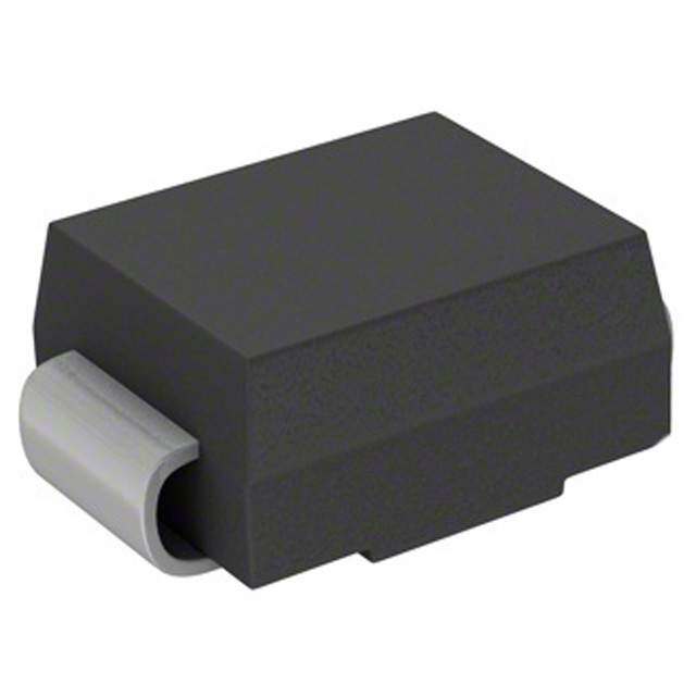
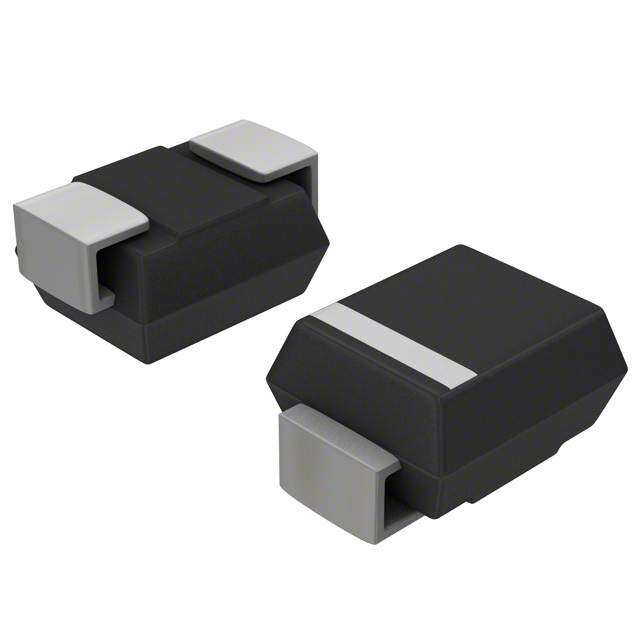
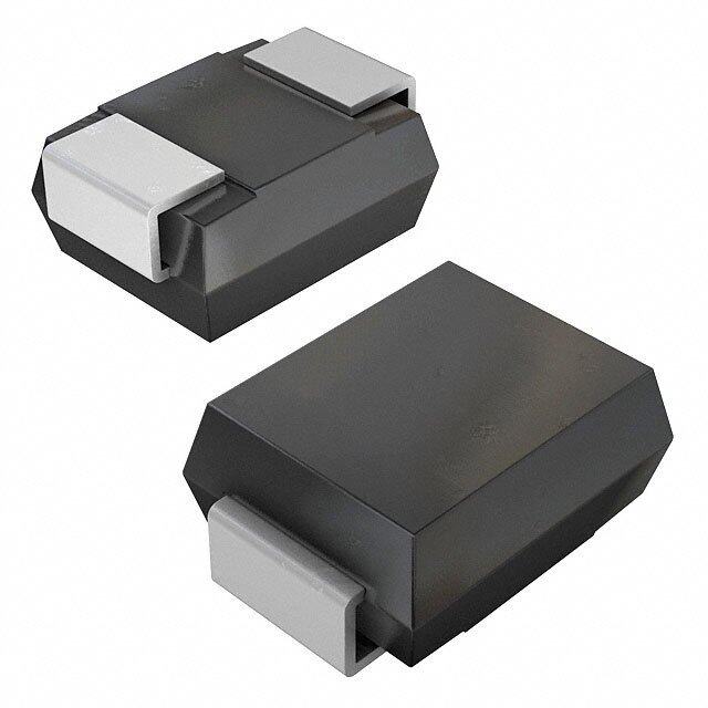
| 描述 | SIDACTOR MC BI 65V 400A DO-214AA |
| 产品分类 | |
| 品牌 | Littelfuse Inc |
| 数据手册 | |
| 产品图片 |
|
| 产品型号 | P0720SCMCLRP |
| rohs | 无铅 / 符合限制有害物质指令(RoHS)规范要求 |
| 产品系列 | SIDACtor® |
| 产品培训模块 | http://www.digikey.cn/PTM/IndividualPTM.page?site=cn&lang=zhs&ptm=23919 |
| 元件数 | 1 |
| 其它名称 | P0720SCMCLRPCT |
| 包装 | 剪切带 (CT) |
| 封装/外壳 | DO-214AA,SMB |
| 标准包装 | 1 |
| 电压-导通 | 88V |
| 电压-断态 | 65V |
| 电压-通态 | 5V |
| 电容 | 75pF |
| 电流-保持(Ih) | 150mA |
| 电流-峰值脉冲(10/1000µs) | 100A |
| 电流-峰值脉冲(8/20µs) | 400A |


PDF Datasheet 数据手册内容提取
SIDACtor® Protection Thyristors Broadband OptimizedTM Protection MC Series - DO-214 RoHS Pb e3 Description The MC Series DO-214 are low capacitance SIDACtor® components designed to protect broadband equipment such as VOIP, DSL modems and DSLAMs from damaging overvoltage transients. The series provides a surface mount solution that enables equipment to comply with global regulatory standards while limiting the impact to broadband signals. Features and Benefits • Low voltage overshoot • RoHS Compliant and Halogen-Free • Low on-state voltage • Pb-free E3 means 2nd level • Does not degrade surge interconnect is Pb-free and capability after multiple the terminal finish material Agency Approvals surge events within limit. is tin(Sn) (IPC/JEDEC J-STD- • 40% lower capacitance 609A.01) Agency Agency File Number than our Baseband • Fails short circuit when E133083 Protectors, for applications surged in excess of ratings that demand greater signal integrity Pinout Designation Applicable Global Standards NOT APPLICABLE • TIA-968-A • GR 1089 Intra-building • TIA-968-B • IEC 61000-4-5 2nd edition Schematic Symbol • ITU K.20/21/45 Enhanced Level* • YD/T 1082 • ITU K.20/21/45 Basic Level • YD/T 993 • GR 1089 Inter-building* • YD/T 950 *A-rated parts require series resistance Electrical Characteristics V V V Capacitance DRM S I I I T @l =5µA @100V/µs H S T @I=2.2 Amps @1MHz, 2V bias Part Number Marking DRM T V min V max mA min mA max A max V max pF min pF max P0080SAMCLRP P-8AM 6 25 50 800 2.2 4 10 35 P0220SAMCLRP P02AM 15 32 50 800 2.2 4 10 35 P0300SAMCLRP P03AM 25 40 50 800 2.2 4 10 35 P0080SCMCLRP P-8CM 6 25 50 800 2.2 4 25 60 P0220SCMCLRP P02CM 15 32 50 800 2.2 4 25 60 P0300SCMCLRP P03CM 25 40 50 800 2.2 4 15 40 P0640SCMCLRP P06CM 58 77 150 800 2.2 4 50 80 P0720SCMCLRP P07CM 65 88 150 800 2.2 4 50 75 P0900SCMCLRP P09CM 75 98 150 800 2.2 4 40 70 P1100SCMCLRP P11CM 90 130 150 800 2.2 4 40 70 P1300SCMCLRP P13CM 120 160 150 800 2.2 4 35 60 P1500SCMCLRP P15CM 140 180 150 800 2.2 4 30 55 P1800SCMCLRP P18CM 170 220 150 800 2.2 4 30 50 P2100SCMCLRP P21CM 180 240 150 800 2.2 4 30 50 P2300SCMCLRP P23CM 190 260 150 800 2.2 4 30 50 P2600SCMCLRP P26CM 220 300 150 800 2.2 4 30 45 P3100SCMCLRP P31CM 275 350 150 800 2.2 4 30 45 P3500SCMCLRP P35CM 320 400 150 800 2.2 4 25 50 P4500SCMCLRP P45CM 400 530 50 800 2.2 4 25 45 Notes: - Absolute maximum ratings measured at T= 25ºC (unless otherwise noted). A - Components are bi-directional. © 2017 Littelfuse, Inc. Specifications are subject to change without notice. Revised: 02/23/17
SIDACtor® Protection Thyristors Broadband OptimizedTM Protection Surge Ratings I eries 00..52//730100 12 22//1100 12 18.2/2/500 1 2 1100//116600 12 1100//55P66P00 12 59//372200 12 1100//336600 12 1100//11000000 12 150//371000 1 2 50/I6TS0M Hz di/dt S A min A min A min A min A min A min A min A min A min A min A/µs max A 20 150 150 90 50 75 75 45 75 25 500 C 50 500 400 200 150 200 175 100 200 3 35 500 Notes: - Peak pulse current rating (I ) is repetitive and guaranteed for the life of the product that remains in thermal equilibrium. PP 1 Current waveform in µs - IPP ratings applicable over temperature range of -40ºC to +85ºC 2 Voltage waveform in µs - The component must initially be in thermal equilibrium with -40°C < TJ < +150°C 3 For surge rating of P4500SCMCLRP 10/700µs min=150A Thermal Considerations Package Symbol Parameter Value Unit DO-214AA T Operating Junction Temperature Range -40 to +150 °C J T Storage Temperature Range -65 to +150 °C S R Thermal Resistance: Junction to Ambient 90 °C/W 0JA V-I Characteristics t x t Pulse Waveform r d +I PP tr = rise time to peak value %I Peak td = decay time to half value IT – 100 Value IIHS urrent Waveform = tr x td C IDRM se -V +V Pul 50 Half Value VT VDRM eak P VS – P P I 0 tr td 0 t – Time (µs) -I Normalized V Change vs. Junction Temperature Normalized DC Holding Current vs. Case Temperature S 14 2.0 % 12 Change – 1068 IHT= 25ºC)C 111...864 S 4 25 °C (H 1.2 25°C V I of 2 of 1.0 ercent -40 Ratio 00..86 P -6 0.4 -8 -40 -20 0 20 40 60 80 100 120 140 160 -40 -20 0 20 40 60 80 100120140 160 Case Temperature (T ) - ºC Junction Temperature (T ) – °C C J © 2017 Littelfuse, Inc. Specifications are subject to change without notice. Revised: 02/23/17
SIDACtor® Protection Thyristors Broadband OptimizedTM Protection Soldering Parameters Pb-Free assembly Reflow Condition (see Fig. 1) Figure 1 t P - Temperature Min (Ts(min)) +150°C TP Critical Zone Pre Heat - Temperature Max (Ts(max)) +200°C Ramp-up TL to TP - Time (Min to Max) (ts) 60-180 secs. TL t Atov pereaagke) ramp up rate (Liquidus Temp (TL) 3°C/sec. Max. eruTS(max) L t a T to T - Ramp-up Rate 3°C/sec. Max. r Ramp-down S(max) L e p Preheat Reflow - Temperature (TL) (Liquidus) +217°C meTS(min) t - Temperature (t) 60-150 secs. T S L Peak Temp (T) +260(+0/-5)°C P 25 Time within 5°C of actual Peak Temp (tp) 30 secs. Max. time (tto 2 p5eºCak t ote pmepake)rature Time Ramp-down Rate 6°C/sec. Max. Time 25°C to Peak Temp (T) 8 min. Max. P Do not exceed +260°C Physical Specifications Environmental Specifications 80% Rated V (V Peak) +125°C or +150°C, Lead Material Copper Alloy High Temp Voltage DRM AC 504 or 1008 hrs. MIL-STD-750 (Method 1040) Blocking JEDEC, JESD22-A-101 Terminal Finish 100% Matte-Tin Plated -65°C to +150°C, 15 min. dwell, 10 up to 100 Temp Cycling cycles. MIL-STD-750 (Method 1051) EIA/JEDEC, UL Recognized epoxy meeting JESD22-A104 Body Material flammability classification V-0 Biased Temp & 52 V (+85°C) 85%RH, 504 up to 1008 hrs. EIA/ DC Humidity JEDEC, JESD22-A-101 +150°C 1008 hrs. MIL-STD-750 (Method 1031) High Temp Storage JEDEC, JESD22-A-101 Additional Information Low Temp Storage -65°C, 1008 hrs. 0°C to +100°C, 5 min. dwell, 10 sec. transfer, Thermal Shock 10 cycles. MIL-STD-750 (Method 1056) JEDEC, JESD22-A-106 Autoclave (Pressure +121°C, 100%RH, 2atm, 24 up to 168 hrs. EIA/ Datasheet Resources Samples Cooker Test) JEDEC, JESD22-A-102 Resistance to Solder +260°C, 30 secs. MIL-STD-750 (Method 2031) Heat Moisture Sensitivity 85%RH, +85°C, 168 hrs., 3 reflow cycles Level (+260°C Peak). JEDEC-J-STD-020, Level 1 © 2017 Littelfuse, Inc. Specifications are subject to change without notice. Revised: 02/23/17
SIDACtor® Protection Thyristors Broadband OptimizedTM Protection Dimensions — DO-214AA Case Pad Outline Inches Millimeters B Temperature 0.079 Dimensions D Measurement (2.0) Min Max Min Max Point A 0.130 0.156 3.30 3.95 0.110 B 0.201 0.220 5.10 5.60 C A (2.8) C 0.077 0.087 1.95 2.20 0.079 D 0.159 0.181 4.05 4.60 (2.0) inch (millimeter) E 0.030 0.063 0.75 1.60 F 0.075 0.096 1.90 2.45 G 0.002 0.008 0.05 0.20 H F H 0.077 0.104 1.95 2.65 E K 0.006 0.016 0.15 0.41 K G Part Numbering Part Marking P xxx0 SCMCLRP TYPE REEL PACK Pxxxx Part Marking Code P = SIDACtor RoHS COMPLIANT (Refer to Electrical Characteristics Table) MEDIAN VOLTAGE xxxxx Date Code MC Series CONSTRUCTION VARIABLE I RATING PACKAGE TYPE PP Packing Options Package Type Description Quantity Added Suffix Industry Standard DO-214AA S 2500 N/A EIA-481-D Tape & Reel Pack Tape and Reel Specification — DO-214AA 0.157 (4.0) 0.472 (12.0) 0.36 (9.2) 0.315 0.059 DIA Cover tape (8.0) (1.5) 12.99 (330.0) Dimensions are in inches 0.512 (13.0) (and millimeters). Arbor Hole Dia. Direction of Feed 0.49 (12.4) Disclaimer Notice - Information furnished is believed to be accurate and reliable. However, users should independently evaluate the suitability of and test each product selected for their own applications. Littelfuse products are not designed for, and may not be used in, all applications. Read complete Disclaimer Notice at www.littelfuse.com/disclaimer-electronics. © 2017 Littelfuse, Inc. Specifications are subject to change without notice. Revised: 02/23/17