 Datasheet下载
- 型号: P0080ECL
- 制造商: Littelfuse
- 库位|库存: xxxx|xxxx
- 要求:
| 数量阶梯 | 香港交货 | 国内含税 |
| +xxxx | $xxxx | ¥xxxx |
查看当月历史价格
查看今年历史价格
P0080ECL产品简介:
ICGOO电子元器件商城为您提供P0080ECL由Littelfuse设计生产,在icgoo商城现货销售,并且可以通过原厂、代理商等渠道进行代购。 P0080ECL价格参考。LittelfuseP0080ECL封装/规格:TVS - 晶闸管, 。您可以下载P0080ECL参考资料、Datasheet数据手册功能说明书,资料中有P0080ECL 详细功能的应用电路图电压和使用方法及教程。
Littelfuse Inc. 是一家知名的电路保护解决方案供应商,其产品线中的 TVS(瞬态电压抑制)器件广泛应用于各类电子系统中。型号为 P0080ECL 的产品属于 TVS 晶闸管(Thyristor Surge Suppressors) 类别。

P0080ECL 的主要应用场景包括:

1. 通信设备保护
   常用于保护电信设备和网络接口,如以太网、电话线路、DSL 等,防止雷击或静电放电(ESD)引起的电压浪涌损坏敏感电路。

2. 工业控制系统
   应用于PLC、变频器、工控机等设备中,提供对电源线和信号线的过压保护,增强系统的稳定性和可靠性。

3. 消费电子产品
   在电视、机顶盒、安防监控设备中用于保护电源和视频信号接口,防止因插拔或外部干扰造成的电压突波损害。

4. 汽车电子系统
   适用于车载充电系统、ECU 控制模块等场景,保护车辆电子部件免受开关噪声、负载突变或静电影响。

5. 电源适配器与UPS系统
   作为输入端口的浪涌保护元件,保障电源设备在恶劣电网环境下的安全运行。

该器件具有响应速度快、通流能力强、可靠性高等特点,适合需要高浪涌保护等级的应用场合。
| 参数 | 数值 |
| 产品目录 | |
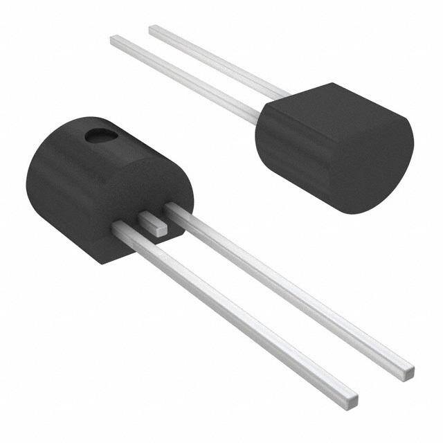
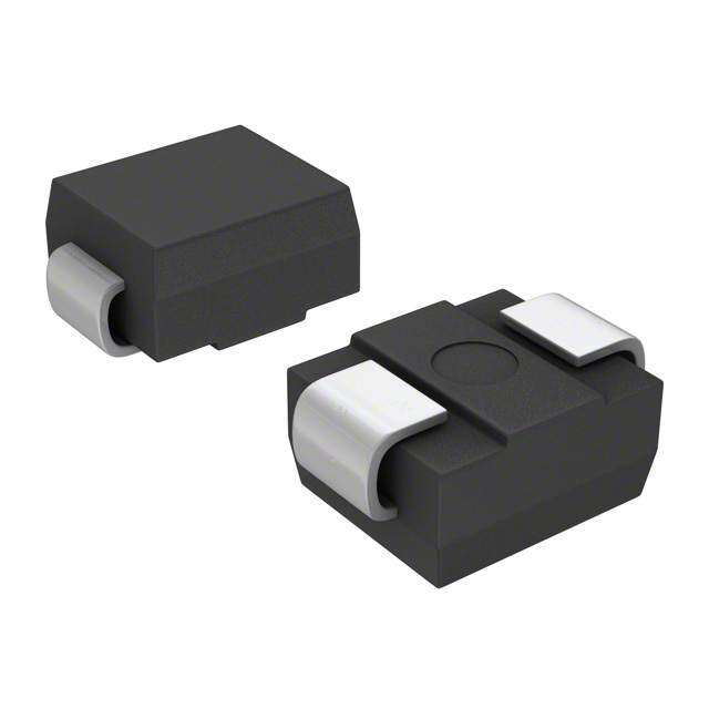
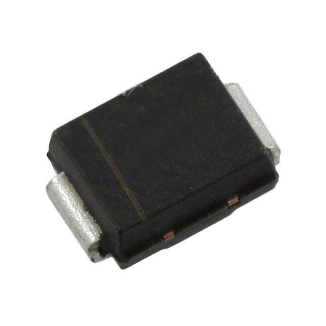
| 描述 | SIDACTOR BI 6V 500A TO92硅对称二端开关元件 6V 500A TO92 SIDACtor Bi |
| 产品分类 | |
| 品牌 | Littelfuse |
| 产品手册 | |
| 产品图片 |
|
| rohs | 符合RoHS无铅 / 符合限制有害物质指令(RoHS)规范要求 |
| 产品系列 | 晶体闸流管,硅对称二端开关元件,Littelfuse P0080ECLSIDACtor® |
| 数据手册 | |
| 产品型号 | P0080ECL |
| 不重复通态电流 | 30 A |
| 产品种类 | 硅对称二端开关元件 |
| 保持电流Ih最大值 | 50 mA |
| 元件数 | 1 |
| 关闭状态漏泄电流(在VDRMIDRM下) | 5 uA |
| 关闭状态电容CO | 35 pF to 260 pF |
| 包装 | 散装 |
| 商标 | Littelfuse |
| 安装风格 | Through Hole |
| 封装 | Bulk |
| 封装/外壳 | TO-226-2,TO-92-2(TO-226AC) |
| 封装/箱体 | TO-92-3 |
| 工作结温 | - 40 C to + 150 C |
| 工厂包装数量 | 2000 |
| 开启状态电压 | 4 V |
| 最大工作温度 | + 85 C |
| 最大转折电流IBO | 800 mA |
| 最小工作温度 | - 40 C |
| 标准包装 | 2,000 |
| 电压-导通 | 25V |
| 电压-断态 | 6V |
| 电压-通态 | 4V |
| 电容 | 260pF |
| 电流-保持(Ih) | 50mA |
| 电流-峰值脉冲(10/1000µs) | 100A |
| 电流-峰值脉冲(8/20µs) | 400A |
| 电流额定值 | 2.2 A |
| 系列 | pxxx0e |
| 转折电流VBO | 25 V |
| 额定重复关闭状态电压VDRM | 6 V |

,TO-226_straightlead.jpg)


- 商务部:美国ITC正式对集成电路等产品启动337调查
- 曝三星4nm工艺存在良率问题 高通将骁龙8 Gen1或转产台积电
- 太阳诱电将投资9.5亿元在常州建新厂生产MLCC 预计2023年完工
- 英特尔发布欧洲新工厂建设计划 深化IDM 2.0 战略
- 台积电先进制程称霸业界 有大客户加持明年业绩稳了
- 达到5530亿美元!SIA预计今年全球半导体销售额将创下新高
- 英特尔拟将自动驾驶子公司Mobileye上市 估值或超500亿美元
- 三星加码芯片和SET,合并消费电子和移动部门,撤换高东真等 CEO
- 三星电子宣布重大人事变动 还合并消费电子和移动部门
- 海关总署:前11个月进口集成电路产品价值2.52万亿元 增长14.8%

PDF Datasheet 数据手册内容提取
SIDACtor® Protection Thyristors Baseband Protection (Voice-DS1) SIDACtor® Series - TO-92 RoHS Pb e3 Description SIDACtor® Series TO-92 are designed to protect baseband equipment such as modems, line cards, CPE and DSL from damaging overvoltage transients. The series provides a robust through-hole solution that enables equipment to comply with global regulatory standards. Features and Benefits • Low voltage overshoot • Fails short circuit when surged in excess of • Low on-state voltage ratings • Does not degrade Agency Approvals • Low capacitance surge capability after multiple surge events • 2nd level interconnect Agency Agency File Number within limit. is Pb-free per IPC/ JEDEC J-STD-609A.01 E133083 Applicable Global Standards Pinout Designation • TIA-968-A • GR 1089 Intra-building • TIA-968-B • IEC 61000-4-5 • ITU K.20/21 Enhanced • YD/T 1082 Pin 1 Pin 3 Level* • YD/T 993 • ITU K.20/21 Basic Level • YD/T 950 Schematic Symbol • GR 1089 Inter-building* * A/B-rated parts require series resistance Electrical Characteristics V V V Capacitance DRM S I I I T Part Number Marking @l =5µA @100V/µs H S T @I=2.2 Amps @1MHz, 2V bias DRM T V min V max mA min mA max A max V max pF min pF max P0080EALxxx P0080EA 6 25 50 800 2.2 4 25 150 P0300EALxxx P0300EA 25 40 50 800 2.2 4 15 140 P0640EALxxx P0640EA 58 77 150 800 2.2 4 40 60 P0720EALxxx P0720EA 65 88 150 800 2.2 4 35 60 P0900EALxxx P0900EA 75 98 150 800 2.2 4 35 55 P1100EALxxx P1100EA 90 130 150 800 2.2 4 30 50 P1300EALxxx P1300EA 120 160 150 800 2.2 4 25 45 P1500EALxxx P1500EA 140 180 150 800 2.2 4 25 40 P1800EALxxx P1800EA 170 220 150 800 2.2 4 25 35 P2300EALxxx P2300EA 190 260 150 800 2.2 4 25 35 P2600EALxxx P2600EA 220 300 150 800 2.2 4 20 35 P3100EALxxx P3100EA 275 350 150 800 2.2 4 20 35 P3500EALxxx P3500EA 320 400 150 800 2.2 4 20 35 Table continues on next page. © 2017 Littelfuse, Inc. Specifications are subject to change without notice. Revised: 02/23/17
SIDACtor® Protection Thyristors Baseband Protection (Voice-DS1) Electrical Characteristics (continued) V V V Capacitance DRM S I I I T @l =5µA @100V/µs H S T @I=2.2 Amps @1MHz, 2V bias Part Number Marking DRM T V Min V Max mA Min mA Max A Max V Max pF Min pF Max P0080EBLxxx P0080EB 6 25 50 800 2.2 4 25 150 P0300EBLxxx P0300EB 25 40 50 800 2.2 4 15 140 P0640EBLxxx P0640EB 58 77 150 800 2.2 4 40 60 P0720EBLxxx P0720EB 65 88 150 800 2.2 4 35 75 P0900EBLxxx P0900EB 75 98 150 800 2.2 4 35 70 P1100EBLxxx P1100EB 90 130 150 800 2.2 4 30 70 P1300EBLxxx P1300EB 120 160 150 800 2.2 4 25 60 P1500EBLxxx P1500EB 140 180 150 800 2.2 4 25 55 P1800EBLxxx P1800EB 170 220 150 800 2.2 4 25 50 xxx P2300EB 190 260 150 800 2.2 4 25 50 P2600EBLxxx P2600EB 220 300 150 800 2.2 4 20 45 P3100EBLxxx P3100EB 275 350 150 800 2.2 4 20 45 P3500EBLxxx P3500EB 320 400 150 800 2.2 4 20 40 P0080ECLxxx P0080EC 6 25 50 800 2.2 4 35 260 P0300ECLxxx P0300EC 25 40 50 800 2.2 4 25 250 P0640ECLxxx P0640EC 58 77 150 800 2.2 4 55 155 P0720ECLxxx P0720EC 65 88 150 800 2.2 4 50 150 P0900ECLxxx P0900EC 75 98 150 800 2.2 4 45 140 P1100ECLxxx P1100EC 90 130 150 800 2.2 4 45 115 P1300ECLxxx P1300EC 120 160 150 800 2.2 4 40 105 P1500ECLxxx P1500EC 140 180 150 800 2.2 4 35 95 P1800ECLxxx P1800EC 170 220 150 800 2.2 4 35 90 P2300ECLxxx P2300EC 190 260 150 800 2.2 4 30 80 P2600ECLxxx P2600EC 220 300 150 800 2.2 4 30 80 P3100ECLxxx P3100EC 275 350 150 800 2.2 4 30 70 P3500ECLxxx P3500EC 320 400 150 800 2.2 4 25 65 Notes: Notes: - Absolute maximum ratings measured at T= 25ºC (unless otherwise noted). - xxx part number suffix: ‘AP’ = Ammo Pack, ‘RP1’ and ‘RP2’ = Reel Pack, - Devices are bi-directional (unless otherwisAe noted). blank = Bulk Pack Surge Ratings I eries 00..52xx730100 12 22xx1100 12 18.2xx2500 1 2 1100xx116600 12 1100xx55PP6600 12 59xx372200 12 1100xx336600 12 1100xx11000000 12 150xx371000 1 2 50/I6TS0M Hz di/dt S A min A min A min A min A min A min A min A min A min A min A/µs max A 20 150 150 90 50 75 75 45 75 20 500 B 25 250 250 150 100 100 125 80 100 25 500 C 50 500 400 200 150 200 175 100 200 30 500 Notes: - Peak pulse current rating (I ) is repetitive and guaranteed for the life of the product that remains in thermal equilibrium. 1 Current waveform in µs - I ratings applicable over tePPmperature range of -40ºC to +85ºC 2 Voltage waveform in µs - TPhPe device must initially be in thermal equilibrium with -40°C < T < +150°C J Thermal Considerations Package Symbol Parameter Value Unit TO-92 T Operating Junction Temperature Range -40 to +150 °C J T Storage Temperature Range -65 to +150 °C S R Thermal Resistance: Junction to Ambient 90 °C/W 0JA © 2017 Littelfuse, Inc. Specifications are subject to change without notice. Revised: 02/23/17
SIDACtor® Protection Thyristors Baseband Protection (Voice-DS1) V-I Characteristics t x t Pulse Waveform r d +I PP tr = rise time to peak value %I Peak td = decay time to half value IT – 100 Value IIHS urrent Waveform = tr x td C IDRM se -V +V ul 50 Half Value P VT VDRM ak e P VS – P P I 0 tr td 0 t – Time (µs) -I Normalized V Change vs. Junction Temperature Normalized DC Holding Current vs. Case Temperature S 2.0 14 1.8 % 12 C) e – 10 25º 1.6 ang 8 IH = C 1.4 Ch S 46 25 °C I(TH 1.2 25°C V of 2 of 1.0 ent 0 tio 0.8 rc -4 Ra e 0.6 P -6 -8 0.4 -40 -20 0 20 40 60 80 100120140 160 -40 -20 0 20 40 60 80 100 120 140 160 Junction Temperature (T ) – °C Case Temperature (T ) - ºC J C Soldering Parameters Pb-Free assembly Reflow Condition (see Fig. 1) Figure 1 t P - Temperature Min (T ) +150°C T s(min) P Critical Zone Pre Heat - Temperature Max (Ts(max)) +200°C Ramp-up TL to TP - Time (Min to Max) (t) 60-180 secs. Atov pereaagke) ramp up rate (Liquiduss Temp (TL) 3°C/sec. Max. eruTS(mTaxL) tL t TS(max) to TL - Ramp-up Rate 3°C/sec. Max. are Ramp-down Reflow - Temperature (TL) (Liquidus) +217°C pmTS(min) Preheat - Temperature (tL) 60-150 secs. eT tS Peak Temp (T) +260(+0/-5)°C P 25 Time within 5°C of actual Peak Temp (tp) 30 secs. Max. time (tto 2 p5eºCak t ote pmepake)rature Time Ramp-down Rate 6°C/sec. Max. Time 25°C to Peak Temp (T) 8 min. Max. P Do not exceed +260°C © 2017 Littelfuse, Inc. Specifications are subject to change without notice. Revised: 02/23/17
SIDACtor® Protection Thyristors Baseband Protection (Voice-DS1) Physical Specifications Environmental Specifications 80% Rated V (V Peak) +125°C or +150°C, Lead Material Copper Alloy High Temp Voltage DRM AC 504 or 1008 hrs. MIL-STD-750 (Method 1040) Blocking JEDEC, JESD22-A-101 Terminal Finish 100% Matte-Tin Plated -65°C to +150°C, 15 min. dwell, 10 up to 100 Temp Cycling cycles. MIL-STD-750 (Method 1051) EIA/JEDEC, UL recognized epoxy meeting flammability JESD22-A104 Body Material classification 94V-0 Biased Temp & 52 V (+85°C) 85%RH, 504 up to 1008 hrs. EIA/ DC Humidity JEDEC, JESD22-A-101 +150°C 1008 hrs. MIL-STD-750 (Method 1031) High Temp Storage JEDEC, JESD22-A-101 Low Temp Storage -65°C, 1008 hrs. 0°C to +100°C, 5 min. dwell, 10 sec. transfer, Thermal Shock 10 cycles. MIL-STD-750 (Method 1056) JEDEC, JESD22-A-106 Autoclave (Pressure +121°C, 100%RH, 2atm, 24 up to 168 hrs. EIA/ Cooker Test) JEDEC, JESD22-A-102 Resistance to Solder +260°C, 30 secs. MIL-STD-750 (Method 2031) Heat Moisture Sensitivity 85%RH, +85°C, 168 hrs., 3 reflow cycles Level (+260°C Peak). JEDEC-J-STD-020, Level 1 Part Numbering Part Marking P xxx0 Ex L xxx XXXXXXX XX Part Marking Code TYPE PACKING OPTIONS (Refer to Electrical Characteristics Table) P = SIDACtor Date Code XXXXX MEDIAN VOLTAGE RoHS COMPLIANT CONSTRUCTION VARIABLE I RATING PP PACKAGE TYPE Packing Options Packing Options Package Type Description Added Suffix Lead Spacing Industry Standard Quantity RP1 0.1 inch (2.54mm) TO-92 Tape and Reel Pack EIA-481-D RP2 0.2 inch (5.08mm) E 2000 TO-92 Ammo Pack AP EIA-468-B TO-92 Bulk Pack N/A N/A Additional Information Datasheet Resources Samples © 2017 Littelfuse, Inc. Specifications are subject to change without notice. Revised: 02/23/17
SIDACtor® Protection Thyristors Baseband Protection (Voice-DS1) Dimensions — TO-92 Ammo Pack Specification — TO-92 MeaTseumrepmereantut rPeoint Inches Millimeters (012.5.70) 0(6.2.355) A A M0.1i7n6 M0.1a9x6 M4.4in7 M4.9a8x (M14.1A6.22X) 0(.62.306) 0.02 (0.5) 0.125 (3.2) MAX(31.22.72) N B 0.500 12.70 (01.87.008) 0.354 D 0.095 0.105 2.41 2.67 (9.0) 0(4.1.05)7 DIA E 0.150 3.81 0.50 0.20 (5.08) (12.7) B G 0.135 0.145 3.43 3.68 Direction of Feed Flat down H 0.088 0.096 2.23 2.44 J 0.176 0.186 4.47 4.73 25 Devices per fold K 0.088 0.096 2.23 2.44 L 0.013 0.019 0.33 0.48 MT1/PIN 1 MT2/PIN 3 M 0.013 0.017 0.33 0.43 1.7 (43) E N 0.60 1.52 Dimensions G M H All leads are insulated from case. Case is electri- a(arned in m inilclihmeesters). cally non-conductive. (Rated at 1600 V for L D one minute from leads to case over th(eAC )o RpMeSrating (167.95) K temperature range.) J Mold flash shall not exceed 0.13 mm per side. The TO-92 is designed to meet 1.7 mechanical standards as set forth (43) in JEDEC publication number 95. 12.9 (327) Tape and Reel Specification — TO-92 FLAT SIDE Inches Millimeters OF TO-92 Dimensions Min Max Min Max A N/A 14.173 N/A 360.0 B 4.016 N/A 102.0 N/A C 3.386 N/A 86.0 N/A A D D 0.795 N/A 20.2 N/A C W1 W1 1.181 1.968 30.0 50.0 B P 0.496 0.504 12.60 12.80 P0 0.498 0.502 12.65 12.75 ROUND SIDE OF TO-92 F(for RP1) 0.090 0.110 2.29 2.80 P F(for RP2) 0.182 0.244 4.63 6.19 H N/A 1.673 N/A 42.50 (RP1) (RP2) H1 W4 H1 N/A 1.270 N/A 32.26 W3 H W 0.674 0.763 17.12 19.38 W2 W W2 0.354 0.370 8.25 9.75 W3 0.236 N/A 6.00 N/A W4 0.020 N/A 0.50 N/A P0 F F Dimension Inches Millimeters Minimum Maximum Minimum Maximum A DNis/Acl aimer N1o4ti.c1e7 -3 I nformatiNon/A f urnished is3 6b0el.i0e ved to be accurate and reliable. However, users should independently evaluate the suitability of and test each product selected for their own applications. Littelfuse products are not designed for, and may not be used in, all applications. B 4R.e0a1d6 c ompleteN D/Ais claimer N1o0t2ic.e0 at www.litNte/Alfu se.com/disclaimer-electronics. C 3.386 N/A 86.0 N/A © 2017 Littelfuse, Inc. D 0Sp.e7c9ifi5c ations are suNbj/eAct to change wi2th0ou.2t n otice. N/A Revised: 02/23/17 W1 1.181 1.968 30.0 50.0 P 0.496 0.504 12.60 12.80 P0 0.498 0.502 12.65 12.75 F (for RP1) 0.090 0.110 2.29 2.80 F (for RP2) 0.182 0.244 4.63 6.19 H N/A 1.673 N/A 42.50 H1 N/A 1.270 N/A 32.26 W 0.674 0.763 17.12 19.38 W2 0.354 0.370 8.25 9.75 W3 0.236 N/A 6.00 N/A W4 0.020 N/A 0.50 N/A Note: Dimensions originally based on inches. Millimeter values may include conversion errors. (cid:14967)