ICGOO在线商城 > OPA2373AIDGST
 Datasheet下载
- 型号: OPA2373AIDGST
- 制造商: Texas Instruments
- 库位|库存: xxxx|xxxx
- 要求:
| 数量阶梯 | 香港交货 | 国内含税 |
| +xxxx | $xxxx | ¥xxxx |
查看当月历史价格
查看今年历史价格
OPA2373AIDGST产品简介:
ICGOO电子元器件商城为您提供OPA2373AIDGST由Texas Instruments设计生产,在icgoo商城现货销售,并且可以通过原厂、代理商等渠道进行代购。 提供OPA2373AIDGST价格参考¥6.04-¥13.66以及Texas InstrumentsOPA2373AIDGST封装/规格参数等产品信息。 你可以下载OPA2373AIDGST参考资料、Datasheet数据手册功能说明书, 资料中有OPA2373AIDGST详细功能的应用电路图电压和使用方法及教程。
| 参数 | 数值 |
| -3db带宽 | - |
| 产品目录 | 集成电路 (IC)半导体 |
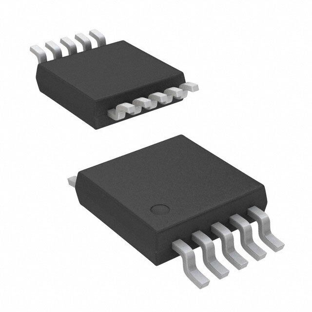
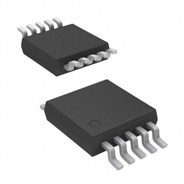
| 描述 | IC OPAMP GP 6.5MHZ RRO 10VSSOP运算放大器 - 运放 Dual 6.5MHz 585uA R-to-R I/O CMOS |
| 产品分类 | Linear - Amplifiers - Instrumentation, OP Amps, Buffer Amps集成电路 - IC |
| 品牌 | Texas Instruments |
| 产品手册 | http://www.ti.com/litv/sbos279e |
| 产品图片 |
|
| rohs | 符合RoHS无铅 / 符合限制有害物质指令(RoHS)规范要求 |
| 产品系列 | 放大器 IC,运算放大器 - 运放,Texas Instruments OPA2373AIDGST- |
| 数据手册 | |
| 产品型号 | OPA2373AIDGST |
| 产品种类 | 运算放大器 - 运放 |
| 供应商器件封装 | 10-VSSOP |
| 共模抑制比—最小值 | 80 dB |
| 关闭 | Shutdown |
| 其它名称 | 296-18503-6 |
| 包装 | Digi-Reel® |
| 压摆率 | 5 V/µs |
| 商标 | Texas Instruments |
| 增益带宽生成 | 6.5 MHz |
| 增益带宽积 | 6.5MHz |
| 安装类型 | 表面贴装 |
| 安装风格 | SMD/SMT |
| 封装 | Reel |
| 封装/外壳 | 10-TFSOP,10-MSOP(0.118",3.00mm 宽) |
| 封装/箱体 | VSSOP-10 |
| 工作温度 | -40°C ~ 125°C |
| 工作电源电压 | 2.7 V to 5.5 V |
| 工厂包装数量 | 250 |
| 技术 | CMOS |
| 放大器类型 | 通用 |
| 最大工作温度 | + 125 C |
| 最小工作温度 | - 40 C |
| 标准包装 | 1 |
| 电压-电源,单/双 (±) | 2.3 V ~ 5.5 V, ±1.15 V ~ 2.75 V |
| 电压-输入失调 | 1mV |
| 电流-电源 | 585µA |
| 电流-输入偏置 | 0.5pA |
| 电流-输出/通道 | - |
| 电源电流 | 1.5 mA |
| 电路数 | 2 |
| 系列 | OPA2373 |
| 设计资源 | http://www.digikey.com/product-highlights/cn/zh/texas-instruments-webench-design-center/3176 |
| 转换速度 | 5 V/us |
| 输入偏压电流—最大 | 10 pA |
| 输入参考电压噪声 | 15 nV |
| 输入补偿电压 | 5 mV |
| 输出类型 | 满摆幅 |
| 通道数量 | 2 Channel |


- 商务部:美国ITC正式对集成电路等产品启动337调查
- 曝三星4nm工艺存在良率问题 高通将骁龙8 Gen1或转产台积电
- 太阳诱电将投资9.5亿元在常州建新厂生产MLCC 预计2023年完工
- 英特尔发布欧洲新工厂建设计划 深化IDM 2.0 战略
- 台积电先进制程称霸业界 有大客户加持明年业绩稳了
- 达到5530亿美元!SIA预计今年全球半导体销售额将创下新高
- 英特尔拟将自动驾驶子公司Mobileye上市 估值或超500亿美元
- 三星加码芯片和SET,合并消费电子和移动部门,撤换高东真等 CEO
- 三星电子宣布重大人事变动 还合并消费电子和移动部门
- 海关总署:前11个月进口集成电路产品价值2.52万亿元 增长14.8%


PDF Datasheet 数据手册内容提取
Product Sample & Technical Tools & Support & Reference Folder Buy Documents Software Community Design OPA373,OPA374 OPA2373,OPA2374,OPA4374 SBOS279F–SEPTEMBER2003–REVISEDSEPTEMBER2016 OPAx373, OPAx374 6.5-MHz, 585-µA, Rail-to-Rail I/O CMOS Operational Amplifier 1 Features 3 Description • LowOffset:5mV(Maximum) The OPA373 and OPA374 families of operational 1 amplifiers are low power and low cost with excellent • LowI :10pA(Maximum) B bandwidth (6.5 MHz) and slew rate (5 V/µs). The • HighBandwidth:6.5MHz input range extends 200 mV beyond the rails and the • Rail-to-RailInputandOutput output range is within 25 mV of the rails. The speed- power ratio and small size make them ideal for • SingleSupply:2.3Vto5.5V portableandbattery-poweredapplications. • Shutdown:OPAx373 The OPA373 family includes a shutdown mode. • Specifiedupto125°C Under logic control, the amplifiers can be switched • MicrosizePackages:5-PinSOT-23, from normal operation to a standby current that is 6-PinSOT-23,8-PinSOT-23,and10-PinVSON lessthan1 µA. The OPA373 and OPA374 families of operational 2 Applications amplifiers are specified for single or dual power • PortableEquipment supplies of 2.7 V to 5.5 V, with operation from 2.3 V • Battery-PoweredDevices to5.5V.Allmodelsarespecifiedfor –40°Cto125°C. • ActiveFilters DeviceInformation(1) • DrivingA/DConverters PARTNUMBER PACKAGE BODYSIZE(NOM) SOIC(8) 4.90mm×3.91mm OPA373 SOT-23(6) 2.90mm×1.60mm SOIC(8) 4.90mm×3.91mm OPA374 SOT-23(5) 2.90mm×1.60mm VSON(10) 3.00mm×3.00mm OPA2373 VSSOP(10) 3.00mm×3.00mm SOIC(8) 4.90mm×3.91mm OPA2374 SOT-23(8) 2.90mm×1.63mm SOIC(14) 8.65mm×3.91mm OPA4374 TSSOP(14) 5.00mm×4.40mm (1) For all available packages, see the orderable addendum at theendofthedatasheet. TypicalApplication VCC VCC R5 + R6 ILOAD R2 R1 + + VBUS – RSHUNT VOUT R3 VCC RL R4 Copyright © 2016, Texas Instruments Incorporated 1 An IMPORTANT NOTICE at the end of this data sheet addresses availability, warranty, changes, use in safety-critical applications, intellectualpropertymattersandotherimportantdisclaimers.PRODUCTIONDATA.
OPA373,OPA374 OPA2373,OPA2374,OPA4374 SBOS279F–SEPTEMBER2003–REVISEDSEPTEMBER2016 www.ti.com Table of Contents 1 Features.................................................................. 1 8.3 FeatureDescription.................................................15 2 Applications........................................................... 1 8.4 DeviceFunctionalModes........................................18 3 Description............................................................. 1 9 ApplicationandImplementation........................ 19 4 RevisionHistory..................................................... 2 9.1 ApplicationInformation............................................19 9.2 TypicalApplication .................................................19 5 DeviceComparisonTable..................................... 3 9.3 SystemExamples ..................................................21 6 PinConfigurationandFunctions......................... 4 10 PowerSupplyRecommendations..................... 23 7 Specifications......................................................... 7 11 Layout................................................................... 23 7.1 AbsoluteMaximumRatings......................................7 11.1 LayoutGuidelines.................................................23 7.2 ESDRatings..............................................................7 11.2 LayoutExample....................................................24 7.3 RecommendedOperatingConditions.......................7 12 DeviceandDocumentationSupport................. 25 7.4 ThermalInformation:OPA373..................................7 7.5 ThermalInformation:OPA374..................................8 12.1 DeviceSupport......................................................25 7.6 ThermalInformation:OPA2373................................8 12.2 DocumentationSupport........................................26 7.7 ThermalInformation:OPA2374................................8 12.3 RelatedLinks........................................................26 7.8 ThermalInformation:OPA4374................................8 12.4 ReceivingNotificationofDocumentationUpdates26 7.9 ElectricalCharacteristics:V =2.7Vto5.5V..........9 12.5 CommunityResources..........................................26 S 7.10 TypicalCharacteristics..........................................11 12.6 Trademarks...........................................................26 12.7 ElectrostaticDischargeCaution............................26 8 DetailedDescription............................................ 15 12.8 Glossary................................................................27 8.1 Overview.................................................................15 13 Mechanical,Packaging,andOrderable 8.2 FunctionalBlockDiagram.......................................15 Information........................................................... 27 4 Revision History ChangesfromRevisionE(May2008)toRevisionF Page • AddedESDRatingtable,FeatureDescriptionsection,DeviceFunctionalModes,ApplicationandImplementation section,PowerSupplyRecommendationssection,Layoutsection,DeviceandDocumentationSupportsection,and Mechanical,Packaging,andOrderableInformationsection ................................................................................................. 1 • DeletedPackage/OrderingInformationtable;refertoPackageOptionAddendumattheendofthisdatasheet................4 • DeletedleadtemperaturespecificationfromAbsoluteMaximumRatings ............................................................................ 7 • ChangedvaluesintheThermalInformationtablestoalignwithJEDECstandards.............................................................. 7 2 SubmitDocumentationFeedback Copyright©2003–2016,TexasInstrumentsIncorporated ProductFolderLinks:OPA373 OPA374OPA2373 OPA2374 OPA4374
OPA373,OPA374 OPA2373,OPA2374,OPA4374 www.ti.com SBOS279F–SEPTEMBER2003–REVISEDSEPTEMBER2016 5 Device Comparison Table NO.OF PACKAGE-PIN DEVICE SHUTDOWN CHANNELS SOIC SOT-23 VSON VSSOP TSSOP OPA373 1 Yes 8 6 — — — OPA2373 2 Yes — — 10 10 — OPA374 1 No 8 5 — — — OPA2374 2 No 8 8 — — — OPA4374 4 No 14 — — — 14 Copyright©2003–2016,TexasInstrumentsIncorporated SubmitDocumentationFeedback 3 ProductFolderLinks:OPA373 OPA374OPA2373 OPA2374 OPA4374
OPA373,OPA374 OPA2373,OPA2374,OPA4374 SBOS279F–SEPTEMBER2003–REVISEDSEPTEMBER2016 www.ti.com 6 Pin Configuration and Functions OPA373:DBVPackage OPA373:DPackage 6-PinSOT-23 8-PinSOIC TopView TopView Out(1) 1 A7 6 V+ NC(2) 1 8 Enable 5 V- 2 5 Enable -IN 2 7 V+ +IN 3 4 -IN +IN 3 6 OUT V- 4 5 NC(2) (1)Pin1ofthe6-pinSOT-23isdetermined byorientingthepackagemarkingas (2)NCindicatesnointernalconnection. shown. PinFunctions:OPA373 PIN I/O DESCRIPTION NAME SOIC SOT-23 Enable 8 5 I Enable –IN 2 4 I Negative(inverting)input +IN 3 3 I Positive(noninverting)input NC 1,5 — — Nointernalconnection(canbeleftfloating) OUT 6 1 O Output V– 4 2 — Negative(lowest)powersupply V+ 7 6 — Positive(highest)powersupply OPA2373:DGSPackage OPA2373:DRCPackage 10-PinVSON 10-PinVSSOP TopView TopView OUTA 1 10 V+ OUTA V+ Exposed -INA 2 9 OUTB -INA thermal OUTB A die pad on +INA 3 8 -IN B +INA underside -IN B B (Must be V- 4 7 +IN B V- connected to V-) +INB EnableA 5 6 Enable B EnableA EnableB PinFunctions:OPA2373 PIN I/O DESCRIPTION NAME VSON VSSOP EnableA 5 5 I EnableAamplifier EnableB 6 6 I EnableBamplifier –INA 2 2 I Invertinginput,channelA +INA 3 3 I Noninvertinginput,channelA –INB 8 8 I Invertinginput,channelB +INB 7 7 I Noninvertinginput,channelB OUTA 1 1 O Output,channelA OUTB 9 9 O Output,channelB V– 4 4 — Negative(lowest)powersupply V+ 10 10 — Positive(highest)powersupply 4 SubmitDocumentationFeedback Copyright©2003–2016,TexasInstrumentsIncorporated ProductFolderLinks:OPA373 OPA374OPA2373 OPA2374 OPA4374
OPA373,OPA374 OPA2373,OPA2374,OPA4374 www.ti.com SBOS279F–SEPTEMBER2003–REVISEDSEPTEMBER2016 OPA374:DBVPackage OPA374:DPackage 5-PinSOT-23 8-PinSOIC TopView TopView Out 1 5 V+ NC(1) 1 8 NC(1) V- 2 -IN 2 7 V+ +IN 3 4 -IN +IN 3 6 OUT V- 4 5 NC(1) (1)NCindicatesnointernalconnection. PinFunctions:OPA374 PIN I/O DESCRIPTION NAME SOIC SOT-23 –IN 2 4 I Negative(inverting)input +IN 3 3 I Positive(noninverting)input NC 1,5,8 — — Nointernalconnection(canbeleftfloating) OUT 6 1 O Output V– 4 2 — Negative(lowest)powersupply V+ 7 5 — Positive(highest)powersupply OPA2374:DCNPackage OPA2374:DPackage 8-PinSOT-23 8-PinSOIC TopView TopView OUTA 1 8 V+ OUTA 1 8 V+ A A -INA 2 7 OUTB -INA 2 7 OUTB B B +INA 3 6 -IN B +INA 3 6 -IN B V- 4 5 +IN B V- 4 5 +IN B PinFunctions:OPA2374 PIN I/O DESCRIPTION NAME SOIC SOT-23 –INA 2 2 I Invertinginput,channelA +INA 3 3 I Noninvertinginput,channelA –INB 6 6 I Invertinginput,channelB +INB 5 5 I Noninvertinginput,channelB OUTA 1 1 O Output,channelA OUTB 7 7 O Output,channelB V– 4 4 — Negative(lowest)powersupply V+ 8 8 — Positive(highest)powersupply Copyright©2003–2016,TexasInstrumentsIncorporated SubmitDocumentationFeedback 5 ProductFolderLinks:OPA373 OPA374OPA2373 OPA2374 OPA4374
OPA373,OPA374 OPA2373,OPA2374,OPA4374 SBOS279F–SEPTEMBER2003–REVISEDSEPTEMBER2016 www.ti.com OPA4374:PWPackage OPA4374:DPackage 14-PinTSSOP 14-PinSOIC TopView TopView OUTA 1 14 OUTD OUTA 1 14 OUTD -INA 2 13 -IN D -INA 2 13 -IN D A D A D +INA 3 12 +IN D +INA 3 12 +IN D V+ 4 11 V- V+ 4 11 V- +IN B 5 10 +IN C +IN B 5 10 +IN C B C B C -IN B 6 9 -IN C -IN B 6 9 -IN C OUTB 7 8 OUTC OUTB 7 8 OUTC PinFunctions:OPA4374 PIN I/O DESCRIPTION NAME SOIC TSSOP –INA 2 2 I Invertinginput,channelA +INA 3 3 I Noninvertinginput,channelA –INB 6 6 I Invertinginput,channelB +INB 5 5 I Noninvertinginput,channelB –INC 9 9 I Invertinginput,channelC +INC 10 10 I Noninvertinginput,channelC –IND 13 13 I Invertinginput,channelD +IND 12 12 I Noninvertinginput,channelD OUTA 1 1 O Output,channelA OUTB 7 7 O Output,channelB OUTC 8 8 O Output,channelC OUTD 14 14 O Output,channelD V– 11 11 — Negative(lowest)powersupply V+ 4 4 — Positive(highest)powersupply 6 SubmitDocumentationFeedback Copyright©2003–2016,TexasInstrumentsIncorporated ProductFolderLinks:OPA373 OPA374OPA2373 OPA2374 OPA4374
OPA373,OPA374 OPA2373,OPA2374,OPA4374 www.ti.com SBOS279F–SEPTEMBER2003–REVISEDSEPTEMBER2016 7 Specifications 7.1 Absolute Maximum Ratings overoperatingfree-airtemperaturerange(unlessotherwisenoted)(1) MIN MAX UNIT Supply 7 Voltage V Signalinputpin(2) −0.5 (V+)+0.5 Signalinputpin(2) –10 10 mA Current Outputshort-circuit(3) Continuous Operating,T –55 150 A Temperature Junction,T 150 °C J Storage,T –65 150 stg (1) StressesbeyondthoselistedunderAbsoluteMaximumRatingsmaycausepermanentdamagetothedevice.Thesearestressratings only,whichdonotimplyfunctionaloperationofthedeviceattheseoranyotherconditionsbeyondthoseindicatedunderRecommended OperatingConditions.Exposuretoabsolute-maximum-ratedconditionsforextendedperiodsmayaffectdevicereliability. (2) Inputterminalsarediode-clampedtothepower-supplyrails.Inputsignalsthatcanswingmorethan0.5Vbeyondthesupplyrailsmust becurrentlimitedto10mAorless. (3) Short-circuittoground,oneamplifierperpackage. 7.2 ESD Ratings VALUE UNIT Human-bodymodel(HBM),perANSI/ESDA/JEDECJS-001(1) ±3000 V Electrostaticdischarge V (ESD) Charged-devicemodel(CDM),perJEDECspecificationJESD22-C101(2) ±1000 (1) JEDECdocumentJEP155statesthat500-VHBMallowssafemanufacturingwithastandardESDcontrolprocess. (2) JEDECdocumentJEP157statesthat250-VCDMallowssafemanufacturingwithastandardESDcontrolprocess. 7.3 Recommended Operating Conditions overoperatingfree-airtemperaturerange(unlessotherwisenoted) MIN MAX UNIT Supplyvoltage ±1.35(2.7) ±2.75(5.5) V T Operatingtemperature –40 125 °C A 7.4 Thermal Information: OPA373 OPA373 THERMALMETRIC(1) D(SOIC) DBV(SOT-23) UNIT 8PINS 6PINS R Junction-to-ambientthermalresistance 128.4 184.3 °C/W θJA R Junction-to-case(top)thermalresistance 76.7 146.2 °C/W θJC(top) R Junction-to-boardthermalresistance 68.8 36.4 °C/W θJB ψ Junction-to-topcharacterizationparameter 27.9 33.6 °C/W JT ψ Junction-to-boardcharacterizationparameter 68.3 35.9 °C/W JB R Junction-to-case(bottom)thermalresistance — — °C/W θJC(bot) (1) Formoreinformationabouttraditionalandnewthermalmetrics,seetheSemiconductorandICPackageThermalMetricsapplication report. Copyright©2003–2016,TexasInstrumentsIncorporated SubmitDocumentationFeedback 7 ProductFolderLinks:OPA373 OPA374OPA2373 OPA2374 OPA4374
OPA373,OPA374 OPA2373,OPA2374,OPA4374 SBOS279F–SEPTEMBER2003–REVISEDSEPTEMBER2016 www.ti.com 7.5 Thermal Information: OPA374 OPA374 THERMALMETRIC(1) D(SOIC) DBV(SOT-23) UNIT 8PINS 5PINS R Junction-to-ambientthermalresistance 125.1 220.1 °C/W θJA R Junction-to-case(top)thermalresistance 71.7 129 °C/W θJC(top) R Junction-to-boardthermalresistance 65.5 46.4 °C/W θJB ψ Junction-to-topcharacterizationparameter 26.2 21 °C/W JT ψ Junction-to-boardcharacterizationparameter 65 45.4 °C/W JB R Junction-to-case(bottom)thermalresistance — — °C/W θJC(bot) (1) Formoreinformationabouttraditionalandnewthermalmetrics,seetheSemiconductorandICPackageThermalMetricsapplication report. 7.6 Thermal Information: OPA2373 OPA2373 THERMALMETRIC(1) DGS(VSON) DRC(VSSOP) UNIT 10PINS 10PINS R Junction-to-ambientthermalresistance 170.6 56.4 °C/W θJA R Junction-to-case(top)thermalresistance 59.8 76.7 °C/W θJC(top) R Junction-to-boardthermalresistance 91 30.6 °C/W θJB ψ Junction-to-topcharacterizationparameter 10.4 3.7 °C/W JT ψ Junction-to-boardcharacterizationparameter 89.6 30.7 °C/W JB R Junction-to-case(bottom)thermalresistance — 11.4 °C/W θJC(bot) (1) Formoreinformationabouttraditionalandnewthermalmetrics,seetheSemiconductorandICPackageThermalMetricsapplication report. 7.7 Thermal Information: OPA2374 OPA2374 THERMALMETRIC(1) D(SOIC) DCN(SOT-23) UNIT 8PINS 8PINS R Junction-to-ambientthermalresistance 117.8 171.3 °C/W θJA R Junction-to-case(top)thermalresistance 63.1 73.5 °C/W θJC(top) R Junction-to-boardthermalresistance 58.4 106.3 °C/W θJB ψ Junction-to-topcharacterizationparameter 19.3 15.4 °C/W JT ψ Junction-to-boardcharacterizationparameter 57.9 105.5 °C/W JB R Junction-to-case(bottom)thermalresistance — — °C/W θJC(bot) (1) Formoreinformationabouttraditionalandnewthermalmetrics,seetheSemiconductorandICPackageThermalMetricsapplication report. 7.8 Thermal Information: OPA4374 OPA4374 THERMALMETRIC(1) D(SOIC) PW(TSSOP) UNIT 14PINS 14PINS R Junction-to-ambientthermalresistance 86.5 112.7 °C/W θJA R Junction-to-case(top)thermalresistance 45 34.1 °C/W θJC(top) R Junction-to-boardthermalresistance 41.1 57.1 °C/W θJB ψ Junction-to-topcharacterizationparameter 12.3 2.9 °C/W JT ψ Junction-to-boardcharacterizationparameter 40.8 56.1 °C/W JB R Junction-to-case(bottom)thermalresistance — — °C/W θJC(bot) (1) Formoreinformationabouttraditionalandnewthermalmetrics,seetheSemiconductorandICPackageThermalMetricsapplication report. 8 SubmitDocumentationFeedback Copyright©2003–2016,TexasInstrumentsIncorporated ProductFolderLinks:OPA373 OPA374OPA2373 OPA2374 OPA4374
OPA373,OPA374 OPA2373,OPA2374,OPA4374 www.ti.com SBOS279F–SEPTEMBER2003–REVISEDSEPTEMBER2016 7.9 Electrical Characteristics: V = 2.7 V to 5.5 V S AtT =25°C,R =10kΩconnectedtoV /2,andV =V /2(unlessotherwisenoted) A L S OUT S PARAMETER TESTCONDITIONS MIN TYP MAX UNIT OFFSETVOLTAGE VOS Inputoffsetvoltage VS=5V 1 5 mV Inputoffsetvoltage versustemperature TA=–40°Cto125°C 6.5 mV Inputoffsetvoltage dVOS/dT versusdrift TA=–40°Cto+125°C 3 µV/°C PSRR Inputoffsetvoltage VS=2.7Vto5.5V, TA=25°C 25 100 µV/V versuspowersupply VCM<(V+)–2V TA=–40°Cto125°C 150 0.4 µV/V Channelseparation,DC Atf=1kHz 128 dB INPUTVOLTAGE Common-modevoltage VCM range (V–)–0.2 (V+)+0.2 V TA=25°C 80 90 (V–)–0.2V<VCM<(V+)–2V dB Common-moderejection TA=–40°Cto125°C 70 CMRR ratio VS=5.5V, TA=25°C 66 dB (V–)–0.2V<VCM<(V+)+0.2V TA=–40°Cto125°C 60 dB INPUTBIASCURRENT IB Inputbiascurrent ±0.5 ±10 pA IOS Inputoffsetcurrent ±0.5 ±10 pA INPUTIMPEDANCE Differential 1013||3 Ω||pF Common-mode 1013||6 Ω||pF NOISE Inputvoltagenoise VCM<(V+)–2V,f=0.1Hzto10Hz 10 µVPP en Inputvoltagenoisedensity VCM<(V+)–2V,f=10kHz 15 nV/√Hz in Inputcurrentnoisedensity VCM<(V+)–2V,f=10kHz 4 fA/√Hz OPEN-LOOPGAIN VS=5V,RL=100kΩ, TA=25°C 94 110 dB 0.025V<VO<4.975V TA=–40°Cto125°C 80 AOL Open-loopvoltagegain VS=5V,RL=5kΩ, TA=25°C 94 106 dB 0.125V<VO<4.875V TA=–40°Cto125°C 80 OUTPUT TA=25°C 18 25 mV RL=100kΩ Voltageoutputswingfrom TA=–40°Cto125°C 25 mV rail TA=25°C 100 125 mV RL=5kΩ TA=–40°Cto125°C 125 mV ISC Short-circuitcurrent SeeTypicalCharacteristics CLOAD Capacitiveloaddrive SeeTypicalCharacteristics Open-loopoutput RO impedance f=1MHz,IO=0mA 220 Ω Copyright©2003–2016,TexasInstrumentsIncorporated SubmitDocumentationFeedback 9 ProductFolderLinks:OPA373 OPA374OPA2373 OPA2374 OPA4374
OPA373,OPA374 OPA2373,OPA2374,OPA4374 SBOS279F–SEPTEMBER2003–REVISEDSEPTEMBER2016 www.ti.com Electrical Characteristics: V = 2.7 V to 5.5 V (continued) S AtT =25°C,R =10kΩconnectedtoV /2,andV =V /2(unlessotherwisenoted) A L S OUT S PARAMETER TESTCONDITIONS MIN TYP MAX UNIT FREQUENCYRESPONSE GBW Gain-bandwidthproduct CL=100pF 6.5 MHz SR Slewrate CL=100pF,G=+1 5 V/µs 0.1%,CL=100pF,VS=5V, 1 µs 2-Vstep,G=+1 tS Settlingtime 0.01%,CL=100pF,VS=5V, 1.5 µs 2-Vstep,G=+1 Overloadrecoverytime CL=100pF,VIN●Gain>VS 0.3 µs THD+N Totalharmonicdistortion+ CL=100pF,VS=5V,VO=3VPP, 0.0013% noise G=+1,f=1kHz ENABLEORSHUTDOWN tOFF Turnofftime 3 µs tON Turnontime 12 µs VL Logiclowthreshold Shutdown V– (V–)+0.8 V VH Logichighthreshold Amplifierisactive (V–)+2 V+ V InputbiascurrentofEnable 0.2 µA pin Quiescentcurrentat IQ(sd) shutdown(peramplifier) <0.5 1 µA POWERSUPPLY VS Specifiedvoltagerange 2.7 5.5 V Operatingvoltagerange 2.3to5.5 V Quiescentcurrent TA=25°C 585 750 µA IQ (peramplifier) IO=0mA TA=–40°Cto125°C 800 µA TEMPERATURE Specifiedrange –40 125 °C TA Operatingrange –55 150 °C Tstg Storagerange –65 150 °C 10 SubmitDocumentationFeedback Copyright©2003–2016,TexasInstrumentsIncorporated ProductFolderLinks:OPA373 OPA374OPA2373 OPA2374 OPA4374
OPA373,OPA374 OPA2373,OPA2374,OPA4374 www.ti.com SBOS279F–SEPTEMBER2003–REVISEDSEPTEMBER2016 7.10 Typical Characteristics AtT =25°C,R =10kΩconnectedtoV /2,andV =V /2(unlessotherwisenoted) A L S OUT S 120 30 120 100 0 100 Gain Open-Loop Gain (dB) 86420000 Phase ----369100020 Phase Margin ()° PSRR and CMRR (dB) 864000 PSRR CMRR 0 -150 20 -20 -180 0 10 100 1k 10k 100k 1M 10M 100 1k 10k 100k 1M 10M Frequency (Hz) Frequency (Hz) Figure1.Open-LoopGainandPhasevsFrequency Figure2.Power-SupplyandCommon-Mode RejectionRatiovsFrequency 1000 0.100 R = 5kW %) L e ( s ÖHz) +Noi G = 10V/V oise (nV/ 100 Distortion 0.010 Voltage N Harmonic al Tot G = 1V/V 10 0.001 10 100 1k 10k 100k 10 100 1k 10k 100k Frequency (Hz) Frequency (Hz) Figure3.InputVoltageNoiseSpectralDensityvsFrequency Figure4.TotalHarmonicDistortion+NoisevsFrequency 130 120 V = 5.5V R = 100kW S L 110 120 VCM=-0.2V to 3.5V 100 B) , PSRR (dOL 110100 RL= 5kW CMRR (dB) 987000 VCM=-0.2V to 5.7V A PSRR 60 90 50 80 40 -50 -25 0 25 50 75 100 125 150 -50 -25 0 25 50 75 100 125 150 Temperature (°C) Temperature (°C) Figure5.Open-LoopGainandPower-Supply Figure6.Common-ModeRejectionRatiovsTemperature RejectionRatiovsTemperature Copyright©2003–2016,TexasInstrumentsIncorporated SubmitDocumentationFeedback 11 ProductFolderLinks:OPA373 OPA374OPA2373 OPA2374 OPA4374
OPA373,OPA374 OPA2373,OPA2374,OPA4374 SBOS279F–SEPTEMBER2003–REVISEDSEPTEMBER2016 www.ti.com Typical Characteristics (continued) AtT =25°C,R =10kΩconnectedtoV /2,andV =V /2(unlessotherwisenoted) A L S OUT S 800 800 V = 1/2[(V+)-(V-)] OUT 700 700 A) A) m m nt ( nt ( e 600 e 600 urr urr C C ent 500 ent 500 c c s s e e ui ui Q Q 400 400 300 300 -50 -25 0 25 50 75 100 125 150 2.0 2.5 3.0 3.5 4.0 4.5 5.0 5.5 Temperature (°C) Supply Voltage (V) Figure7.QuiescentCurrentvsTemperature Figure8.QuiescentCurrentvsSupplyVoltage 16 12 +I 14 SC A) +ISC A) 10 m 12 m urrent ( 10 urrent ( 8 -ISC uit C 8 -ISC uit C 6 c c Cir 6 Cir 4 ort- 4 ort- h h S S 2 2 0 0 -50 -25 0 25 50 75 100 125 2.0 2.5 3.0 3.5 4.0 4.5 5.0 5.5 Temperature (°C) Power-Supply Voltage (V) Figure9.Short-CircuitCurrentvsTemperature Figure10.ContinuousShort-CircuitCurrent vsPower-SupplyVoltage 10k 3 2 1k A) Current (p 100 oltage (V) 01 put Bias 10 Output V -1 n I 1 -2 -2555°C°C 150°C 0.1 -3 -50 -25 0 25 50 75 100 125 0 2 4 6 8 10 12 14 16 18 20 Temperature (°C) Output Current (mA) Figure11.InputBiasCurrentvsTemperature Figure12.OutputVoltageSwingvsOutputCurrent 12 SubmitDocumentationFeedback Copyright©2003–2016,TexasInstrumentsIncorporated ProductFolderLinks:OPA373 OPA374OPA2373 OPA2374 OPA4374
OPA373,OPA374 OPA2373,OPA2374,OPA4374 www.ti.com SBOS279F–SEPTEMBER2003–REVISEDSEPTEMBER2016 Typical Characteristics (continued) AtT =25°C,R =10kΩconnectedtoV /2,andV =V /2(unlessotherwisenoted) A L S OUT S 6 V = 5.5V S 5 V = 5V )P S VP 4 e ( on ag ati ut Volt 3 VS= 2.5V Popul utp 2 O 1 0 10k 100k 1M 10M -5 -4 -3 -2 -1 0 1 2 3 4 5 5.5 Frequency (Hz) Offset Voltage (mV) Figure13.MaximumOutputVoltagevsFrequency Figure14.OffsetVoltageProductionDistribution Typical production distribution C = 100pF L of packaged units. n o v ati di ul V/ op m P 0 5 1 2 3 4 5 6 7 8 9 10 11 12 13 14 15 16 Offset Voltage Drift (mV/°C) 200ns/div Figure15.OffsetVoltageDriftMagnitude Figure16.Small-SignalStepResponse ProductionDistribution 60 Refer to theCapacitive Load C = 100pF L and Stabilitysection for tips %) 50 on improving performance. ot ( o 40 h s er G = +1V/V v v O 30 di al V/ n 1 g Si 20 all- G = 10V/V Sm 10 RFB= 10kW 0 10 100 1k 10k Load Capacitance (pF) 400ns/div Figure17.Small-SignalOvershootvsLoadCapacitance Figure18.Large-SignalStepResponse Copyright©2003–2016,TexasInstrumentsIncorporated SubmitDocumentationFeedback 13 ProductFolderLinks:OPA373 OPA374OPA2373 OPA2374 OPA4374
OPA373,OPA374 OPA2373,OPA2374,OPA4374 SBOS279F–SEPTEMBER2003–REVISEDSEPTEMBER2016 www.ti.com Typical Characteristics (continued) AtT =25°C,R =10kΩconnectedtoV /2,andV =V /2(unlessotherwisenoted) A L S OUT S 100 140 G = +1V/V,All Channels R = 5kW 120 L B) e (s)m 10 ation(d 18000 Tim 0.01% par ng Se 60 Settli 1 0.1% annel 40 h C 20 0.1 0 1 10 100 10 100 1K 10K 100K 1M 10M 100M Closed-Loop Gain (V/V) Frequency(Hz) Figure19.SettlingTimevsClosed-LoopGain Figure20.ChannelSeparationvsFrequency 14 SubmitDocumentationFeedback Copyright©2003–2016,TexasInstrumentsIncorporated ProductFolderLinks:OPA373 OPA374OPA2373 OPA2374 OPA4374
OPA373,OPA374 OPA2373,OPA2374,OPA4374 www.ti.com SBOS279F–SEPTEMBER2003–REVISEDSEPTEMBER2016 8 Detailed Description 8.1 Overview The OPAx373 and OPAx374 operational amplifiers (op amps) are suitable for a broad range of general-purpose applications. As unity-gain stable devices and outstanding AC performance, these op amps are ideal for audio applications. The class AB output stage is capable of driving 100-kΩ loads connected to any point between V+ and ground. These devices are well-suited for nearly any single-supply application up to a supply voltage of 5.5 V because the input common-mode voltage range includes both rails. Rail-to-rail input and output swing significantlyincreasestheoveralldevicedynamicrange,especiallyinlow-supplyapplications. 8.2 Functional Block Diagram V+ Reference Current V V IN+ IN- VBIAS1 Class AB Control VO Circuitry V BIAS2 V- (Ground) Copyright © 2016,Texas Instruments Incorporated 8.3 Feature Description 8.3.1 OperatingVoltage The OPA373 and OPA374 op amps are specified and tested over a power-supply range of 2.7 V to 5.5 V (±1.35 V to ±2.75 V). However, the supply voltage may range from 2.3 V to 5.5 V (±1.15 V to ±2.75 V). Supply voltages higher than 7 V (absolute maximum) can permanently damage the amplifier. Parameters that vary over supplyvoltageortemperatureareshownintheTypicalCharacteristics. Copyright©2003–2016,TexasInstrumentsIncorporated SubmitDocumentationFeedback 15 ProductFolderLinks:OPA373 OPA374OPA2373 OPA2374 OPA4374
OPA373,OPA374 OPA2373,OPA2374,OPA4374 SBOS279F–SEPTEMBER2003–REVISEDSEPTEMBER2016 www.ti.com Feature Description (continued) 8.3.2 Common-ModeVoltageRange The input common-mode voltage range of the OPA373 and OPA374 series extends 200 mV beyond the supply rails. This extended range is achieved with a complementary input stage: an N-channel input differential pair in parallel with a P-channel differential pair. The N-channel pair is active for input voltages close to the positive rail, typically (V+) − 1.65 V to 200 mV above the positive supply, while the P-channel pair is on for inputs from 200 mV below the negative supply to approximately (V+) − 1.65 V. There is a 500-mV transition region, typically (V+) − 1.9 V to (V+) − 1.4 V, in which both pairs are on. This 500-mV transition region, shown in Figure 21, can vary ±300 mV with process variation. Thus, the transition region (that is, both stages on) can range from (V+) − 2.2 V to (V+) − 1.7 V on the low end, up to (V+) − 1.6 V to (V+) − 1.1 V on the high end. Within the 500-mV transition region, PSRR, CMRR, offset voltage, offset drift, and THD may be degraded, compared to deviceoperationoutsidethisregion. 2.0 1.5 1.0 V) m e ( 0.5 g olta 0 V et -0.5 s Off -1.0 -1.5 V- V+ -2.0 -0.5 0 0.5 1.0 1.5 2.0 2.5 3.0 3.5 4.0 4.5 5.0 5.5 6.0 Common-ModeVoltage(V) Figure21. BehaviorofTypicalTransitionRegionatRoomTemperature 8.3.3 Rail-to-RailInput The input common-mode range extends from (V−) − 0.2 V to (V+) + 0.2 V. For normal operation, inputs must be limited to this range. The absolute maximum input voltage is 500 mV beyond the supplies. Inputs greater than the input common-mode range but less than the maximum input voltage, while not valid, do not cause any damage to the op amp. Unlike some other op amps, if input current is limited, the inputs may go beyond the supplieswithoutphaseinversion,asshowninFigure22. G = +1V/V, V = 5V S V IN 5V V OUT v di V/ 1 0V 1ms/div Figure22. OPA373:NoPhaseInversionWithInputsGreaterThanthePower-SupplyVoltage Normally, input bias current is approximately 500 fA; however, input voltages exceeding the power supplies by more than 500 mV can cause excessive current to flow in or out of the input pins. Momentary voltages greater than 500 mV beyond the power supply can be tolerated if the current on the input pins is limited to 10 mA. This limiting is easily accomplished with an input resistor; see Figure 23. Many input signals are inherently current- limitedtolessthan10mA,therefore,alimitingresistorisnotrequired. 16 SubmitDocumentationFeedback Copyright©2003–2016,TexasInstrumentsIncorporated ProductFolderLinks:OPA373 OPA374OPA2373 OPA2374 OPA4374
OPA373,OPA374 OPA2373,OPA2374,OPA4374 www.ti.com SBOS279F–SEPTEMBER2003–REVISEDSEPTEMBER2016 Feature Description (continued) V+ I OVERLOAD 10mAmax R OPA373 VOUT V IN Copyright © 2016,Texas Instruments Incorporated Figure23. InputCurrentProtectionforVoltagesExceedingtheSupplyVoltage 8.3.4 Rail-to-RailOutput A class AB output stage with common-source transistors is used to achieve rail-to-rail output. For light resistive loads ( > 100 kΩ), the output voltage can typically swing to within 18 mV from the supply rails. With moderate resistiveloads(5kΩto50kΩ),theoutputcantypicallyswingtowithin100mVfromthesupplyrailsandmaintain highopen-loopgain.SeeFigure12formoreinformation. 8.3.5 CapacitiveLoadandStability The OPA373 series op amps can drive a wide range of capacitive loads. However, under certain conditions, all op amps may become unstable. Op amp configuration, gain, and load value are some of the factors to consider when determining stability. An op amp in unity-gain configuration is the most susceptible to the effects of capacitive load. The capacitive load reacts with the op amp output resistance, along with any additional load resistance, to create a pole in the small-signal response that degrades the phase margin. The OPA373 series op amps perform well in unity-gain configuration, with a pure capacitive load up to approximately 250 pF. Increased gainsallowtheamplifiertodrivemorecapacitance.SeeFigure17forfurtherdetails. One method of improving capacitive load drive in the unity-gain configuration is to insert a small (10-Ω to 20-Ω) resistor,R ,inserieswiththeoutput,asshowninFigure24.Thisconfigurationsignificantlyreducesringingwhile S maintaining DC performance for purely capacitive loads. When there is a resistive load in parallel with the capacitive load, R must be placed within the feedback loop as shown to allow the feedback loop to compensate S forthevoltagedividercreatedbyR andR . S L V+ R S 10Wto 20W OPA373 V OUT V IN R C L L Copyright © 2016,Texas Instruments Incorporated Figure24. SeriesResistorinUnity-GainConfigurationImprovesCapacitiveLoadDrive Copyright©2003–2016,TexasInstrumentsIncorporated SubmitDocumentationFeedback 17 ProductFolderLinks:OPA373 OPA374OPA2373 OPA2374 OPA4374
OPA373,OPA374 OPA2373,OPA2374,OPA4374 SBOS279F–SEPTEMBER2003–REVISEDSEPTEMBER2016 www.ti.com Feature Description (continued) In unity-gain inverter configuration, phase margin can be reduced by the reaction between the capacitance at the op amp input and the gain setting resistors, thus degrading capacitive load drive. Best performance is achieved by using small-valued resistors. However, when large-valued resistors cannot be avoided, a small (4-pF to 6-pF) capacitor, C , can be inserted in the feedback, as shown in Figure 25. This technique significantly reduces FB overshoot by compensating the effect of capacitance, C , which includes the amplifier input capacitance and IN printed-circuitboard(PCB)parasiticcapacitance. C FB R F V+ R I V IN OPA373 V OUT C IN C L Copyright © 2016,Texas Instruments Incorporated Figure25. ImprovingCapacitiveLoadDrive For example, when driving a 100-pF load in unity-gain inverter configuration, adding a 6-pF capacitor in parallel withthe10-kΩfeedbackresistordecreasesovershootfrom57%to12%,asshowninFigure26. 60 G =-1V/V 50 RFB= 10kW %) 40 ot ( ho 30 s er v O 20 10 C = 6pF FB 0 10 100 1k 10k Load Capacitance (pF) Figure26. ImprovingCapacitiveLoadDrive 8.3.6 EnableorShutdown The OPA373 and OPA374 series op amps typically require 585-µA quiescent current. The enable or shutdown featureoftheOPA373allowstheopamptobeshutofftoreducethiscurrenttolessthan1 µA. 8.4 Device Functional Modes The OPAx374 has a single functional mode and is operational when the power-supply voltage is greater than 2.7V(±1.35V).ThemaximumpowersupplyvoltagefortheOPAx374is5.5V(±2.75V). The OPAx373 has two functional modes: active and shutdown. When the voltage at the Enable pin is from V– to (V–)+0.8V,thedeviceisinshutdownandconsumeslessthan0.5 µAofquiescentcurrent(typical).Toactivate, or enable, the device, the voltage at the Enable pin must be from (V–) + 2 V to V+. When active, the power- supplyrequirementsarethesameastheOPAx374. 18 SubmitDocumentationFeedback Copyright©2003–2016,TexasInstrumentsIncorporated ProductFolderLinks:OPA373 OPA374OPA2373 OPA2374 OPA4374
OPA373,OPA374 OPA2373,OPA2374,OPA4374 www.ti.com SBOS279F–SEPTEMBER2003–REVISEDSEPTEMBER2016 9 Application and Implementation NOTE Information in the following applications sections is not part of the TI component specification, and TI does not warrant its accuracy or completeness. TI’s customers are responsible for determining suitability of components for their purposes. Customers should validateandtesttheirdesignimplementationtoconfirmsystemfunctionality. 9.1 Application Information TheOPA373andOPA374seriesopampsareunity-gainstableandsuitableforawiderangeofgeneral-purpose applications. Rail-to-rail input and output make them ideal for driving sampling analog-to-digital converters (ADCs). Excellent AC performance makes them well-suited for audio applications. The class AB output stage is capableofdriving100-kΩloadsconnectedtoanypointbetweenV+andground. The input common-mode voltage range includes both rails, allowing the OPA373 and OPA374 series op amps to be used in virtually any single-supply application up to a supply voltage of 5.5 V. Rail-to-rail input and output swing significantly increases dynamic range, especially in low-supply applications. Power-supply pins must be bypassedwith0.01-µFceramiccapacitors. 9.2 Typical Application This single-supply, low-side, bidirectional current-sensing solution detects load currents from –1 A to 1 A. The single-ended output spans from 110 mV to 3.19 V. This design uses the OPA2374 because of its rail-to-rail input and output range and cost compared to performance. One of the amplifiers is configured as a difference amplifier,andtheotheramplifierprovidesthereferencevoltage. 3.3 V 3.3 V VREF R5 = 10 N(cid:159)(cid:3) + U1B R6 = 10 N(cid:159)(cid:3) ILOAD = ±1 A R152 .=4 N(cid:159)(cid:3) VBUS +– + R1 = 1 N(cid:159)(cid:3) + RSHUNT = 0.1 (cid:159)(cid:3) VSHUNT VOUT = 1.65V ±1.54 V – U1A R3 = 1 N(cid:159)(cid:3) 3.3 V RL = 5 N(cid:159)(cid:3) R4 = 15.4 N(cid:159)(cid:3) Copyright © 2016, Texas Instruments Incorporated Figure27. Single-Supply,Low-Side,BidirectionalCurrent-SensingSolution 9.2.1 DesignRequirements Thisdesignhasthefollowingrequirements: • Supplyvoltage:3.3V • Input: –1Ato1A • Output:1.65V ±1.54V(110mVto3.19V) Copyright©2003–2016,TexasInstrumentsIncorporated SubmitDocumentationFeedback 19 ProductFolderLinks:OPA373 OPA374OPA2373 OPA2374 OPA4374
OPA373,OPA374 OPA2373,OPA2374,OPA4374 SBOS279F–SEPTEMBER2003–REVISEDSEPTEMBER2016 www.ti.com Typical Application (continued) 9.2.2 DetailedDesignProcedure Theloadcurrent,I ,flowsthroughtheshuntresistor(R )todeveloptheshuntvoltage,V .Theshunt LOAD SHUNT SHUNT voltage is then amplified by the difference amplifier, which consists of U1A and R through R . The gain of the 1 4 difference amplifier is set by the ratio of R to R . To minimize errors, set R = R and R = R . The reference 4 3 2 4 1 3 voltage,V ,issuppliedbybufferingaresistordividerusingU1B.ThetransferfunctionisgivenbyEquation1. REF V = V ´Gain + V OUT SHUNT Diff_Amp REF where V =I ´R • SHUNT LOAD SHUNT R Gain = 4 Diff_Amp R • 3 R V = V ´ 6 REF CC R + R • 5 6 (1) There are two types of errors in this design: offset and gain. Gain errors are introduced by the tolerance of the shunt resistor and the ratios of R to R and, similarly, R to R . Offset errors are introduced by the voltage 4 3 2 1 divider (R and R ) and how closely the ratio of R /R matches the ratio of R /R . The ratio of R /R impacts the 5 6 4 3 2 1 2 1 CMRRofthedifferenceamplifier,whichultimatelytranslatestoanoffseterror. Thisisalow-sidemeasurement.Therefore,thevalueofV isthegroundpotentialforthesystemload.Thus, SHUNT it is important to place a maximum value on V . In this design, the maximum value for V is set to SHUNT SHUNT 100 mV. Equation 2 calculates the maximum value of the shunt resistor given a maximum shunt voltage of 100mVandmaximumloadcurrentof1A. R = |VSHUNT_Max| = 100 mV = 100 mW SHUNT_Max |I | 1A LOAD_Max (2) The tolerance of R is directly proportional to cost. For this design, a shunt resistor with a tolerance of 0.5% SHUNT wasselected.Ifgreateraccuracyisrequired,selecta0.1%resistororbetter. Because the load current is bidirectional, the shunt voltage range is –100 mV to 100 mV. This voltage is divided down by R and R before reaching the op amp, U1A. Take care to ensure that the voltage present at the 1 2 noninvertingnodeofU1Aiswithinthecommon-moderangeofthedevice. It is therefore important to use an op amp, such as the OPA374, that has a common-mode range that extends belowthenegativesupplyvoltage. Given a symmetric load current of –1 A to 1 A, the voltage divider resistors (R and R ) must be equal. To be 5 6 consistent with the shunt resistor, a tolerance of 0.5% was selected. To minimize power consumption, 10-kΩresistorswereused. To set the gain of the difference amplifier, the common-mode range and output swing of the OPA374 must be considered. Equation 3 and Equation 4 depict the typical common-mode range and output swing of the OPA374, givena3.3-Vsupply. –200mV<V <3.5V (3) CM 100mV<V <3.2V (4) OUT ThegainofthedifferenceamplifiercannowbecalculatedasshowninEquation5. V -V 3.2 V-100 mV V Gain = OUT_Max OUT_Min = = 15.5 Diff_Amp RSHUNT´(IMAX-IMIN) 100 mW´[1A-(-1A)] V (5) The resistor value selected for R and R was 1 kΩ. 15.4 kΩ was selected for R and R because it is the 1 3 2 4 neareststandardvalue.Therefore,theidealgainofthedifferenceamplifieris15.4V/V. Because the gain error of the circuit primarily depends on R through R , 0.1% resistors were selected. This 1 4 value reduces the likelihood that the design requires a two-point calibration. A simple one-point calibration, if desired,removestheoffseterrorsintroducedbythe0.5%resistors. 20 SubmitDocumentationFeedback Copyright©2003–2016,TexasInstrumentsIncorporated ProductFolderLinks:OPA373 OPA374OPA2373 OPA2374 OPA4374
OPA373,OPA374 OPA2373,OPA2374,OPA4374 www.ti.com SBOS279F–SEPTEMBER2003–REVISEDSEPTEMBER2016 Typical Application (continued) 9.2.3 ApplicationCurve 3.3 V) e ( g a olt 1.65 V ut p ut O 0 -1 -0.5 0 0.5 1 Input Current (A) Figure28.OutputVoltagevsInputCurrent 9.3 System Examples 9.3.1 DrivingADCs The OPA373 and OPA374 series op amps are optimized for driving medium-speed sampling ADCs. The OPA373 and OPA374 op amps buffer the ADC input capacitance and resulting charge injection, while providing signalgain. The OPA373 is shown driving the ADS7816 in a basic noninverting configuration, as Figure 29 shows. The ADS7816 is a 12-bit, MicroPower sampling converter in the 8-pin VSSOP package. When used with the low- power, miniature packages of the OPA373, the combination is ideal for space-limited, low-power applications. In thisconfiguration,anRCnetworkattheADCinputcanbeusedtoprovideanti-aliasingfiltering. +5V 0.1mF 0.1mF 8 V+ 1 VREF 7 DCLOCK 500W +In ADS7816 6 Serial OPA373 D 2 12-BitA/D OUT Interface VIN -In CS/SHDN 5 3300pF 3 GND 4 V = 0V to 5V for IN 0V to 5V output. RC network filters high-frequency noise. NOTE:A/D Input = 0 to VREF Copyright © 2016,Texas Instruments Incorporated Figure29. TheOPA373inNoninvertingConfigurationDrivingtheADS7816 Copyright©2003–2016,TexasInstrumentsIncorporated SubmitDocumentationFeedback 21 ProductFolderLinks:OPA373 OPA374OPA2373 OPA2374 OPA4374
OPA373,OPA374 OPA2373,OPA2374,OPA4374 SBOS279F–SEPTEMBER2003–REVISEDSEPTEMBER2016 www.ti.com System Examples (continued) Figure 30 shows the OPA373 driving the ADS7816 in a speech bypass-filtered data acquisition system. This small, low-cost solution provides the necessary amplification and signal conditioning to interface directly with an electretmicrophone.ThiscircuitoperateswithV =2.7Vto5V. S V+ = +2.7V to +5V Passband 300Hz to 3kHz R 9 510kW R1 R2 R4 1.5kW 1MW 20kW C 3 C1 33pF 1000pF R R 51k7W 1508kW VREF 1 8 V+ OPA373 7 DCLOCK MicropEhloencter(e1t) R1M3W 10R06kW C10200pF OPA373 +2I-NIN 1A2D-BSi7t8A1/D6 56 DCSOU/STHDN SIneterirafalce 3 4 GND R G = 100 5 20kW Copyright © 2016,Texas Instruments Incorporated Figure30. TheOPA2373asaSpeechBypass-FilteredDataAcquisitionSystem The OPA373 is shown in the inverting configuration described in Figure 31. In this configuration, filtering may be accomplishedwiththecapacitoracrossthefeedbackresistor. +5V 330pF 0.1mF 0.1mF 5kW 5kW V IN 8 V+ 1 VREF 7 DCLOCK 500kW +IN ADS7816 6 Serial OPA373 D 2 12-BitA/D OUT Interface 5 -IN CS/SHDN 3300pF 3 GND 4 VIN = 0V to-5V for 0V to 5V output. NOTE:A/D Input = 0 to V REF Copyright © 2016,Texas Instruments Incorporated Figure31. TheOPA373inInvertingConfigurationDrivingtheADS7816 Figure32showstheOPA373configuredasathree-pole,Sallen-Key,Butterworthlow-passfilter. 22 SubmitDocumentationFeedback Copyright©2003–2016,TexasInstrumentsIncorporated ProductFolderLinks:OPA373 OPA374OPA2373 OPA2374 OPA4374
OPA373,OPA374 OPA2373,OPA2374,OPA4374 www.ti.com SBOS279F–SEPTEMBER2003–REVISEDSEPTEMBER2016 System Examples (continued) C 3 330pF R R 2 3 R 2.72kW 21.4kW 1 1/2 11.7kW OPA373 1/2 OPA373 C C 1 2 680pF 330pF Copyright © 2016,Texas Instruments Incorporated Figure32. Three-Pole,Sallen-Key,ButterworthLow-PassFilter 10 Power Supply Recommendations The OPAx373 and OPAx374 are specified for operation from 2.7 V to 5.5 V (±1.35 V to ±2.75 V). Parameters thatcanexhibitsignificantvariancewithregardtooperatingvoltagearepresentedintheTypicalCharacteristics. 11 Layout 11.1 Layout Guidelines The leadframe die pad must be soldered to a thermal pad on the PCB. A mechanical data sheet showing an example layout is attached at the end of this data sheet. Refinements to this layout may be required based on assemblyprocessrequirements. Mechanical drawings located at the end of this data sheet list the physical dimensions for the package and pad. The five holes in the landing pattern are optional, and are intended for use with thermal vias that connect the leadframe die pad to the heat sink area on the PCB. Soldering the exposed pad significantly improves board- levelreliabilityduringtemperaturecycling,keypush,packageshear,andsimilarboard-leveltests. Even with applications that have low-power dissipation, the exposed pad must be soldered to the PCB to provide structuralintegrityandlong-termreliability. 11.1.1 VSONPackage The OPA2373 is available in a 10-pin VSON package, which is a VQFN package with lead contacts on only two sides of the bottom of the package. This leadless, near-chip-scale package maximizes board space and enhances thermal and electrical characteristics through an exposed pad. VSON packages are physically small, have a smaller routing area, improved thermal performance, and improved electrical parasitics, with a pinout scheme that is consistent with other commonly-used packages, such as SOIC and VSSOP. Additionally, the absenceofexternalleadseliminatesbent-leadissues. The VSON package can be easily mounted using standard PCP assembly techniques. See QFN/SON PCB AttachmentandQuadFlatpackNo-LeadLogicPackages,bothavailablefordownloadatwww.ti.com. NOTE TheexposedleadframediepadonthebottomofthepackagemustbeconnectedtoV−. Copyright©2003–2016,TexasInstrumentsIncorporated SubmitDocumentationFeedback 23 ProductFolderLinks:OPA373 OPA374OPA2373 OPA2374 OPA4374
OPA373,OPA374 OPA2373,OPA2374,OPA4374 SBOS279F–SEPTEMBER2003–REVISEDSEPTEMBER2016 www.ti.com 11.2 Layout Example Place components Run the input traces close to device and to as far away from each other to reduce the supply lines parasitic errors VS+ as possible RF N/C N/C RG GND –IN V+ GND VIN +IN OUTPUT V– N/C Use low-ESR, ceramic bypass capacitor Use low-ESR, GND VS– VOUT ceramic bypass Ground (GND) plane on another layer capacitor Figure33. OperationalAmplifierBoardLayoutforNoninvertingConfiguration 24 SubmitDocumentationFeedback Copyright©2003–2016,TexasInstrumentsIncorporated ProductFolderLinks:OPA373 OPA374OPA2373 OPA2374 OPA4374
OPA373,OPA374 OPA2373,OPA2374,OPA4374 www.ti.com SBOS279F–SEPTEMBER2003–REVISEDSEPTEMBER2016 12 Device and Documentation Support 12.1 Device Support 12.1.1 DevelopmentSupport 12.1.1.1 TINA-TI™(FreeSoftwareDownload) TINA™ is a simple, powerful, and easy-to-use circuit simulation program based on a SPICE engine. TINA-TI™ is a free, fully-functional version of the TINA software, preloaded with a library of macro models in addition to a range of both passive and active models. TINA-TI provides all the conventional dc, transient, and frequency domainanalysisofSPICE,aswellasadditionaldesigncapabilities. Available as a free download from the Analog eLab Design Center, TINA-TI offers extensive post-processing capability that allows users to format results in a variety of ways. Virtual instruments offer the ability to select inputwaveformsandprobecircuitnodes,voltages,andwaveforms,creatingadynamicquick-starttool. NOTE These files require that either the TINA software (from DesignSoft™) or TINA-TI software beinstalled.DownloadthefreeTINA-TIsoftwarefromtheTINA-TIfolder. 12.1.1.2 DIPAdapterEVM The DIP Adapter EVM tool provides an easy, low-cost way to prototype small surface mount ICs. The evaluation tool these TI packages: D or U (8-pin SOIC), PW (8-pin TSSOP), DGK (8-pin MSOP), DBV (6-pin SOT-23, 5-pin SOT23, and 3-pin SOT-23), DCK (6-pin SC-70 and 5-pin SC-70), and DRL (6-pin SOT-563). The DIP Adapter EVMmayalsobeusedwithterminalstripsormaybewireddirectlytoexistingcircuits. 12.1.1.3 UniversalOpAmpEVM The Universal Op Amp EVM is a series of general-purpose, blank circuit boards that simplify prototyping circuits for a variety of IC package types. The evaluation module board design allows many different circuits to be constructed easily and quickly. Five models are offered, with each model intended for a specific package type. PDIP,SOIC,MSOP,TSSOPandSOT-23packagesareallsupported. NOTE These boards are unpopulated, so users must provide their own ICs. TI recommends requestingseveralopampdevicesampleswhenorderingtheUniversalOpAmpEVM. 12.1.1.4 TIPrecisionDesigns TI Precision Designs are analog solutions created by TI’s precision analog applications experts and offer the theory of operation, component selection, simulation, complete PCB schematic and layout, bill of materials, and measured performance of many useful circuits. TI Precision Designs are available online at http://www.ti.com/ww/en/analog/precision-designs/. 12.1.1.5 WEBENCH®FilterDesigner WEBENCH® Filter Designer is a simple, powerful, and easy-to-use active filter design program. The WEBENCH Filter Designer lets you create optimized filter designs using a selection of TI operational amplifiers and passive componentsfromTI'svendorpartners. Available as a web-based tool from the WEBENCH® Design Center, WEBENCH® Filter Designer allows you to design,optimize,andsimulatecompletemultistageactivefiltersolutionswithinminutes. Copyright©2003–2016,TexasInstrumentsIncorporated SubmitDocumentationFeedback 25 ProductFolderLinks:OPA373 OPA374OPA2373 OPA2374 OPA4374
OPA373,OPA374 OPA2373,OPA2374,OPA4374 SBOS279F–SEPTEMBER2003–REVISEDSEPTEMBER2016 www.ti.com 12.2 Documentation Support 12.2.1 RelatedDocumentation The following documents are relevant to using the OPAx373, OPAx374, and recommended for reference. All are availablefordownloadatwww.ti.com(unlessotherwisenoted): • 36-V, 1-kW Brushless DC Motor Drive With Stall Current Limit of < 1-µs Response Time Reference Design (TIDU852) • OPA373EMIImmunityPerformance (SBOZ009) • AB-045OpAmpPerformanceAnalysis (SBOA054) • AB-067Single-SupplyOperationofOperationalAmplifiers (SBOA059) • AB-105TuninginAmplifiers(SBOA067) • QFN/SONPCBAttachment (SLUA271) • QuadFlatpackNo-LeadLogicPackages (SCBA017) 12.3 Related Links Table 1 lists quick access links. Categories include technical documents, support and community resources, toolsandsoftware,andquickaccesstosampleorbuy. Table1.RelatedLinks TECHNICAL TOOLS& SUPPORT& PARTS PRODUCTFOLDER SAMPLE&BUY DOCUMENTS SOFTWARE COMMUNITY OPA373 Clickhere Clickhere Clickhere Clickhere Clickhere OPA2373 Clickhere Clickhere Clickhere Clickhere Clickhere OPA374 Clickhere Clickhere Clickhere Clickhere Clickhere OPA2374 Clickhere Clickhere Clickhere Clickhere Clickhere OPA4374 Clickhere Clickhere Clickhere Clickhere Clickhere 12.4 Receiving Notification of Documentation Updates To receive notification of documentation updates, navigate to the device product folder on ti.com. In the upper right corner, click on Alert me to register and receive a weekly digest of any product information that has changed.Forchangedetails,reviewtherevisionhistoryincludedinanyreviseddocument. 12.5 Community Resources The following links connect to TI community resources. Linked contents are provided "AS IS" by the respective contributors. They do not constitute TI specifications and do not necessarily reflect TI's views; see TI's Terms of Use. TIE2E™OnlineCommunity TI'sEngineer-to-Engineer(E2E)Community.Createdtofostercollaboration amongengineers.Ate2e.ti.com,youcanaskquestions,shareknowledge,exploreideasandhelp solveproblemswithfellowengineers. DesignSupport TI'sDesignSupport QuicklyfindhelpfulE2Eforumsalongwithdesignsupporttoolsand contactinformationfortechnicalsupport. 12.6 Trademarks TINA-TI,E2EaretrademarksofTexasInstruments. WEBENCHisaregisteredtrademarkofTexasInstruments. TINA,DesignSoftaretrademarksofDesignSoft,Inc. Allothertrademarksarethepropertyoftheirrespectiveowners. 12.7 Electrostatic Discharge Caution Thesedeviceshavelimitedbuilt-inESDprotection.Theleadsshouldbeshortedtogetherorthedeviceplacedinconductivefoam duringstorageorhandlingtopreventelectrostaticdamagetotheMOSgates. 26 SubmitDocumentationFeedback Copyright©2003–2016,TexasInstrumentsIncorporated ProductFolderLinks:OPA373 OPA374OPA2373 OPA2374 OPA4374
OPA373,OPA374 OPA2373,OPA2374,OPA4374 www.ti.com SBOS279F–SEPTEMBER2003–REVISEDSEPTEMBER2016 12.8 Glossary SLYZ022—TIGlossary. Thisglossarylistsandexplainsterms,acronyms,anddefinitions. 13 Mechanical, Packaging, and Orderable Information The following pages include mechanical, packaging, and orderable information. This information is the most current data available for the designated devices. This data is subject to change without notice and revision of thisdocument.Forbrowser-basedversionsofthisdatasheet,refertotheleft-handnavigation. Copyright©2003–2016,TexasInstrumentsIncorporated SubmitDocumentationFeedback 27 ProductFolderLinks:OPA373 OPA374OPA2373 OPA2374 OPA4374
PACKAGE OPTION ADDENDUM www.ti.com 6-Feb-2020 PACKAGING INFORMATION Orderable Device Status Package Type Package Pins Package Eco Plan Lead/Ball Finish MSL Peak Temp Op Temp (°C) Device Marking Samples (1) Drawing Qty (2) (6) (3) (4/5) OPA2373AIDGSR ACTIVE VSSOP DGS 10 2500 Green (RoHS NIPDAUAG Level-2-260C-1 YEAR -40 to 85 AYO & no Sb/Br) OPA2373AIDGST ACTIVE VSSOP DGS 10 250 Green (RoHS NIPDAUAG Level-2-260C-1 YEAR -40 to 85 AYO & no Sb/Br) OPA2373AIDRCR ACTIVE VSON DRC 10 3000 Green (RoHS NIPDAU Level-2-260C-1 YEAR -40 to 125 OCEQ & no Sb/Br) OPA2373AIDRCT ACTIVE VSON DRC 10 250 Green (RoHS NIPDAU Level-2-260C-1 YEAR -40 to 125 OCEQ & no Sb/Br) OPA2374AID ACTIVE SOIC D 8 75 Green (RoHS NIPDAU Level-2-260C-1 YEAR -40 to 125 OPA & no Sb/Br) 2374A OPA2374AIDCNR ACTIVE SOT-23 DCN 8 3000 Green (RoHS NIPDAU Level-2-260C-1 YEAR -40 to 125 ATP & no Sb/Br) OPA2374AIDCNRG4 ACTIVE SOT-23 DCN 8 3000 Green (RoHS NIPDAU Level-2-260C-1 YEAR -40 to 125 ATP & no Sb/Br) OPA2374AIDCNT ACTIVE SOT-23 DCN 8 250 Green (RoHS NIPDAU Level-2-260C-1 YEAR -40 to 125 ATP & no Sb/Br) OPA2374AIDCNTG4 ACTIVE SOT-23 DCN 8 250 Green (RoHS NIPDAU Level-2-260C-1 YEAR -40 to 125 ATP & no Sb/Br) OPA2374AIDG4 ACTIVE SOIC D 8 75 Green (RoHS NIPDAU Level-2-260C-1 YEAR -40 to 125 OPA & no Sb/Br) 2374A OPA2374AIDR ACTIVE SOIC D 8 2500 Green (RoHS NIPDAU Level-2-260C-1 YEAR OPA & no Sb/Br) 2374A OPA373AID ACTIVE SOIC D 8 75 Green (RoHS NIPDAU Level-2-260C-1 YEAR -40 to 125 OPA & no Sb/Br) 373A OPA373AIDBVR ACTIVE SOT-23 DBV 6 3000 Green (RoHS NIPDAU Level-2-260C-1 YEAR -40 to 125 A75 & no Sb/Br) OPA373AIDBVRG4 ACTIVE SOT-23 DBV 6 3000 Green (RoHS NIPDAU Level-2-260C-1 YEAR -40 to 125 A75 & no Sb/Br) OPA373AIDBVT ACTIVE SOT-23 DBV 6 250 Green (RoHS NIPDAU Level-2-260C-1 YEAR -40 to 125 A75 & no Sb/Br) OPA373AIDBVTG4 ACTIVE SOT-23 DBV 6 250 Green (RoHS NIPDAU Level-2-260C-1 YEAR -40 to 125 A75 & no Sb/Br) OPA373AIDR ACTIVE SOIC D 8 2500 Green (RoHS NIPDAU Level-2-260C-1 YEAR -40 to 125 OPA & no Sb/Br) 373A Addendum-Page 1
PACKAGE OPTION ADDENDUM www.ti.com 6-Feb-2020 Orderable Device Status Package Type Package Pins Package Eco Plan Lead/Ball Finish MSL Peak Temp Op Temp (°C) Device Marking Samples (1) Drawing Qty (2) (6) (3) (4/5) OPA373AIDRG4 ACTIVE SOIC D 8 2500 Green (RoHS NIPDAU Level-2-260C-1 YEAR -40 to 125 OPA & no Sb/Br) 373A OPA374AID ACTIVE SOIC D 8 75 Green (RoHS NIPDAU Level-2-260C-1 YEAR -40 to 125 OPA & no Sb/Br) 374A OPA374AIDBVR ACTIVE SOT-23 DBV 5 3000 Green (RoHS NIPDAU Level-2-260C-1 YEAR -40 to 125 A76 & no Sb/Br) OPA374AIDBVRG4 ACTIVE SOT-23 DBV 5 3000 Green (RoHS NIPDAU Level-2-260C-1 YEAR -40 to 125 A76 & no Sb/Br) OPA374AIDBVT ACTIVE SOT-23 DBV 5 250 Green (RoHS NIPDAU Level-2-260C-1 YEAR -40 to 125 A76 & no Sb/Br) OPA374AIDBVTG4 ACTIVE SOT-23 DBV 5 250 Green (RoHS NIPDAU Level-2-260C-1 YEAR -40 to 125 A76 & no Sb/Br) OPA374AIDR ACTIVE SOIC D 8 2500 Green (RoHS NIPDAU Level-2-260C-1 YEAR -40 to 125 OPA & no Sb/Br) 374A OPA374AIDRG4 ACTIVE SOIC D 8 2500 Green (RoHS NIPDAU Level-2-260C-1 YEAR -40 to 125 OPA & no Sb/Br) 374A OPA4374AID ACTIVE SOIC D 14 50 Green (RoHS NIPDAU Level-2-260C-1 YEAR -40 to 125 OPA4374A & no Sb/Br) OPA4374AIDR ACTIVE SOIC D 14 2500 Green (RoHS NIPDAU Level-2-260C-1 YEAR -40 to 125 OPA4374A & no Sb/Br) OPA4374AIDRG4 ACTIVE SOIC D 14 2500 Green (RoHS NIPDAU Level-2-260C-1 YEAR -40 to 125 OPA4374A & no Sb/Br) OPA4374AIPWR ACTIVE TSSOP PW 14 2500 Green (RoHS NIPDAU Level-2-260C-1 YEAR -40 to 125 OPA & no Sb/Br) 4374A OPA4374AIPWRG4 ACTIVE TSSOP PW 14 2500 Green (RoHS NIPDAU Level-2-260C-1 YEAR -40 to 125 OPA & no Sb/Br) 4374A OPA4374AIPWT ACTIVE TSSOP PW 14 250 Green (RoHS NIPDAU Level-2-260C-1 YEAR -40 to 125 OPA & no Sb/Br) 4374A (1) The marketing status values are defined as follows: ACTIVE: Product device recommended for new designs. LIFEBUY: TI has announced that the device will be discontinued, and a lifetime-buy period is in effect. NRND: Not recommended for new designs. Device is in production to support existing customers, but TI does not recommend using this part in a new design. PREVIEW: Device has been announced but is not in production. Samples may or may not be available. OBSOLETE: TI has discontinued the production of the device. Addendum-Page 2
PACKAGE OPTION ADDENDUM www.ti.com 6-Feb-2020 (2) RoHS: TI defines "RoHS" to mean semiconductor products that are compliant with the current EU RoHS requirements for all 10 RoHS substances, including the requirement that RoHS substance do not exceed 0.1% by weight in homogeneous materials. Where designed to be soldered at high temperatures, "RoHS" products are suitable for use in specified lead-free processes. TI may reference these types of products as "Pb-Free". RoHS Exempt: TI defines "RoHS Exempt" to mean products that contain lead but are compliant with EU RoHS pursuant to a specific EU RoHS exemption. Green: TI defines "Green" to mean the content of Chlorine (Cl) and Bromine (Br) based flame retardants meet JS709B low halogen requirements of <=1000ppm threshold. Antimony trioxide based flame retardants must also meet the <=1000ppm threshold requirement. (3) MSL, Peak Temp. - The Moisture Sensitivity Level rating according to the JEDEC industry standard classifications, and peak solder temperature. (4) There may be additional marking, which relates to the logo, the lot trace code information, or the environmental category on the device. (5) Multiple Device Markings will be inside parentheses. Only one Device Marking contained in parentheses and separated by a "~" will appear on a device. If a line is indented then it is a continuation of the previous line and the two combined represent the entire Device Marking for that device. (6) Lead/Ball Finish - Orderable Devices may have multiple material finish options. Finish options are separated by a vertical ruled line. Lead/Ball Finish values may wrap to two lines if the finish value exceeds the maximum column width. Important Information and Disclaimer:The information provided on this page represents TI's knowledge and belief as of the date that it is provided. TI bases its knowledge and belief on information provided by third parties, and makes no representation or warranty as to the accuracy of such information. Efforts are underway to better integrate information from third parties. TI has taken and continues to take reasonable steps to provide representative and accurate information but may not have conducted destructive testing or chemical analysis on incoming materials and chemicals. TI and TI suppliers consider certain information to be proprietary, and thus CAS numbers and other limited information may not be available for release. In no event shall TI's liability arising out of such information exceed the total purchase price of the TI part(s) at issue in this document sold by TI to Customer on an annual basis. Addendum-Page 3
PACKAGE MATERIALS INFORMATION www.ti.com 10-Jul-2018 TAPE AND REEL INFORMATION *Alldimensionsarenominal Device Package Package Pins SPQ Reel Reel A0 B0 K0 P1 W Pin1 Type Drawing Diameter Width (mm) (mm) (mm) (mm) (mm) Quadrant (mm) W1(mm) OPA2373AIDGSR VSSOP DGS 10 2500 330.0 12.4 5.3 3.4 1.4 8.0 12.0 Q1 OPA2373AIDGST VSSOP DGS 10 250 180.0 12.4 5.3 3.4 1.4 8.0 12.0 Q1 OPA2373AIDRCR VSON DRC 10 3000 330.0 12.4 3.3 3.3 1.1 8.0 12.0 Q2 OPA2373AIDRCT VSON DRC 10 250 180.0 12.4 3.3 3.3 1.1 8.0 12.0 Q2 OPA2374AIDR SOIC D 8 2500 330.0 12.4 6.4 5.2 2.1 8.0 12.0 Q1 OPA373AIDBVR SOT-23 DBV 6 3000 178.0 9.0 3.3 3.2 1.4 4.0 8.0 Q3 OPA373AIDBVT SOT-23 DBV 6 250 178.0 9.0 3.3 3.2 1.4 4.0 8.0 Q3 OPA373AIDR SOIC D 8 2500 330.0 12.4 6.4 5.2 2.1 8.0 12.0 Q1 OPA374AIDBVR SOT-23 DBV 5 3000 178.0 8.4 3.3 3.2 1.4 4.0 8.0 Q3 OPA374AIDBVT SOT-23 DBV 5 250 178.0 8.4 3.3 3.2 1.4 4.0 8.0 Q3 OPA374AIDR SOIC D 8 2500 330.0 12.4 6.4 5.2 2.1 8.0 12.0 Q1 OPA4374AIDR SOIC D 14 2500 330.0 16.4 6.5 9.0 2.1 8.0 16.0 Q1 OPA4374AIPWR TSSOP PW 14 2500 330.0 12.4 6.9 5.6 1.6 8.0 12.0 Q1 OPA4374AIPWT TSSOP PW 14 250 180.0 12.4 6.9 5.6 1.6 8.0 12.0 Q1 PackMaterials-Page1
PACKAGE MATERIALS INFORMATION www.ti.com 10-Jul-2018 *Alldimensionsarenominal Device PackageType PackageDrawing Pins SPQ Length(mm) Width(mm) Height(mm) OPA2373AIDGSR VSSOP DGS 10 2500 367.0 367.0 35.0 OPA2373AIDGST VSSOP DGS 10 250 210.0 185.0 35.0 OPA2373AIDRCR VSON DRC 10 3000 367.0 367.0 35.0 OPA2373AIDRCT VSON DRC 10 250 210.0 185.0 35.0 OPA2374AIDR SOIC D 8 2500 367.0 367.0 35.0 OPA373AIDBVR SOT-23 DBV 6 3000 445.0 220.0 345.0 OPA373AIDBVT SOT-23 DBV 6 250 445.0 220.0 345.0 OPA373AIDR SOIC D 8 2500 367.0 367.0 35.0 OPA374AIDBVR SOT-23 DBV 5 3000 565.0 140.0 75.0 OPA374AIDBVT SOT-23 DBV 5 250 565.0 140.0 75.0 OPA374AIDR SOIC D 8 2500 367.0 367.0 35.0 OPA4374AIDR SOIC D 14 2500 367.0 367.0 38.0 OPA4374AIPWR TSSOP PW 14 2500 367.0 367.0 35.0 OPA4374AIPWT TSSOP PW 14 250 210.0 185.0 35.0 PackMaterials-Page2
PACKAGE OUTLINE DBV0006A SOT-23 - 1.45 mm max height SCALE 4.000 SMALL OUTLINE TRANSISTOR C 3.0 2.6 0.1 C 1.75 1.45 B A 1.45 MAX PIN 1 INDEX AREA 1 6 2X 0.95 3.05 2.75 1.9 5 2 4 3 0.50 6X 0.25 0.15 0.2 C A B (1.1) TYP 0.00 0.25 GAGE PLANE 0.22 TYP 0.08 8 TYP 0.6 0 0.3 TYP SEATING PLANE 4214840/B 03/2018 NOTES: 1. All linear dimensions are in millimeters. Any dimensions in parenthesis are for reference only. Dimensioning and tolerancing per ASME Y14.5M. 2. This drawing is subject to change without notice. 3. Body dimensions do not include mold flash or protrusion. Mold flash and protrusion shall not exceed 0.15 per side. 4. Leads 1,2,3 may be wider than leads 4,5,6 for package orientation. 5. Refernce JEDEC MO-178. www.ti.com
EXAMPLE BOARD LAYOUT DBV0006A SOT-23 - 1.45 mm max height SMALL OUTLINE TRANSISTOR PKG 6X (1.1) 1 6X (0.6) 6 SYMM 2 5 2X (0.95) 3 4 (R0.05) TYP (2.6) LAND PATTERN EXAMPLE EXPOSED METAL SHOWN SCALE:15X SOLDER MASK SOLDER MASK METAL UNDER METAL OPENING OPENING SOLDER MASK EXPOSED METAL EXPOSED METAL 0.07 MAX 0.07 MIN ARROUND ARROUND NON SOLDER MASK SOLDER MASK DEFINED DEFINED (PREFERRED) SOLDER MASK DETAILS 4214840/B 03/2018 NOTES: (continued) 6. Publication IPC-7351 may have alternate designs. 7. Solder mask tolerances between and around signal pads can vary based on board fabrication site. www.ti.com
EXAMPLE STENCIL DESIGN DBV0006A SOT-23 - 1.45 mm max height SMALL OUTLINE TRANSISTOR PKG 6X (1.1) 1 6X (0.6) 6 SYMM 2 5 2X(0.95) 3 4 (R0.05) TYP (2.6) SOLDER PASTE EXAMPLE BASED ON 0.125 mm THICK STENCIL SCALE:15X 4214840/B 03/2018 NOTES: (continued) 8. Laser cutting apertures with trapezoidal walls and rounded corners may offer better paste release. IPC-7525 may have alternate design recommendations. 9. Board assembly site may have different recommendations for stencil design. www.ti.com
None
None
PACKAGE OUTLINE DBV0005A SOT-23 - 1.45 mm max height SCALE 4.000 SMALL OUTLINE TRANSISTOR C 3.0 2.6 0.1 C 1.75 1.45 1.45 B A 0.90 PIN 1 INDEX AREA 1 5 2X 0.95 3.05 2.75 1.9 1.9 2 4 3 0.5 5X 0.3 0.15 0.2 C A B (1.1) TYP 0.00 0.25 GAGE PLANE 0.22 TYP 0.08 8 TYP 0.6 0 0.3 TYP SEATING PLANE 4214839/E 09/2019 NOTES: 1. All linear dimensions are in millimeters. Any dimensions in parenthesis are for reference only. Dimensioning and tolerancing per ASME Y14.5M. 2. This drawing is subject to change without notice. 3. Refernce JEDEC MO-178. 4. Body dimensions do not include mold flash, protrusions, or gate burrs. Mold flash, protrusions, or gate burrs shall not exceed 0.15 mm per side. www.ti.com
EXAMPLE BOARD LAYOUT DBV0005A SOT-23 - 1.45 mm max height SMALL OUTLINE TRANSISTOR PKG 5X (1.1) 1 5 5X (0.6) SYMM (1.9) 2 2X (0.95) 3 4 (R0.05) TYP (2.6) LAND PATTERN EXAMPLE EXPOSED METAL SHOWN SCALE:15X SOLDER MASK SOLDER MASK METAL UNDER METAL OPENING OPENING SOLDER MASK EXPOSED METAL EXPOSED METAL 0.07 MAX 0.07 MIN ARROUND ARROUND NON SOLDER MASK SOLDER MASK DEFINED DEFINED (PREFERRED) SOLDER MASK DETAILS 4214839/E 09/2019 NOTES: (continued) 5. Publication IPC-7351 may have alternate designs. 6. Solder mask tolerances between and around signal pads can vary based on board fabrication site. www.ti.com
EXAMPLE STENCIL DESIGN DBV0005A SOT-23 - 1.45 mm max height SMALL OUTLINE TRANSISTOR PKG 5X (1.1) 1 5 5X (0.6) SYMM 2 (1.9) 2X(0.95) 3 4 (R0.05) TYP (2.6) SOLDER PASTE EXAMPLE BASED ON 0.125 mm THICK STENCIL SCALE:15X 4214839/E 09/2019 NOTES: (continued) 7. Laser cutting apertures with trapezoidal walls and rounded corners may offer better paste release. IPC-7525 may have alternate design recommendations. 8. Board assembly site may have different recommendations for stencil design. www.ti.com
PACKAGE OUTLINE DGS0010A VSSOP - 1.1 mm max height SCALE 3.200 SMALL OUTLINE PACKAGE C 5.05 4.75 TYP SEATING PLANE A PIN 1 ID 0.1 C AREA 8X 0.5 10 1 3.1 2X 2.9 NOTE 3 2 5 6 0.27 10X 0.17 B 3.1 0.1 C A B 1.1 MAX 2.9 NOTE 4 0.23 TYP SEE DETAIL A 0.13 0.25 GAGE PLANE 0.15 0.7 0 - 8 0.05 0.4 DETAIL A TYPICAL 4221984/A 05/2015 NOTES: 1. All linear dimensions are in millimeters. Any dimensions in parenthesis are for reference only. Dimensioning and tolerancing per ASME Y14.5M. 2. This drawing is subject to change without notice. 3. This dimension does not include mold flash, protrusions, or gate burrs. Mold flash, protrusions, or gate burrs shall not exceed 0.15 mm per side. 4. This dimension does not include interlead flash. Interlead flash shall not exceed 0.25 mm per side. 5. Reference JEDEC registration MO-187, variation BA. www.ti.com
EXAMPLE BOARD LAYOUT DGS0010A VSSOP - 1.1 mm max height SMALL OUTLINE PACKAGE 10X (1.45) 10X (0.3) SYMM (R0.05) TYP 1 10 SYMM 8X (0.5) 5 6 (4.4) LAND PATTERN EXAMPLE SCALE:10X SOOPLEDNEINRG MASK METAL MSOELTDAEL RU NMDAESRK SOOPLEDNEINRG MASK 0.05 MAX 0.05 MIN ALL AROUND ALL AROUND NON SOLDER MASK SOLDER MASK DEFINED DEFINED SOLDER MASK DETAILS NOT TO SCALE 4221984/A 05/2015 NOTES: (continued) 6. Publication IPC-7351 may have alternate designs. 7. Solder mask tolerances between and around signal pads can vary based on board fabrication site. www.ti.com
EXAMPLE STENCIL DESIGN DGS0010A VSSOP - 1.1 mm max height SMALL OUTLINE PACKAGE 10X (1.45) SYMM (R0.05) TYP 10X (0.3) 1 10 SYMM 8X (0.5) 5 6 (4.4) SOLDER PASTE EXAMPLE BASED ON 0.125 mm THICK STENCIL SCALE:10X 4221984/A 05/2015 NOTES: (continued) 8. Laser cutting apertures with trapezoidal walls and rounded corners may offer better paste release. IPC-7525 may have alternate design recommendations. 9. Board assembly site may have different recommendations for stencil design. www.ti.com
None
None
None
None
PACKAGE OUTLINE D0008A SOIC - 1.75 mm max height SCALE 2.800 SMALL OUTLINE INTEGRATED CIRCUIT C SEATING PLANE .228-.244 TYP [5.80-6.19] .004 [0.1] C A PIN 1 ID AREA 6X .050 [1.27] 8 1 2X .189-.197 [4.81-5.00] .150 NOTE 3 [3.81] 4X (0 -15 ) 4 5 8X .012-.020 B .150-.157 [0.31-0.51] .069 MAX [3.81-3.98] .010 [0.25] C A B [1.75] NOTE 4 .005-.010 TYP [0.13-0.25] 4X (0 -15 ) SEE DETAIL A .010 [0.25] .004-.010 0 - 8 [0.11-0.25] .016-.050 [0.41-1.27] DETAIL A (.041) TYPICAL [1.04] 4214825/C 02/2019 NOTES: 1. Linear dimensions are in inches [millimeters]. Dimensions in parenthesis are for reference only. Controlling dimensions are in inches. Dimensioning and tolerancing per ASME Y14.5M. 2. This drawing is subject to change without notice. 3. This dimension does not include mold flash, protrusions, or gate burrs. Mold flash, protrusions, or gate burrs shall not exceed .006 [0.15] per side. 4. This dimension does not include interlead flash. 5. Reference JEDEC registration MS-012, variation AA. www.ti.com
EXAMPLE BOARD LAYOUT D0008A SOIC - 1.75 mm max height SMALL OUTLINE INTEGRATED CIRCUIT 8X (.061 ) [1.55] SYMM SEE DETAILS 1 8 8X (.024) [0.6] SYMM (R.002 ) TYP [0.05] 5 4 6X (.050 ) [1.27] (.213) [5.4] LAND PATTERN EXAMPLE EXPOSED METAL SHOWN SCALE:8X SOLDER MASK SOLDER MASK METAL OPENING OPENING METAL UNDER SOLDER MASK EXPOSED METAL EXPOSED METAL .0028 MAX .0028 MIN [0.07] [0.07] ALL AROUND ALL AROUND NON SOLDER MASK SOLDER MASK DEFINED DEFINED SOLDER MASK DETAILS 4214825/C 02/2019 NOTES: (continued) 6. Publication IPC-7351 may have alternate designs. 7. Solder mask tolerances between and around signal pads can vary based on board fabrication site. www.ti.com
EXAMPLE STENCIL DESIGN D0008A SOIC - 1.75 mm max height SMALL OUTLINE INTEGRATED CIRCUIT 8X (.061 ) [1.55] SYMM 1 8 8X (.024) [0.6] SYMM (R.002 ) TYP [0.05] 5 4 6X (.050 ) [1.27] (.213) [5.4] SOLDER PASTE EXAMPLE BASED ON .005 INCH [0.125 MM] THICK STENCIL SCALE:8X 4214825/C 02/2019 NOTES: (continued) 8. Laser cutting apertures with trapezoidal walls and rounded corners may offer better paste release. IPC-7525 may have alternate design recommendations. 9. Board assembly site may have different recommendations for stencil design. www.ti.com
GENERIC PACKAGE VIEW DRC 10 VSON - 1 mm max height PLASTIC SMALL OUTLINE - NO LEAD Images above are just a representation of the package family, actual package may vary. Refer to the product data sheet for package details. 4204102-3/M
PACKAGE OUTLINE DRC0010J VSON - 1 mm max height SCALE 4.000 PLASTIC SMALL OUTLINE - NO LEAD 3.1 B A 2.9 PIN 1 INDEX AREA 3.1 2.9 1.0 C 0.8 SEATING PLANE 0.05 0.00 0.08 C 1.65 0.1 2X (0.5) (0.2) TYP EXPOSED 4X (0.25) THERMAL PAD 5 6 2X 11 SYMM 2 2.4 0.1 10 1 8X 0.5 0.30 10X 0.18 PIN 1 ID SYMM 0.1 C A B (OPTIONAL) 0.5 0.05 C 10X 0.3 4218878/B 07/2018 NOTES: 1. All linear dimensions are in millimeters. Any dimensions in parenthesis are for reference only. Dimensioning and tolerancing per ASME Y14.5M. 2. This drawing is subject to change without notice. 3. The package thermal pad must be soldered to the printed circuit board for optimal thermal and mechanical performance. www.ti.com
EXAMPLE BOARD LAYOUT DRC0010J VSON - 1 mm max height PLASTIC SMALL OUTLINE - NO LEAD (1.65) (0.5) 10X (0.6) 1 10 10X (0.24) 11 SYMM (2.4) (3.4) (0.95) 8X (0.5) 6 5 (R0.05) TYP ( 0.2) VIA TYP (0.25) (0.575) SYMM (2.8) LAND PATTERN EXAMPLE EXPOSED METAL SHOWN SCALE:20X 0.07 MIN 0.07 MAX EXPOSED METAL ALL AROUND ALL AROUND EXPOSED METAL SOLDER MASK METAL METAL UNDER SOLDER MASK OPENING SOLDER MASK OPENING NON SOLDER MASK SOLDER MASK DEFINED DEFINED (PREFERRED) SOLDER MASK DETAILS 4218878/B 07/2018 NOTES: (continued) 4. This package is designed to be soldered to a thermal pad on the board. For more information, see Texas Instruments literature number SLUA271 (www.ti.com/lit/slua271). 5. Vias are optional depending on application, refer to device data sheet. If any vias are implemented, refer to their locations shown on this view. It is recommended that vias under paste be filled, plugged or tented. www.ti.com
EXAMPLE STENCIL DESIGN DRC0010J VSON - 1 mm max height PLASTIC SMALL OUTLINE - NO LEAD 2X (1.5) (0.5) SYMM EXPOSED METAL 11 TYP 10X (0.6) 1 10 (1.53) 10X (0.24) 2X (1.06) SYMM (0.63) 8X (0.5) 6 5 (R0.05) TYP 4X (0.34) 4X (0.25) (2.8) SOLDER PASTE EXAMPLE BASED ON 0.125 mm THICK STENCIL EXPOSED PAD 11: 80% PRINTED SOLDER COVERAGE BY AREA SCALE:25X 4218878/B 07/2018 NOTES: (continued) 6. Laser cutting apertures with trapezoidal walls and rounded corners may offer better paste release. IPC-7525 may have alternate design recommendations. www.ti.com
IMPORTANTNOTICEANDDISCLAIMER TI PROVIDES TECHNICAL AND RELIABILITY DATA (INCLUDING DATASHEETS), DESIGN RESOURCES (INCLUDING REFERENCE DESIGNS), APPLICATION OR OTHER DESIGN ADVICE, WEB TOOLS, SAFETY INFORMATION, AND OTHER RESOURCES “AS IS” AND WITH ALL FAULTS, AND DISCLAIMS ALL WARRANTIES, EXPRESS AND IMPLIED, INCLUDING WITHOUT LIMITATION ANY IMPLIED WARRANTIES OF MERCHANTABILITY, FITNESS FOR A PARTICULAR PURPOSE OR NON-INFRINGEMENT OF THIRD PARTY INTELLECTUAL PROPERTY RIGHTS. These resources are intended for skilled developers designing with TI products. You are solely responsible for (1) selecting the appropriate TI products for your application, (2) designing, validating and testing your application, and (3) ensuring your application meets applicable standards, and any other safety, security, or other requirements. These resources are subject to change without notice. TI grants you permission to use these resources only for development of an application that uses the TI products described in the resource. Other reproduction and display of these resources is prohibited. No license is granted to any other TI intellectual property right or to any third party intellectual property right. TI disclaims responsibility for, and you will fully indemnify TI and its representatives against, any claims, damages, costs, losses, and liabilities arising out of your use of these resources. TI’s products are provided subject to TI’s Terms of Sale (www.ti.com/legal/termsofsale.html) or other applicable terms available either on ti.com or provided in conjunction with such TI products. TI’s provision of these resources does not expand or otherwise alter TI’s applicable warranties or warranty disclaimers for TI products. Mailing Address: Texas Instruments, Post Office Box 655303, Dallas, Texas 75265 Copyright © 2020, Texas Instruments Incorporated