 Datasheet下载
- 型号: NMJ0505SAC
- 制造商: Murata
- 库位|库存: xxxx|xxxx
- 要求:
| 数量阶梯 | 香港交货 | 国内含税 |
| +xxxx | $xxxx | ¥xxxx |
查看当月历史价格
查看今年历史价格
NMJ0505SAC产品简介:
ICGOO电子元器件商城为您提供NMJ0505SAC由Murata设计生产,在icgoo商城现货销售,并且可以通过原厂、代理商等渠道进行代购。 NMJ0505SAC价格参考。MurataNMJ0505SAC封装/规格:直流转换器, 隔离模块 DC/DC 转换器 1 输出 5V 200mA 4.5V - 5.5V 输入。您可以下载NMJ0505SAC参考资料、Datasheet数据手册功能说明书,资料中有NMJ0505SAC 详细功能的应用电路图电压和使用方法及教程。
Murata Power Solutions Inc.的NMJ0505SAC直流转换器是一种小型、高效且可靠的电源转换模块,广泛应用于多种工业和商业场景。以下是其主要应用场景:

1. 通信设备:在通信基站、路由器、交换机等网络设备中,NMJ0505SAC可以提供稳定的电源转换,确保设备在各种环境下正常运行。其高效的转换效率和紧凑的设计使其非常适合空间有限的通信设备。

2. 工业自动化:在工业控制系统、传感器、PLC(可编程逻辑控制器)等设备中,该直流转换器能够为这些设备提供稳定可靠的电源。其宽输入电压范围和高效率特性,使得它能够在复杂的工业环境中保持稳定工作。

3. 医疗设备:在便携式医疗设备如血糖仪、心电图机等中,NMJ0505SAC可以提供低噪声、高精度的电源输出,确保医疗设备的测量结果准确可靠。此外,其小巧的尺寸也适合用于便携式医疗设备的设计。

4. 消费电子产品:在智能家居设备、便携式音频设备、手持终端等消费电子产品中,该直流转换器可以提供高效、稳定的电源支持。其低功耗和高效率的特点有助于延长电池寿命,提升用户体验。

5. 汽车电子:在汽车电子系统中,如车载信息娱乐系统、导航设备、传感器等,NMJ0505SAC可以提供稳定的电源转换,确保这些设备在车辆行驶过程中正常工作。其抗干扰能力强,能够在复杂的电磁环境中保持稳定性能。

6. 测试与测量仪器:在实验室和现场使用的测试与测量仪器中,该直流转换器可以提供精确的电源输出,确保测量结果的准确性。其高效率和低噪声特性使其成为测试设备的理想选择。

总之,Murata Power Solutions Inc.的NMJ0505SAC直流转换器凭借其高效、可靠、紧凑的设计,适用于多种需要稳定电源转换的应用场景,特别适合对空间、效率和可靠性有较高要求的场合。
| 参数 | 数值 |
| 产品目录 | |
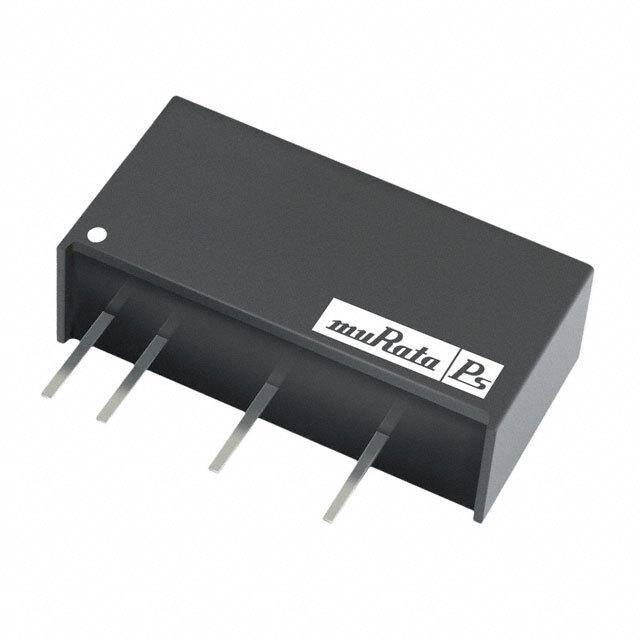
| 描述 | CONV DC/DC 1W 5VIN 5V SIP 5.2KV隔离式DC/DC转换器 1W 5-5V SIP 5.2KV |
| 产品分类 | DC DC ConvertersDC/DC转换器 |
| 品牌 | Murata Power Solutions |
| 产品手册 | |
| 产品图片 |
|
| rohs | RoHS 合规性豁免无铅 / 符合限制有害物质指令(RoHS)规范要求 |
| 产品系列 | 隔离式DC/DC转换器,Murata Power Solutions NMJ0505SACNMJ |
| 数据手册 | |
| 产品型号 | NMJ0505SAC |
| 产品 | Isolated |
| 产品培训模块 | http://www.digikey.cn/PTM/IndividualPTM.page?site=cn&lang=zhs&ptm=21791 |
| 产品目录页面 | |
| 产品种类 | 隔离式DC/DC转换器 |
| 其它名称 | 811-1530-5 |
| 功率(W)-制造系列 | 1W |
| 功率(W)-最大值 | 1W |
| 包装 | 管件 |
| 商标 | Murata Power Solutions |
| 大小/尺寸 | 0.77" 长 x 0.39" 宽 x 0.49" 高(19.6mm x 9.9mm x 12.4mm) |
| 安装类型 | 通孔 |
| 安装风格 | Through Hole |
| 封装 | Tube |
| 封装/外壳 | 7-SIP 模块(4 引线) |
| 封装/箱体尺寸 | SIP |
| 工作温度 | -40°C ~ 60°C |
| 工厂包装数量 | 25 |
| 效率 | 68% |
| 标准包装 | 25 |
| 特性 | - |
| 电压-输入(最大值) | 5.5V |
| 电压-输入(最小值) | 4.5V |
| 电压-输出1 | 5V |
| 电压-输出2 | - |
| 电压-输出3 | - |
| 电压-隔离 | 5.2kV(5200V) |
| 电流-输出(最大值) | 200mA |
| 类型 | 隔离模块 |
| 绝缘电压 | 5.2 kV |
| 输入电压—公称值 | 5 V |
| 输入电压范围 | 4.5 V to 5.5 V |
| 输出功率 | 1 W |
| 输出数 | 1 |
| 输出电压—通道1 | 5 V |
| 输出电流—通道1 | 200 mA |
| 输出端数量 | 1 |
| 输出类型 | Non-Isolated |


PDF Datasheet 数据手册内容提取
NMJ Series www.murata-ps.com 5.2kVDC Isolated 1W DC-DC Converters SELECTION GUIDE Nominal Output Output Ripple & Efficiency Isolation Input MTTF1 Order Code Voltage Voltage Current Noise2 (Min.) Capacitance V V mA mV p-p % pF kHrs NMJ0505SC 5 ±5 ±100 40 60 3.0 4950 NMJ0509SC 5 ±9 ±55 30 64 3.0 3832 NMJ0512SC 5 ±12 ±42 20 65 3.0 2770 NMJ0515SC 5 ±15 ±33 20 65 3.0 1903 NMJ1205SC 12 ±5 ±100 40 60 3.0 3688 FEATURES NMJ1209SC 12 ±9 ±55 30 65 3.0 3029 (cid:132)(cid:3)UL60950 recognised NMJ1212SC 12 ±12 ±42 20 65 3.0 2324 NMJ1215SC 12 ±15 ±33 20 65 3.0 1682 (cid:132)(cid:3)Wide temperature performance at full NMJ0303SAC 3.3 3.3 303 70 65 3.0 13780 1 watt load, –40°C to 85°C NMJ0503SAC 5 3.3 303 60 64 3.0 13460 (cid:132)(cid:3)Single and dual outputs NMJ0505SAC 5 5 200 50 68 3.0 13360 NMJ0509SAC 5 9 111 50 72 3.0 12700 (cid:132)(cid:3)SIP package style NMJ0512SAC 5 12 83 50 71 3.0 11490 (cid:132)(cid:3)5.2kVDC isolation ‘Hi Pot Test’ NMJ0515SAC 5 15 66 50 71 3.0 9980 (cid:132)(cid:3)3V, 5V & 12V input NMJ1205SAC 12 5 200 50 69 3.0 8447 NMJ1209SAC 12 9 111 50 73 3.0 8176 (cid:132)(cid:3)3V, 5V, 9V, 12V and 15V output NMJ1212SAC 12 12 83 50 73 3.0 7660 (cid:132)(cid:3)Internal SMD construction NMJ1215SAC 12 15 66 50 74 3.0 6950 (cid:132)(cid:3)Pin compatible with the CRV1, NMV, MEV1, INPUT CHARACTERISTICS MMV1, MEJ1 series SIP DC-DC converters Parameter Conditions Min. Typ. Max. Units Continuous operation, 3V input types 2.97 3.3 3.63 (cid:132)(cid:3)MTTF up to 13 million hours Voltage range Continuous operation, 5V input types 4.5 5 5.5 V (cid:132)(cid:3)Custom solutions available Continuous operation, 12V input types 10.8 12 13.2 PRODUCT OVERVIEW OUTPUT CHARACTERISTICS Parameter Conditions Min. Typ. Max. Units The NMJ series are dual and single output DC-DC converters in a 7 pin SIP package style Rated Power TA=-40ºC to 85ºC, see derating graph 1 W Voltage Set Point Accuracy See tolerance envelopes offering pin and functionality compatibility with the NMV series SIP DC-DC converters. The NMJ Line regulation High VIN to low VIN 1.0 1.2 %/% 10% load to rated load, xx03 10.0 15.0 series is UL60950 recognized and suitable for applications where safety and miniaturisation Load regulation 10% load to rated load, 0505 7.0 10.0 % are of paramount importance. Isolation barrier Single outputs 10% load to rated load, 0509, 0512, 0515 6.0 10.0 approved for supplementary/reinforced insulation 10% load to rated load, 12xx 5.0 7.0 - see page 2. 10% load to rated load, 5V output types 10.0 15.0 Load regulation 10% load to rated load, 9V output types 6.0 10.0 % Dual outputs 10% load to rated load, 12V output types 6.0 10.0 10% load to rated load, 15V output types 6.0 10.0 Zero Load Power Consumption All types 250 mW ABSOLUTE MAXIMUM RATINGS Lead temperature 1.5mm from case for 10 seconds 260°C Input voltage VIN, NMJ03 types 5V Input voltage VIN, NMJ05 types 7V Input voltage VIN, NMJ12 types 15V 1. Calculated using MIL-HDBK-217 FN2 calculation model with nominal input voltage at full load. 2. See ripple & noise test method. All specifications typical at TA=25°C, nominal input voltage and rated output current unless otherwise specified. For full details go to www.murata-ps.com/rohs www.murata-ps.com/support KDC_NMJ.H02 Page 1 of 6
NMJ Series 5.2kVDC Isolated 1W DC-DC Converters ISOLATION CHARACTERISTICS Parameter Conditions Min. Typ. Max. Units Isolation test voltage Flash tested for 1 second 5200 VDC Resistance Viso= 500VDC 1 GΩ GENERAL CHARACTERISTICS Parameter Conditions Min. Typ. Max. Units Single output 45 Switching frequency kHz Dual output 70 TEMPERATURE CHARACTERISTICS Parameter Conditions Min. Typ. Max. Units Specification All output types, see safety approval section for UL temperature specification -40 85 Storage -55 130 °C Case Temperature above ambient All output types 33 Cooling Free air convection TEMPERATURE DERATING GRAPH 1.5 W)1.0 85ºC er ( w o ut P0.5 Safe Operating Area p ut O 0 -40 0 40 90 Ambient Temperature (ºC) TECHNICAL NOTES ISOLATION VOLTAGE ‘Hi Pot Test’, ‘Flash Tested’, ‘Withstand Voltage’, ‘Proof Voltage’, ‘Dielectric Withstand Voltage’ & ‘Isolation Test Voltage’ are all terms that relate to the same thing, a test voltage, applied for a specified time, across a component designed to provide electrical isolation, to verify the integrity of that isolation. Murata Power Solutions NMJ series of DC-DC converters are all 100% production tested at their stated isolation voltage. This is 5.2kVDC for 1 second. A question commonly asked is, “What is the continuous voltage that can be applied across the part in normal operation?” The NMJ series has been recognized by Underwriters Laboratory to 300Vrms for Supplementary Insulation and 150Vrms for Reinforced Insulation. REPEATED HIGH-VOLTAGE ISOLATION TESTING It is well known that repeated high-voltage isolation testing of a barrier component can actually degrade isolation capability, to a lesser or greater degree depending on materials, construction and environment. We therefore strongly advise against repeated high voltage isolation testing, but if it is absolutely required, that the voltage be reduced by 20% from specified test voltage. SAFETY APPROVAL The NMJ series has been recognised by Underwriters Laboratory (UL) to UL60950 for supplementary insulation up to 300Vrms and reinforced insulation up to 150Vrms at a maximum ambient temperature of 75ºC, measured on the side opposite the pins. File number E151252 applies. RoHS COMPLIANCE INFORMATION This series is compatible with RoHS soldering systems with a peak wave solder temperature of 260ºC for 10 seconds. The pin termination finish on this product series is Tin Plate, Hot Dipped over Matte Tin with Nickel Preplate. The series is backward compatible with Sn/Pb soldering systems. For further information, please visit www.murata-ps.com/rohs www.murata-ps.com/support KDC_NMJ.H02 Page 2 of 6
NMJ Series 5.2kVDC Isolated 1W DC-DC Converters APPLICATION NOTES Minimum load The minimum load to meet datasheet specification is 10% of the full rated load across the specified input voltage range. Lower than 10% minimum loading will result in an increase in output voltage, which may rise to typically double the specified output voltage if the output load falls to less than 5%. Capacitive loading and start up Typical start up times for this series, with a typical input voltage rise time of 2.2μs and output capacitance of 10μF, are shown in the table below. The product series will start into a capacitance of 47μF with an increased start time, however, the maximum recommended output capacitance is 10μF. Typical Start-Up Wave Form Start-up time Start-up time μs μs NMJ0505SC 2530 NMJ0505SAC 1059 NMJ0509SC 7865 NMJ0509SAC 3454 NMJ0512SC 13080 NMJ0512SAC 7980 NMJ0515SC 21560 NMJ0515SAC 11505 NMJ1205SC 2770 NMJ1205SAC 1286 NMJ1209SC 20455 NMJ1209SAC 3548 NMJ1212SC 14475 NMJ1212SAC 7355 NMJ1215SC 22300 NMJ1215SAC 11535 NMJ0303SAC 530 NMJ0503SAC 576 Ripple & Noise Characterisation Method Ripple and noise measurements are performed with the following test configuration. C1 1μF X7R m ultilayer ceramic capacitor, voltage rating to be a minimum of 3 times the output voltage of the DC-DC converter 10μF tantalum capacitor, voltage rating to be a minimum of 1.5 times the output voltage of the DC-DC converter with an ESR of less C2 than 100mΩ at 100 kHz C3 100nF multilayer ceramic capacitor, general purpose R1 450Ω resistor, carbon film, ±1% tolerance R2 50Ω BNC termination T1 3T of the coax cable through a ferrite toroid RLOAD Resistive load to the maximum power rating of the DC-DC converter. Connections should be made via twisted wires Measured values are multiplied by 10 to obtain the specified values. Differential Mode Noise Test Schematic DC/DC Converter OSCILLOSCOPE C1 C2 C3 R1 T1 R2 + + Y INPUT SUPPLY Input Output - - R LOAD www.murata-ps.com/support KDC_NMJ.H02 Page 3 of 6
NMJ Series 5.2kVDC Isolated 1W DC-DC Converters APPLICATION NOTES (continued) Output Ripple Reduction By using the values of inductance and capacitance stated, the output ripple at the rated load is lowered to 5mV p-p max. Component selection Capacitor: It is required that the ESR (Equivalent Series Resistance) should be as low as possible, ceramic types are recommended. The voltage rating should be at least twice (except for 15V output), the rated output voltage of the DC-DC converter. Inductor: The rated current of the inductor should not be less than that of the output of the DC-DC converter. At the rated current, the DC resistance of the inductor should be such that the voltage drop across the inductor is <2% of the rated voltage of the DC-DC converter. The SRF (Self Resonant Frequency) should be >20MHz. L DC Power C Load Source DC Inductor Capacitor L, μH Through Hole SMD C, μF 3.3V single output types 22 22R223C 82223C 4.7 5V single output types 22 22R223C 82223C 4.7 9V single output types 47 22R473C 82473C 2.2 12V single output types 220 22R224C 82224C 0.47 15V single output types 220 22R224C 82224C 0.47 +VOUT L DC C Load Power OV Source DC C Load -VOUT L w Inductor Capacitor L, μH Through Hole SMD C, μF 5V dual output types 22 22R223C 82223C 4.70 9V dual output types 47 22R473C 82473C 2.2 12V dual output types 220 22R224C 82224C 0.47 15V dual output types 220 22R224C 82224C 0.47 www.murata-ps.com/support KDC_NMJ.H02 Page 4 of 6
NMJ Series 5.2kVDC Isolated 1W DC-DC Converters TOLERANCE ENVELOPES The voltage tolerance envelopes show typical load regulation characteristics for this product series. The tolerance envelope is the maximum output voltage variation due to changes in output loading and set point accuracy. 3.3, 5, 9, 12 & 15V output types NMJ0303SAC +10% +9% +6% Typical Load Line +2.5% Typical Load Line +1% +1% utput Voltage VNOM --47%.5% put Voltage VNO-M7% -7% O ut O -15% 10 25 50 75 100 10 25 50 75 100 Output Load Current (%) Output Load Current (%) www.murata-ps.com/support KDC_NMJ.H02 Page 5 of 6
NMJ Series 5.2kVDC Isolated 1W DC-DC Converters PACKAGE SPECIFICATIONS MECHANICAL DIMENSIONS PIN CONNECTIONS 19.50±0.25 [0.768±0.010] Dual Output Single Output Pin Function Pin Function 9.80±0.25 [0.386±0.010] 1 +VIN 1 +VIN 2 -VIN 2 -VIN 5 -VOUT 5 -VOUT 6 OV 7 +VOUT NMJXXXXSC 7 +VOUT 12.50±0.25 [0.492±0.010] XYCYWWUS 0.40 [0.016] MIN S TUBE OUTLINE DIMENSIONS 6.00 14.20 (0.559) 4.10±0.5 [0.161±0.020] (0.236) 0.50±0.05 [0.020±0.002] 2.54 [0.100] 5.08 [0.200] 5.00 (0.197) 0.25±0.05 [0.010±0.002] 1 2 5 6* 7 5.20 (0.205) (2.84 [0.112]) 2.54 [0.100] 1.50 (0.059) (2.13 [0.084]) 15.24 [0.600] 0.006±0.024 (0.15±0.60) * Pin not fitted on single output variants. Weight: 4.3g All dimensions in mm (inches) Controlling dimension is mm. Unless otherwise stated all dimensions in mm ±0.5mm (inches ±0.02). All pins on a 2.54 (0.100) pitch and within ±0.1 (0.004) of true position from pin 1 at seating plane ‘S’ Tube length : 525mm±2mm (20.669±0.079). Tube Quantity : 25 RECOMMENDED FOOTPRINT DETAILS Single Output Package: Dual Output Package: x4 HOLES 2.54 [0.100] Ø11..1050 [Ø00..004359] 2.54 [0.100] Ø1.0x85 H[OØLE0S.042] 0.93 0.036 2.54 [0.100] 2.54 [0.100] All dimensions in mm (inches) Controlling dimension is mm. This product is subject to the following operating requirements and the Life and Safety Critical Application Sales Policy: Refer to: http://www.murata-ps.com/requirements/ Murata Power Solutions, Inc. makes no representation that the use of its products in the circuits described herein, or the use of other technical information contained herein, will not infringe upon existing or future patent rights. The descriptions contained herein do not imply the granting of licenses to make, use, or sell equipment constructed in accordance therewith. Specifications are subject to change without notice. © 2018 Murata Power Solutions, Inc. www.murata-ps.com/support KDC_NMJ.H02 Page 6 of 6
Mouser Electronics Authorized Distributor Click to View Pricing, Inventory, Delivery & Lifecycle Information: M urata: NMJ0512SC NMJ1209SC NMJ0515SC NMJ1205SC NMJ0509SC NMJ1215SC NMJ0505SC NMJ1212SC NMJ1209SAC NMJ0505SAC NMJ0503SAC NMJ0512SAC NMJ0515SAC NMJ0509SAC NMJ1205SAC NMJ0303SAC NMJ1215SAC NMJ1212SAC