ICGOO在线商城 > 传感器,变送器 > 温度传感器 - NTC 热敏电阻器 > NCP21XQ471J03RA

 Datasheet下载
- 型号: NCP21XQ471J03RA
- 制造商: Murata
- 库位|库存: xxxx|xxxx
- 要求:
| 数量阶梯 | 香港交货 | 国内含税 |
| +xxxx | $xxxx | ¥xxxx |
查看当月历史价格
查看今年历史价格
NCP21XQ471J03RA产品简介:
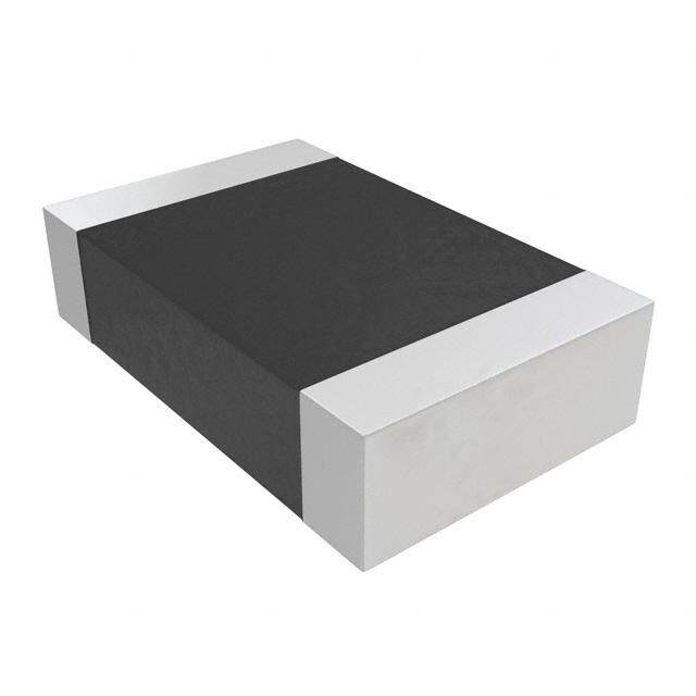
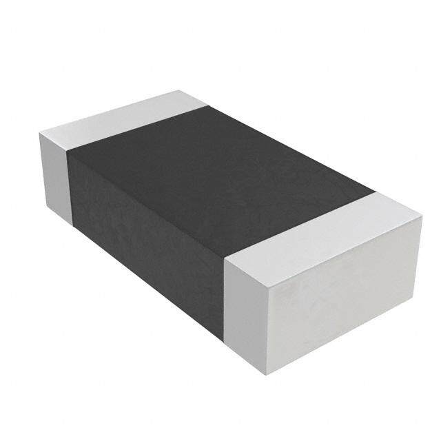
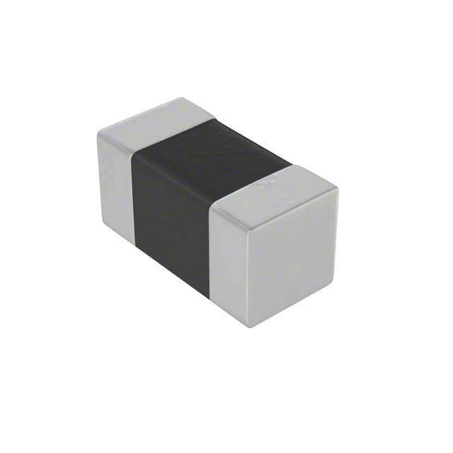
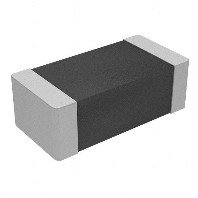
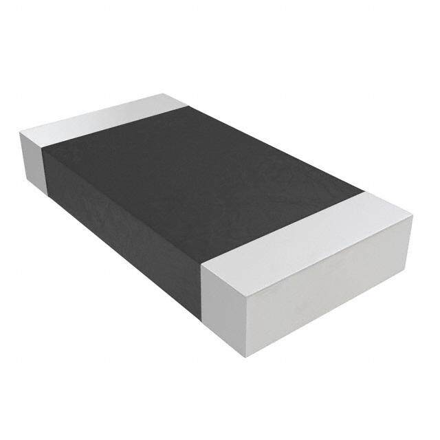
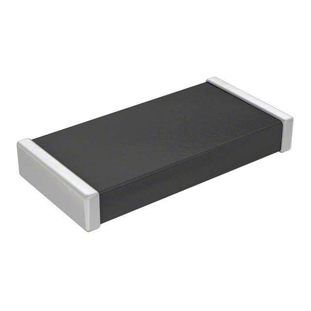
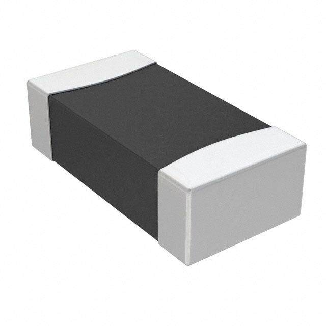
ICGOO电子元器件商城为您提供NCP21XQ471J03RA由Murata设计生产,在icgoo商城现货销售,并且可以通过原厂、代理商等渠道进行代购。 NCP21XQ471J03RA价格参考。MurataNCP21XQ471J03RA封装/规格:温度传感器 - NTC 热敏电阻器, NTC Thermistor 470 0805 (2012 Metric)。您可以下载NCP21XQ471J03RA参考资料、Datasheet数据手册功能说明书,资料中有NCP21XQ471J03RA 详细功能的应用电路图电压和使用方法及教程。
NCP21XQ471J03RA 是由 Murata Electronics North America 生产的一款 NTC(负温度系数)热敏电阻器,属于温度传感器类别。以下是其主要应用场景:

 1. 温度监测与控制
   - 家用电器:用于冰箱、空调、微波炉等设备中监测和控制温度,确保设备在安全的工作温度范围内运行。
   - 工业设备:在工业自动化系统中,用于监控电机、变压器和其他发热部件的温度,防止过热损坏。
   - 医疗设备:如血液分析仪、恒温培养箱等需要精确温度控制的设备。

 2. 过热保护
   - 电源模块:在开关电源、适配器等电力电子设备中,用作过热保护元件,当温度超过设定值时触发保护机制。
   - 电池管理系统 (BMS):监测电池组温度,避免因过热导致的安全隐患,特别是在电动车和便携式电子设备中。

 3. 温度补偿
   - 精密电路:在高频振荡器、晶体振荡器等电路中,用于补偿温度变化对电路性能的影响。
   - 传感器校准:与其他传感器配合使用,提供温度补偿功能以提高测量精度。

 4. 消费电子产品
   - 智能手机和平板电脑:检测设备内部温度,防止过热影响性能或造成损坏。
   - 打印机和扫描仪:监控加热元件(如定影单元)的温度,确保打印质量并延长设备寿命。

 5. 汽车电子
   - 发动机管理:用于监测冷却液温度、进气温度等关键参数,优化发动机性能。
   - 电动车电池管理:实时监测电池组温度,确保电池在最佳工作温度范围内运行。

 特性优势
- 高精度:能够提供高精度的温度测量,适用于对温度敏感的应用场景。
- 快速响应:对温度变化反应迅速,适合动态温度监测需求。
- 可靠性强:具有良好的稳定性和耐用性,能够在恶劣环境下长期工作。

总之,NCP21XQ471J03RA 凭借其优异的性能和稳定性,广泛应用于需要精确温度监测和控制的各种领域。
| 参数 | 数值 |
| 25°C时欧姆阻值 | 470 |
| B0/50 | - |
| B25/100 | 3706K |
| B25/50 | 3650K |
| B25/75 | - |
| B25/85 | 3693K |
| B值容差 | ±3% |
| 产品目录 | |
| 描述 | THERMISTOR 470 OHM NTC 0805 SMD热敏电阻 - NTC 470 OHM 5% |
| 产品分类 | 热敏电阻 - NTC热敏电阻 - NTC |
| 品牌 | Murata Electronics North America |
| 产品手册 | |
| 产品图片 |
|
| rohs | 符合RoHS无铅 / 符合限制有害物质指令(RoHS)规范要求 |
| 产品系列 | Murata Electronics NCP21XQ471J03RANCP21 |
| 数据手册 | |
| 产品型号 | NCP21XQ471J03RA |
| 产品培训模块 | http://www.digikey.cn/PTM/IndividualPTM.page?site=cn&lang=zhs&ptm=11491 |
| 产品目录绘图 |
|
| 产品目录页面 | |
| 产品种类 | 热敏电阻 - NTC |
| 其它名称 | 490-2455-2 |
| 功率-最大值 | 200mW |
| 功率额定值 | 200 mW |
| 包装 | 带卷 (TR) |
| 商标 | Murata Electronics |
| 安装类型 | 表面贴装 |
| 容差 | 5 % |
| 封装 | Reel |
| 封装/外壳 | 0805(2012 公制) |
| 封装/箱体 | 0805 |
| 尺寸 | 1.25 mm W x 2 mm L x 1.25 mm H |
| 工作温度 | -40°C ~ 125°C |
| 工作温度范围 | - 40 C to + 125 C |
| 工厂包装数量 | 4000 |
| 标准包装 | 4,000 |
| 电流额定值 | 2 mA |
| 电阻 | 470 Ohms |
| 电阻容差 | ±5% |
| 端接类型 | SMD/SMT |
| 类型 | NTC |
| 系列 | NCP |
| 长度-引线 | - |


PDF Datasheet 数据手册内容提取
R44E.pdf Mar.6,2020 NTC Thermistors
!Note (cid:129) Please read rating and !CAUTION (for storage, operating, rating, soldering, mounting and handling) in this catalog to prevent smoking and/or burning, etc. R44E.pdf (cid:129) This catalog has only typical specifications. Therefore, please approve our product specifications or transact the approval sheet for product specifications before ordering. Mar.6,2020 EU RoHS Compliant (cid:70)(cid:3)(cid:5)(cid:42)(cid:42)(cid:3)(cid:50)(cid:38)(cid:35)(cid:3)(cid:46)(cid:48)(cid:45)(cid:34)(cid:51)(cid:33)(cid:50)(cid:49)(cid:3)(cid:39)(cid:44)(cid:3)(cid:50)(cid:38)(cid:39)(cid:49)(cid:3)(cid:33)(cid:31)(cid:50)(cid:31)(cid:42)(cid:45)(cid:37)(cid:3)(cid:33)(cid:45)(cid:43)(cid:46)(cid:42)(cid:55)(cid:3) (cid:53)(cid:39)(cid:50)(cid:38)(cid:3)(cid:9)(cid:25)(cid:3)(cid:22)(cid:45)(cid:12)(cid:23)(cid:64) (cid:70)(cid:3)(cid:9)(cid:25)(cid:3)(cid:22)(cid:45)(cid:12)(cid:23)(cid:3)(cid:39)(cid:49)(cid:3)(cid:159)(cid:50)(cid:38)(cid:35)(cid:3)(cid:9)(cid:51)(cid:48)(cid:45)(cid:46)(cid:35)(cid:31)(cid:44)(cid:3)(cid:8)(cid:39)(cid:48)(cid:35)(cid:33)(cid:50)(cid:39)(cid:52)(cid:35)(cid:3) (cid:124)(cid:122)(cid:123)(cid:123)(cid:71)(cid:128)(cid:127)(cid:71)(cid:9)(cid:25)(cid:3)(cid:45)(cid:44)(cid:3)(cid:50)(cid:38)(cid:35)(cid:3)(cid:22)(cid:35)(cid:49)(cid:50)(cid:48)(cid:39)(cid:33)(cid:50)(cid:39)(cid:45)(cid:44)(cid:3)(cid:45)(cid:36)(cid:3)(cid:50)(cid:38)(cid:35)(cid:3) (cid:25)(cid:49)(cid:35)(cid:3)(cid:45)(cid:36)(cid:3)(cid:7)(cid:35)(cid:48)(cid:50)(cid:31)(cid:39)(cid:44)(cid:3)(cid:12)(cid:31)(cid:56)(cid:31)(cid:48)(cid:34)(cid:45)(cid:51)(cid:49)(cid:3)(cid:23)(cid:51)(cid:32)(cid:49)(cid:50)(cid:31)(cid:44)(cid:33)(cid:35)(cid:49)(cid:3)(cid:39)(cid:44)(cid:3) (cid:9)(cid:42)(cid:35)(cid:33)(cid:50)(cid:48)(cid:39)(cid:33)(cid:31)(cid:42)(cid:3)(cid:31)(cid:44)(cid:34)(cid:3)(cid:9)(cid:42)(cid:35)(cid:33)(cid:50)(cid:48)(cid:45)(cid:44)(cid:39)(cid:33)(cid:3)(cid:9)(cid:47)(cid:51)(cid:39)(cid:46)(cid:43)(cid:35)(cid:44)(cid:50)(cid:64)(cid:159)(cid:3) (cid:70)(cid:3)For(cid:3)(cid:43)(cid:45)(cid:48)(cid:35)(cid:3)(cid:34)(cid:35)(cid:50)(cid:31)(cid:39)(cid:42)(cid:49)(cid:65)(cid:3)(cid:46)(cid:42)(cid:35)(cid:31)(cid:49)(cid:35)(cid:3)(cid:48)(cid:35)(cid:36)(cid:35)r(cid:3)(cid:50)o(cid:3)(cid:45)ur(cid:3)(cid:53)(cid:35)(cid:32)(cid:3) (cid:46)(cid:31)(cid:37)(cid:35)(cid:65)(cid:3)(cid:159)(cid:17)(cid:51)(cid:48)(cid:31)(cid:50)(cid:31)(cid:158)(cid:49)(cid:3)(cid:5)(cid:46)(cid:46)(cid:48)(cid:45)(cid:31)(cid:33)(cid:38)(cid:3)(cid:36)(cid:45)(cid:48)(cid:3)(cid:9)(cid:25)(cid:3)(cid:22)(cid:45)(cid:12)(cid:23)(cid:159)(cid:3) (cid:72)(cid:38)(cid:50)(cid:50)(cid:46)(cid:49)(cid:66)(cid:71)(cid:71)(cid:53)(cid:53)(cid:53)(cid:64)(cid:43)(cid:51)(cid:48)(cid:31)(cid:50)(cid:31)(cid:64)(cid:33)(cid:45)(cid:43)(cid:71)(cid:35)(cid:44)(cid:81)(cid:35)(cid:51)(cid:71)(cid:49)(cid:51)(cid:46)(cid:46)(cid:45)(cid:48)(cid:50)(cid:71) (cid:33)(cid:45)(cid:43)(cid:46)(cid:42)(cid:39)(cid:31)(cid:44)(cid:33)(cid:35)(cid:71)(cid:48)(cid:45)(cid:38)(cid:49)(cid:74)(cid:64)(cid:3)
!Note (cid:129) Please read rating and !CAUTION (for storage, operating, rating, soldering, mounting and handling) in this catalog to prevent smoking and/or burning, etc. R44E.pdf (cid:129) This catalog has only typical specifications. Therefore, please approve our product specifications or transact the approval sheet for product specifications before ordering. Mar.6,2020 1 Contents Product specifications are as of February 2020. 2 Part Numbering p2 Basic Characteristics p5 1 Temperature Sensor and Compensation 0201 (0603) Size p6 3 2 Temperature Sensor and Compensation 0402 (1005) Size/NCP Series p7 Temperature Sensor and Compensation 0402 (1005) Size/NCU Series p9 3 Temperature Sensor and Compensation 0603 (1608) Size/NCP Series p10 4 Temperature Sensor and Compensation 0603 (1608) Size/NCU Series p12 Temperature Sensor and Compensation Chip Type Standard Land Pattern Dimensions p13 Temperature Sensor and Compensation Chip Type Temperature Characteristics (Center Value) p14 Temperature Sensor and Compensation Chip Type 5 !Caution/Notice p17 Temperature Sensor and Compensation Chip Type Package p21 4 Temperature Sensor Thermo String Cooper Wire Type p23 Temperature Sensor Thermo String 6 Nickel Copper Wire Type p24 Temperature Sensor Thermo String Type Specifications and Test Methods p25 5 Temperature Sensor Lead Type p27 Temperature Sensor Lead Type Specifications and Test Methods p28 6 Temperature Sensor Lead Insulation Type p29 Temperature Sensor Lead Insulation Type Specifications and Test Methods p30 Temperature Sensor Thermo String/Lead Type Temperature Characteristics (Center Value) p31 Temperature Sensor Thermo String/Lead Type !Caution/Notice p32 Temperature Sensor Thermo String/Lead Type Package p34 Please check the MURATA website (https://www.murata.com/) if you cannot find a part number in this catalog.
!Note (cid:129) Please read rating and !CAUTION (for storage, operating, rating, soldering, mounting and handling) in this catalog to prevent smoking and/or burning, etc. R44E.pdf (cid:129) This catalog has only typical specifications. Therefore, please approve our product specifications or transact the approval sheet for product specifications before ordering. Mar.6,2020 o Part Numbering NTC Thermistors for Temp. Sensor and Compensation Chip Type (Part Number) NC P 18 XH 103 J 03 RB 1 2 3 4 5 6 7 8 1Product ID 5Resistance Product ID Expressed by three-digit alphanumerics. The unit is ohm (Ω). The first and second figures are significant digits, and the third NC NTC Thermistors Chip Type figure expresses the number of zeros that follow the two figures. 2Series Ex. Code Resistance Code Series 102 1kΩ P Plated Termination Series 103 10kΩ U High Reliability Series 104 100kΩ 3Dimensions (L x W) 6Resistance Tolerance Code Dimensions (L x W) EIA Code Resistance Tolerance 03 0.60 x 0.30mm 0201 D ±0.5% 15 1.00 x 0.50mm 0402 F ±1% 18 1.60 x 0.80mm 0603 E ±3% 21 2.00 x 1.25mm 0805 J ±5% 4Temperature Characteristics 7Individual Specifications Code Temperature Characteristics Structures and other specifications are expressed by two figures. XC Nominal B-Constant 3100–3149K Ex. Code Individual Specifications XF Nominal B-Constant 3250–3299K 03/05/10/12/60 Standard Type XH Nominal B-Constant 3350–3399K pS Automotive Type XM Nominal B-Constant 3500–3549K XQ Nominal B-Constant 3650–3699K 8Packaging XV Nominal B-Constant 3900–3949K Code Packaging XW Nominal B-Constant 3950–3999K RA Plastic Taping 4mm Pitch (4000 pcs.) WB Nominal B-Constant 4050–4099K RB Paper Taping 4mm Pitch (4000 pcs.) WD Nominal B-Constant 4150–4199K RC Paper Taping 2mm Pitch (10000 pcs.) WF Nominal B-Constant 4250–4299K RL Paper Taping 2mm Pitch (15000 pcs.) WL Nominal B-Constant 4450–4499K WM Nominal B-Constant 4500–4549K 2
!Note (cid:129) Please read rating and !CAUTION (for storage, operating, rating, soldering, mounting and handling) in this catalog to prevent smoking and/or burning, etc. R44E.pdf (cid:129) This catalog has only typical specifications. Therefore, please approve our product specifications or transact the approval sheet for product specifications before ordering. Mar.6,2020 NTC Thermistor for Temperature Sensor Thermo String Type (Part Number) NXF T 15 XH 103 F A 2 B 025 1 2 3 4 5 6 7 8 9 : 1Product ID 7Lead Wire Type Product ID Code Lead Wire Type NXF NTC Thermistors Sensor Thermo String Type A ø0.3mm Copper Lead Wire with Polyurethane Coat E ø0.3mm Nickel Copper Lead Wire with Modified Polyester Coat 2Individual Specifications Code Individual Specifications 8Shape of the Lead Wire Kink T Commercial Type Code Shape of the Lead Wire Kink 1 Twisted Lead Wire Type 3Chip Dimensions 2 Standard Type (Cooper Wire Type) Code Dimensions (L x T) EIA A Standard Type (Nickel Copper Wire Type) 15 1.00 x 0.50mm 0402 9Packaging 4Temperature Characteristics Code Packaging Code Temperature Characteristics B Bulk XH Nominal B-Constant 3350–3399K XM Nominal B-Constant 3500–3549K :Dimensions (Full Length) XV Nominal B-Constant 3900–3949K Code Dimensions (Full Length) WB Nominal B-Constant 4050–4099K 021 21mm WF Nominal B-Constant 4250–4299K 025 25mm 030 30mm 5Resistance 035 35mm Expressed by three figures. The unit is (Ω). The first and second 040 40mm figures are significant digits, and the third figure expresses the 045 45mm number of zeros that follow the two figures. 050 50mm Ex. Code Resistance 060 60mm 103 10kΩ 070 70mm 473 47kΩ 080 80mm 104 100kΩ 090 90mm 6Resistance Tolerance 100 100mm 110 110mm Code Resistance Tolerance 120 120mm F ±1% 130 130mm E ±3% 140 140mm 150 150mm 3
!Note (cid:129) Please read rating and !CAUTION (for storage, operating, rating, soldering, mounting and handling) in this catalog to prevent smoking and/or burning, etc. R44E.pdf (cid:129) This catalog has only typical specifications. Therefore, please approve our product specifications or transact the approval sheet for product specifications before ordering. Mar.6,2020 NTC Thermistor for Temperature Sensor/Lead Type (Part Number) NXR T 15 XH 103 F A 1 B 040 1 2 3 4 5 6 7 8 9 : 1Product ID 7Lead Wire Type Product ID Code Lead Wire Type NXR NTC Thermistor Sensor/Lead Type Lead Type: ø0.4mm Copper-clad Fe Wire, Tinned A Lead Insulation Type: ø0.46mm Cu Wire with Coat 2Individual Specifications Code Individual Specifications 8Shape of the Lead Wire T Commercial Type Code Shape of the Lead Wire 1 Lead Spacing 2.5mm 3Chip Dimensions 3 Lead Spacing 5.0mm Code Dimensions (L x T) 5 Lead Spacing 2.5mm (Insulation Type) 15 1.00 x 0.50mm 9Packaging 4Temperature Characteristics Code Packaging Code Temperature Characteristics A Ammo Pack Taping XH Nominal B-Constant 3350–3399K B Bulk XM Nominal B-Constant 3500–3549K XV Nominal B-Constant 3900–3949K :Dimensions (Full Length) WB Nominal B-Constant 4050–4099K Code Lead Type Lead Insulation Type WF Nominal B-Constant 4250–4299K 010 10mm – 020 20mm – 5Resistance 025 – 25mm Expressed by three figures. The unit is (Ω). The first and second 030 30mm 30mm figures are significant digits, and the third figure expresses the 035 – 35mm number of zeros that follow the two figures. 040 40mm 40mm Ex. Code Resistance 045 – 45mm 202 2.0kΩ 050 50mm 50mm 103 10kΩ 016 16mm (Taping Type) – 104 100kΩ 6Resistance Tolerance Code Resistance Tolerance F ±1% E ±3% J ±5% 4
!Note (cid:129) Please read rating and !CAUTION (for storage, operating, rating, soldering, mounting and handling) in this catalog to prevent smoking and/or burning, etc. R44E.pdf (cid:129) This catalog has only typical specifications. Therefore, please approve our product specifications or transact the approval sheet for product specifications before ordering. Mar.6,2020 Basic Characteristics Basic Characteristics 1. Zero-power Resistance of Thermistor: R R=R0 expB (1/T–1/T0) ......................................... (1) Resistance vs. Temperature R: Resistance in ambient temperature T (K) 102 (K: absolute temperature) 5 R0: Resistance in ambient temperature T0 (K) R2 / B: B-Constant of Thermistor R s, stic101 eri ct 2. B-Constant ara h as (1) formula C B= n (R/R0) / (1/T–1/T0) ature 1 er p m e T 3. Thermal Dissipation Constant e vs. 10–1 When electric power P (mW) is spent in ambient nc B=3450 a temperature T1 and thermistor temperature rises T2, sist BB==34910000 e the formula is as follows R P=C (T2–T1) 10–2 –20 0 20 40 60 80 100120 C: Thermal dissipation constant (mW/°C) Temperature (°C) Thermal dissipation constant is varied with dimensions, measurement conditions, etc. 4. Thermal Time Constant Thermal Time Constant Period in which the thermistor's temperature will change 63.2% of its temperature difference from ambient temperature T0 (°C) to T1 (°C). T1 X e ur at er p m e T 63.2% T0 Time Performance Item Condition Resistance Measured by zero-power in specified ambient temperature. Calculated between two specified ambient temperatures by the next formula. T and T0 is absolute temperature (K). B-Constant B = n (R/R0) 1/T–1/T0 Shows necessary electric power that Thermistor's temperature rises 1°C by self-heating. It is calculated by the next formula (mW/°C). Thermal Dissipation Constant P C = T–T0 Maximum Operating Current It is possible to keep the thermistor's temperature rising max. 0.1°C. Please inquire about test conditions and ratings. 5
!Note (cid:129) Please read rating and !CAUTION (for storage, operating, rating, soldering, mounting and handling) in this catalog to prevent smoking and/or burning, etc. R44E.pdf (cid:129) This catalog has only typical specifications. Therefore, please approve our product specifications or transact the approval sheet for product specifications before ordering. Mar.6,2020 NTC Thermistors 1 Temperature Sensor and Compensation 0201 (0603) Size Chip NTC Thermistors' Ni barrier termination provides 3 0 excellent solderability and their unique construction 0±0. 3 offers high stability in the application's environment. 0. 0.15±0.05 0.15±0.05 Features 0.60±0.03 1. Excellent solderability and high stability in the application's environment 03 0. 2. Excellent long-term stability 30± 0. 3. High accuracy in resistance and B-Constant 4. Reflow soldering possible Electrode (Ag System + Ni Plating + Sn Plating) (in mm) 5. NCP series are recognized by UL/cUL. (UL1434, File No.E137188) Detailed are accessable from the following URL. Applications https://www.murata.com/en-global/products/thermistor/ntc/ncp 1. Temperature compensation for transistors, ICs, and crystal oscillators in mobile communications 2. Temperature sensor for rechargeable batteries Resistance B-Constant B-Constant B-Constant B-Constant Maximum Operating Maximum Typical Dissipation Part Number (25°C) (25-50°C) (25-80°C) (25-85°C) (25-100°C) Current (25°C) Voltage Constant (25°C) (ohm) (K) (Reference Value) (K) (Reference Value) (K) (Reference Value) (K) (mA) (V) (mW/°C) NCP03XM102p05RL 1.0k 3500 ±1% 3539 3545 3560 0.316 5 1 NCP03XM152p05RL 1.5k 3500 ±1% 3539 3545 3560 0.258 5 1 NCP03XM222p05RL 2.2k 3500 ±1% 3539 3545 3560 0.213 5 1 NCP03XM332p05RL 3.3k 3500 ±1% 3539 3545 3560 0.174 5 1 NCP03XM472p05RL 4.7k 3500 ±1% 3539 3545 3560 0.146 5 1 NCP03XH682p05RL 6.8k 3380 ±1% 3428 3434 3455 0.121 5 1 NCP03XH103F05RL 10k ±1% 3380 ±1% 3428 3434 3455 0.100 5 1 NCP03XH103p05RL 10k 3380 ±1% 3428 3434 3455 0.100 5 1 NCP03XV103p05RL 10k 3900 ±1% 3930 3934 3944 0.100 5 1 NCP03XH153p05RL 15k 3380 ±1% 3428 3434 3455 0.082 5 1 NCP03XH223F05RL 22k ±1% 3380 ±1% 3428 3434 3455 0.067 5 1 NCP03XH223p05RL 22k 3380 ±1% 3428 3434 3455 0.067 5 1 NCP03WF333p05RL 33k 4250 ±1% 4303 4311 4334 0.055 5 1 NCP03WB473F05RL 47k ±1% 4050 ±1% 4101 4108 4131 0.046 5 1 NCP03WB473p05RL 47k 4050 ±3% 4101 4108 4131 0.046 5 1 NCP03WL473p05RL 47k 4485 ±1% 4537 4543 4557 0.046 5 1 NCP03WF683F05RL 68k ±1% 4250±1% 4303 4311 4334 0.038 5 1 NCP03WF683p05RL 68k 4250 ±1% 4303 4311 4334 0.038 5 1 NCP03WL683p05RL 68k 4485 ±1% 4537 4543 4557 0.038 5 1 NCP03WF104F05RL 100k ±1% 4250 ±1% 4303 4311 4334 0.032 5 1 NCP03WF104p05RL 100k 4250 ±1% 4303 4311 4334 0.032 5 1 NCP03WL104p05RL 100k 4485 ±1% 4537 4543 4557 0.032 5 1 NCP03WL154p05RL 150k 4485 ±1% 4537 4543 4557 0.026 5 1 NCP03WL224p05RL 220k 4485 ±1% 4537 4543 4557 0.021 5 1 NCP03WF474F05RL 470k ±1% 4250±1% 4303 4311 4334 0.015 5 1 p is filled with resistance tolerance codes (E: ±3%, J: ±5%). Operating Temperature Range: -40°C to +125°C 6
!Note (cid:129) Please read rating and !CAUTION (for storage, operating, rating, soldering, mounting and handling) in this catalog to prevent smoking and/or burning, etc. R44E.pdf (cid:129) This catalog has only typical specifications. Therefore, please approve our product specifications or transact the approval sheet for product specifications before ordering. Mar.6,2020 NTC Thermistors Temperature Sensor and Compensation 0402 (1005) Size/NCP Series Chip NTC Thermistors' Ni barrier termination provides 5 excellent solderability and their unique construction 0.0 5± 2 offers high stability in the application's environment. 0. 0.25±0.10 0.25±0.10 Features 1.0±0.05 1. Excellent solderability and high stability in the application's environment 5 0 0. 2. Excellent long-term stability 5± 0. 3. High accuracy in resistance and B-Constant 4. Reflow soldering possible Electrode (Ag System + Ni Plating + Sn Plating) (in mm) 5. Same B-constant in the same resistance in the two sizes (0603 size/0402 size) Downsize is easy for design. Detailed are accessable from the following URL. 6. NCP series are recognized by UL/cUL. https://www.murata.com/en-global/products/thermistor/ntc/ncp (UL1434, File No.E137188) Applications 1. Temperature compensation for transistors, ICs, and crystal oscillators in mobile communications 2. Temperature sensor for rechargeable batteries 3. Temperature compensation of LCD 4. Temperature compensation in general use of electric circuits Resistance B-Constant B-Constant B-Constant B-Constant Maximum Operating Maximum Typical Dissipation Part Number (25°C) (25-50°C) (25-80°C) (25-85°C) (25-100°C) Current (25°C) Voltage Constant (25°C) (ohm) (K) (Reference Value) (K) (Reference Value) (K) (Reference Value) (K) (mA) (V) (mW/°C) NCP15XM221p03RC 220 3500 ±3% 3539 3545 3560 0.674 5 1 NCP15XM331p03RC 330 3500 ±3% 3539 3545 3560 0.550 5 1 NCP15XQ471p03RC 470 3650 ±2% 3688 3693 3706 0.609 5 1 NCP15XQ681p03RC 680 3650 ±3% 3688 3693 3706 0.383 5 1 NCP15XQ102p03RC 1.0k 3650 ±2% 3688 3693 3706 0.316 5 1 NCP15XW152p03RC 1.5k 3950 ±3% 3982 3987 3998 0.258 5 1 NCP15XW222p03RC 2.2k 3950 ±3% 3982 3987 3998 0.213 5 1 NCP15XW332p03RC 3.3k 3950 ±3% 3982 3987 3998 0.174 5 1 NCP15XM472p03RC 4.7k 3500 ±2% 3539 3545 3560 0.146 5 1 NCP15XW472p03RC 4.7k 3950 ±3% 3982 3987 3998 0.146 5 1 NCP15XW682p03RC 6.8k 3950 ±3% 3982 3987 3998 0.121 5 1 NCP15XH103D03RC 10k ±0.5% 3380 ±0.7% 3428 3434 3455 0.100 5 1 NCP15XH103F03RC 10k ±1% 3380 ±1% 3428 3434 3455 0.100 5 1 NCP15XH103p03RC 10k 3380 ±1% 3428 3434 3455 0.100 5 1 NCP15XV103p03RC 10k 3900 ±3% 3930 3934 3944 0.100 5 1 NCP15XW153p03RC 15k 3950 ±3% 3982 3987 3998 0.082 5 1 NCP15XW223p03RC 22k 3950 ±3% 3982 3987 3998 0.067 5 1 NCP15WL223p03RC 22k 4485 ±1% 4537 4543 4557 0.067 5 1 NCP15WB333p03RC 33k 4050 ±3% 4101 4108 4131 0.055 5 1 NCP15WL333p03RC 33k 4485 ±1% 4537 4543 4557 0.055 5 1 NCP15WB473D03RC 47k ±0.5% 4050 ±0.5% 4101 4108 4131 0.046 5 1 NCP15WB473F03RC 47k ±1% 4050 ±1% 4101 4108 4131 0.046 5 1 NCP15WB473p03RC 47k 4050 ±1% 4101 4108 4131 0.046 5 1 NCP15WL473p03RC 47k 4485 ±1% 4537 4543 4557 0.046 5 1 p is filled with resistance tolerance codes (E: ±3%, J: ±5%). Operating Temperature Range: -40°C to +125°C Continued on the following page. 7
!Note (cid:129) Please read rating and !CAUTION (for storage, operating, rating, soldering, mounting and handling) in this catalog to prevent smoking and/or burning, etc. R44E.pdf (cid:129) This catalog has only typical specifications. Therefore, please approve our product specifications or transact the approval sheet for product specifications before ordering. Mar.6,2020 Continued from the preceding page. Resistance B-Constant B-Constant B-Constant B-Constant Maximum Operating Maximum Typical Dissipation Part Number (25°C) (25-50°C) (25-80°C) (25-85°C) (25-100°C) Current (25°C) Voltage Constant (25°C) (ohm) (K) (Reference Value) (K) (Reference Value) (K) (Reference Value) (K) (mA) (V) (mW/°C) NCP15WD683p03RC 68k 4150 ±3% 4201 4209 4232 0.038 5 1 NCP15WL683p03RC 68k 4485 ±1% 4537 4543 4557 0.038 5 1 NCP15WF104D03RC 100k ±0.5% 4250 ±0.5% 4303 4311 4334 0.032 5 1 NCP15WF104F03RC 100k ±1% 4250 ±1% 4303 4311 4334 0.032 5 1 NCP15WF104p03RC 100k 4250 ±1% 4303 4311 4334 0.032 5 1 2 NCP15WL104p03RC 100k 4485 ±1% 4537 4543 4557 0.032 5 1 NCP15WL154p03RC 150k 4485 ±1% 4537 4543 4557 0.026 5 1 NCP15WM154p03RC 150k 4500 ±3% 4571 4582 4614 0.026 5 1 NCP15WM224p03RC 220k 4500 ±3% 4571 4582 4614 0.021 5 1 NCP15WM474p03RC 470k 4500 ±3% 4571 4582 4614 0.015 5 1 p is filled with resistance tolerance codes (E: ±3%, J: ±5%). Operating Temperature Range: -40°C to +125°C 8
!Note (cid:129) Please read rating and !CAUTION (for storage, operating, rating, soldering, mounting and handling) in this catalog to prevent smoking and/or burning, etc. R44E.pdf (cid:129) This catalog has only typical specifications. Therefore, please approve our product specifications or transact the approval sheet for product specifications before ordering. Mar.6,2020 NTC Thermistors Temperature Sensor and Compensation 0402 (1005) Size/NCU Series Chip NTC Thermistors have Ni barrier termination, 5 provide excellent solderability and offer high 0.0 5± 2 stability in environment due to unique inner 0. construction. 0.25±0.10 0.25±0.10 This is new series, available market where request 1.0±0.05 the high reliability for wide temperature sensing and compensation. 5 0 0. 5± Features 0. 1. Excellent solderability and high stability in the Electrode (Cu System + Ni Plating + Sn Plating) (in mm) application's environment 2. Excellent long-term stability 3. High accuracy in resistance and B-Constant Detailed are accessable from the following URL. 4. Reflow soldering possible https://www.murata.com/en-global/products/thermistor/ntc/ncu 5. Same B-constant in the same resistance in the two sizes (0603 size/0402 size) Downsize is easy for design. 6. NCU series are recognized by UL/cUL. (UL1434, File No.E137188) Applications 1. Temperature compensation for transistors, ICs, and crystal oscillators in mobile communications 2. Temperature sensor for rechargeable batteries 3. Temperature compensation of LCD 4. Temperature compensation in general use of electric circuits Resistance B-Constant B-Constant B-Constant B-Constant Maximum Operating Maximum Typical Dissipation Part Number (25°C) (25-50°C) (25-80°C) (25-85°C) (25-100°C) Current (25°C) Voltage Constant (25°C) (ohm) (K) (Reference Value) (K) (Reference Value) (K) (Reference Value) (K) (mA) (V) (mW/°C) NCU15XH103D60RC 10k ±0.5% 3380 ±0.7% 3428 3434 3455 0.100 5 1 NCU15XH103F60RC 10k ±1% 3380 ±1% 3428 3434 3455 0.100 5 1 NCU15XH103p60RC 10k 3380 ±1% 3428 3434 3455 0.100 5 1 NCU15WB473D60RC 47k ±0.5% 4050 ±0.5% 4101 4108 4131 0.046 5 1 NCU15WB473F60RC 47k ±1% 4050 ±1% 4101 4108 4131 0.046 5 1 NCU15WB473p60RC 47k 4050 ±1% 4101 4108 4131 0.046 5 1 NCU15WF104D60RC 100k ±0.5% 4250 ±0.5% 4303 4311 4334 0.032 5 1 NCU15WF104F60RC 100k ±1% 4250 ±1% 4303 4311 4334 0.032 5 1 NCU15WF104p60RC 100k 4250 ±1% 4303 4311 4334 0.032 5 1 p is filled with resistance tolerance codes (E: ±3%, J: ±5%). Operating Temperature Range: -40°C to +125°C If there is any additionally electrical characteristics, please contact from close sales office or website. 9
!Note (cid:129) Please read rating and !CAUTION (for storage, operating, rating, soldering, mounting and handling) in this catalog to prevent smoking and/or burning, etc. R44E.pdf (cid:129) This catalog has only typical specifications. Therefore, please approve our product specifications or transact the approval sheet for product specifications before ordering. Mar.6,2020 NTC Thermistors Temperature Sensor and Compensation 0603 (1608) Size/NCP Series Chip NTC Thermistors' Ni barrier termination provides 5 1 excellent solderability and their unique construction 8±0. 0. offers high stability in the application's environment. 0.2-0.6 0.2-0.6 Features 1.6±0.15 1. Excellent solderability and high stability in the application's environment 15 0. 2. Excellent long-term stability 0.8± 3 3. High accuracy in resistance and B-constant 4. Flow/Reflow soldering possible Electrode (Ag System + Ni Plating + Sn Plating) (in mm) 5. Same B-Constant in the same resistance in the two sizes (0603 size/0402 size) Downsize is easy for design. Detailed are accessable from the following URL. 6. NCP series are recognized by UL/cUL. https://www.murata.com/en-global/products/thermistor/ntc/ncp (UL1434, File No.E137188) Applications 1. Temperature compensation for transistors, ICs, and crystal oscillators in mobile communications 2. Temperature sensor for rechargeable batteries 3. Temperature compensation of LCD 4. Temperature compensation in general use of electric circuits Resistance B-Constant B-Constant B-Constant B-Constant Maximum Operating Maximum Typical Dissipation Part Number (25°C) (25-50°C) (25-80°C) (25-85°C) (25-100°C) Current (25°C) Voltage Constant (25°C) (ohm) (K) (Reference Value) (K) (Reference Value) (K) (Reference Value) (K) (mA) (V) (mW/°C) NCP18XM221p03RB 220 3500 ±3% 3539 3545 3560 0.674 5 1 NCP18XM331p03RB 330 3500 ±3% 3539 3545 3560 0.550 5 1 NCP18XQ471p03RB 470 3650 ±2% 3688 3693 3706 0.609 5 1 NCP18XQ681p03RB 680 3650 ±3% 3688 3693 3706 0.383 5 1 NCP18XQ102p03RB 1.0k 3650 ±2% 3688 3693 3706 0.316 5 1 NCP18XW152p03RB 1.5k 3950 ±3% 3982 3987 3998 0.258 5 1 NCP18XW222p03RB 2.2k 3950 ±3% 3982 3987 3998 0.213 5 1 NCP18XW332p03RB 3.3k 3950 ±3% 3982 3987 3998 0.174 5 1 NCP18XM472p03RB 4.7k 3500 ±2% 3539 3545 3560 0.146 5 1 NCP18XW472p03RB 4.7k 3950 ±3% 3982 3987 3998 0.146 5 1 NCP18XW682p03RB 6.8k 3950 ±3% 3982 3987 3998 0.121 5 1 NCP18XH103D03RB 10k ±0.5% 3380 ±0.7% 3428 3434 3455 0.100 5 1 NCP18XH103F03RB 10k ±1% 3380 ±1% 3428 3434 3455 0.100 5 1 NCP18XH103p03RB 10k 3380 ±1% 3428 3434 3455 0.100 5 1 NCP18XV103p03RB 10k 3900 ±3% 3930 3934 3944 0.100 5 1 NCP18XW153p03RB 15k 3950 ±3% 3982 3987 3998 0.082 5 1 NCP18XW223p03RB 22k 3950 ±3% 3982 3987 3998 0.067 5 1 NCP18WB333p03RB 33k 4050 ±3% 4101 4108 4131 0.055 5 1 NCP18WB473D03RB 47k ±0.5% 4050 ±0.5% 4101 4108 4131 0.046 5 1 NCP18WB473F10RB 47k ±1% 4050 ±1.5% 4101 4108 4131 0.046 5 1 NCP18WB473p03RB 47k 4050 ±1% 4101 4108 4131 0.046 5 1 NCP18WD683p03RB 68k 4150 ±3% 4201 4209 4232 0.038 5 1 NCP18WF104D03RB 100k ±0.5% 4250 ±0.5% 4303 4311 4334 0.032 5 1 p is filled with resistance tolerance codes (E: ±3%, J: ±5%). Operating Temperature Range: -40°C to +125°C Continued on the following page. 10
!Note (cid:129) Please read rating and !CAUTION (for storage, operating, rating, soldering, mounting and handling) in this catalog to prevent smoking and/or burning, etc. R44E.pdf (cid:129) This catalog has only typical specifications. Therefore, please approve our product specifications or transact the approval sheet for product specifications before ordering. Mar.6,2020 Continued from the preceding page. Resistance B-Constant B-Constant B-Constant B-Constant Maximum Operating Maximum Typical Dissipation Part Number (25°C) (25-50°C) (25-80°C) (25-85°C) (25-100°C) Current (25°C) Voltage Constant (25°C) (ohm) (K) (Reference Value) (K) (Reference Value) (K) (Reference Value) (K) (mA) (V) (mW/°C) NCP18WF104F12RB 100k ±1% 4250 ±1% 4303 4311 4334 0.032 5 1 NCP18WF104p03RB 100k 4250 ±2% 4303 4311 4334 0.032 5 1 NCP18WM154p03RB 150k 4500 ±3% 4571 4582 4614 0.026 5 1 NCP18WM224p03RB 220k 4500 ±3% 4571 4582 4614 0.021 5 1 NCP18WM474p03RB 470k 4500 ±3% 4571 4582 4614 0.015 5 1 p is filled with resistance tolerance codes (E: ±3%, J: ±5%). Operating Temperature Range: -40°C to +125°C 3 11
!Note (cid:129) Please read rating and !CAUTION (for storage, operating, rating, soldering, mounting and handling) in this catalog to prevent smoking and/or burning, etc. R44E.pdf (cid:129) This catalog has only typical specifications. Therefore, please approve our product specifications or transact the approval sheet for product specifications before ordering. Mar.6,2020 NTC Thermistors Temperature Sensor and Compensation 0603 (1608) Size/NCU Series Chip NTC Thermistors have Ni barrier termination, 5 provide excellent solderability and offer high 0.1 8± stability in environment due to unique inner 0. construction. 0.2-0.6 0.2-0.6 This is new series, available market where request 1.6±0.15 the high reliability for wide temperature sensing and compensation. 5 1 0. 8± Features 0. 3 1. Excellent solderability and high stability in the Electrode (Cu System + Ni Plating + Sn Plating) (in mm) application's environment 2. Excellent long-term stability 3. High accuracy in resistance and B-constant Detailed are accessable from the following URL. 4. Flow/Reflow soldering possible https://www.murata.com/en-global/products/thermistor/ntc/ncu 5. Same B-Constant in the same resistance in the two sizes (0603 size/0402 size) Downsize is easy for design. 6. NCU series are recognized by UL/cUL. (UL1434, File No.E137188) Applications 1. Temperature compensation for transistors, ICs, and crystal oscillators in mobile communications 2. Temperature sensor for rechargeable batteries 3. Temperature compensation of LCD 4. Temperature compensation in general use of electric circuits Resistance B-Constant B-Constant B-Constant B-Constant Maximum Operating Maximum Typical Dissipation Part Number (25°C) (25-50°C) (25-80°C) (25-85°C) (25-100°C) Current (25°C) Voltage Constant (25°C) (ohm) (K) (Reference Value) (K) (Reference Value) (K) (Reference Value) (K) (mA) (V) (mW/°C) NCU18XH103D60RB 10k ±0.5% 3380 ±0.7% 3428 3434 3455 0.100 5 1 NCU18XH103F60RB 10k ±1% 3380 ±1% 3428 3434 3455 0.100 5 1 NCU18XH103p60RB 10k 3380 ±1% 3428 3434 3455 0.100 5 1 NCU18WB473D60RB 47k ±0.5% 4050 ±0.5% 4101 4108 4131 0.046 5 1 NCU18WB473F60RB 47k ±1% 4050 ±1% 4101 4108 4131 0.046 5 1 NCU18WB473p60RB 47k 4050 ±1% 4101 4108 4131 0.046 5 1 NCU18WF104D60RB 100k ±0.5% 4250 ±0.5% 4303 4311 4334 0.032 5 1 NCU18WF104F60RB 100k ±1% 4250 ±1% 4303 4311 4334 0.032 5 1 NCU18WF104p60RB 100k 4250 ±2% 4303 4311 4334 0.032 5 1 NCU18WM154p60RB 150k 4500 ± 3% 4571 4582 4614 0.026 5 1 NCU18WM224p60RB 220k 4500 ± 3% 4571 4582 4614 0.021 5 1 NCU18WM474p60RB 470k 4500 ± 3% 4571 4582 4614 0.015 5 1 p is filled with resistance tolerance codes (E: ±3%, J: ±5%). Operating Temperature Range: -40°C to +125°C If there is any additionally electrical characteristics, please contact from close sales office or website. 12
!Note (cid:129) Please read rating and !CAUTION (for storage, operating, rating, soldering, mounting and handling) in this catalog to prevent smoking and/or burning, etc. R44E.pdf (cid:129) This catalog has only typical specifications. Therefore, please approve our product specifications or transact the approval sheet for product specifications before ordering. Mar.6,2020 Temperature Sensor and Compensation Chip Type Standard Land Pattern Dimensions Solder Resist c Chip Land b a Soldering Dimensions (mm) Part Number Methods Chip (LxW) a b c NCP03 Reflow Soldering 0.6x0.3 0.25 0.3 0.3 NCP15 Reflow Soldering 1.0x0.5 0.4 0.4-0.5 0.5 NCU15 Reflow Soldering 1.0x0.5 0.6 0.4-0.5 0.5 Flow Soldering 0.6-1.00.8-0.90.6-0.8 NCP18 1.6x0.8 Reflow Soldering 0.6-0.80.6-0.70.6-0.8 Flow Soldering 0.6-1.20.8-0.90.6-0.8 NCU18 1.6x0.8 Reflow Soldering 0.6-1.20.6-0.70.6-0.8 13
!Note (cid:129) Please read rating and !CAUTION (for storage, operating, rating, soldering, mounting and handling) in this catalog to prevent smoking and/or burning, etc. R44E.pdf (cid:129) This catalog has only typical specifications. Therefore, please approve our product specifications or transact the approval sheet for product specifications before ordering. Mar.6,2020 Temperature Sensor and Compensation Chip Type Temperature Characteristics (Center Value) Part Number NCPppXM221 NCPppXM331 NCPppXQ471 NCPppXQ681 NCPppXM102 NCPppXQ102 NCPppXM152 NCPppXW152 Resistance 220Ω 330Ω 470Ω 680Ω 1.0kΩ 1.0kΩ 1.5kΩ 1.5kΩ B-Constant 3500K 3500K 3650K 3650K 3500K 3650K 3500K 3950K Temp. (°C) Resistance (Ω) Resistance (Ω) Resistance (Ω) Resistance (Ω) Resistance (kΩ) Resistance (kΩ) Resistance (kΩ) Resistance (kΩ) –40 4947.904 7421.856 11822.473 17104.854 21.266 25.154 31.899 51.791 –35 3703.755 5555.632 8767.745 12685.248 16.150 18.655 24.225 37.172 –30 2798.873 4198.309 6570.224 9505.855 12.347 13.979 18.520 27.005 –25 2135.887 3203.831 4971.784 7193.219 9.503 10.578 14.255 19.843 –20 1645.037 2467.555 3796.933 5493.436 7.365 8.079 11.047 14.728 –15 1278.034 1917.051 2923.400 4229.599 5.747 6.220 8.621 11.044 –10 1000.620 1500.930 2269.599 3283.675 4.516 4.829 6.773 8.362 –5 789.612 1184.418 1775.225 2568.411 3.572 3.777 5.358 6.389 0 627.752 941.628 1399.050 2024.158 2.844 2.977 4.266 4.922 5 502.474 753.711 1110.220 1606.275 2.280 2.362 3.419 3.825 10 405.010 607.514 887.257 1283.691 1.839 1.888 2.758 2.994 15 328.480 492.720 713.463 1032.245 1.492 1.518 2.238 2.361 20 268.044 402.066 577.375 835.351 1.218 1.229 1.827 1.876 25 220.000 330.000 470.000 680.000 1.000 1.000 1.500 1.500 30 181.576 272.365 384.800 556.733 0.825 0.819 1.238 1.207 35 150.668 226.002 316.757 458.287 0.685 0.674 1.027 0.978 40 125.681 188.521 262.177 379.320 0.571 0.558 0.857 0.797 45 105.336 158.004 218.069 315.504 0.479 0.464 0.718 0.653 50 88.717 133.076 182.297 263.749 0.403 0.388 0.605 0.538 55 75.059 112.588 153.150 221.579 0.341 0.326 0.512 0.446 60 63.777 95.666 129.249 186.998 0.290 0.275 0.435 0.371 65 54.415 81.622 109.551 158.499 0.247 0.233 0.371 0.311 70 46.631 69.946 93.281 134.960 0.212 0.199 0.318 0.261 75 40.115 60.172 79.750 115.383 0.182 0.170 0.274 0.221 80 34.637 51.955 68.446 99.029 0.157 0.146 0.236 0.187 85 30.013 45.019 58.996 85.356 0.136 0.126 0.205 0.160 90 26.110 39.165 51.036 73.839 0.119 0.109 0.178 0.137 95 22.790 34.186 44.332 64.140 0.104 0.094 0.155 0.117 100 19.957 29.935 38.640 55.905 0.091 0.082 0.136 0.101 105 17.541 26.312 33.790 48.888 0.080 0.072 0.120 0.088 110 15.453 23.180 29.664 42.918 0.070 0.063 0.105 0.076 115 13.663 20.494 26.123 37.795 0.062 0.056 0.093 0.067 120 12.114 18.171 23.091 33.409 0.055 0.049 0.083 0.058 125 10.778 16.168 20.472 29.618 0.049 0.044 0.074 0.051 Part Number NCPppXM222 NCPppXW222 NCPppXM332 NCPppXW332 NCPppXM472 NCPppXW472 NCPppXH682 NCPppXW682 Resistance 2.2kΩ 2.2kΩ 3.3kΩ 3.3kΩ 4.7kΩ 4.7kΩ 6.8kΩ 6.8kΩ B-Constant 3500K 3950K 3500K 3950K 3500K 3950K 3380K 3950K Temp. (°C) Resistance (kΩ) Resistance (kΩ) Resistance (kΩ) Resistance (kΩ) Resistance (kΩ) Resistance (kΩ) Resistance (kΩ) Resistance (kΩ) –40 46.786 75.961 70.179 113.941 105.705 162.279 133.043 234.787 –35 35.530 54.520 53.295 81.779 79.126 116.474 100.756 168.515 –30 27.162 39.607 40.743 59.411 59.794 84.615 77.076 122.422 –25 20.907 29.103 31.360 43.654 45.630 62.173 59.540 89.953 –20 16.203 21.601 24.304 32.401 35.144 46.147 46.401 66.766 –15 12.644 16.198 18.966 24.297 27.303 34.604 36.482 50.066 –10 9.934 12.264 14.901 18.396 21.377 26.200 28.904 37.906 –5 7.858 9.370 11.787 14.055 16.869 20.018 23.047 28.963 0 6.257 7.219 9.386 10.829 13.411 15.423 18.509 22.313 5 5.015 5.609 7.523 8.414 10.735 11.984 14.974 17.338 10 4.045 4.391 6.067 6.586 8.653 9.380 12.189 13.571 15 3.283 3.463 4.924 5.195 7.018 7.399 9.978 10.705 20 2.680 2.751 4.019 4.126 5.726 5.877 8.215 8.503 25 2.200 2.200 3.300 3.300 4.700 4.700 6.800 6.800 30 1.816 1.771 2.724 2.656 3.879 3.783 5.654 5.474 35 1.507 1.434 2.260 2.152 3.219 3.064 4.725 4.434 40 1.257 1.169 1.885 1.753 2.685 2.497 3.967 3.613 45 1.053 0.958 1.580 1.437 2.250 2.046 3.344 2.961 50 0.887 0.789 1.331 1.184 1.895 1.686 2.829 2.440 55 0.751 0.654 1.126 0.981 1.604 1.397 2.404 2.022 60 0.638 0.545 0.957 0.817 1.363 1.164 2.050 1.683 65 0.544 0.456 0.816 0.684 1.163 0.974 1.759 1.409 70 0.466 0.383 0.700 0.575 0.996 0.819 1.515 1.185 75 0.401 0.324 0.602 0.486 0.857 0.692 1.309 1.001 80 0.346 0.275 0.520 0.412 0.740 0.587 1.135 0.849 85 0.300 0.234 0.450 0.351 0.641 0.500 0.988 0.724 90 0.261 0.200 0.392 0.301 0.558 0.428 0.862 0.620 95 0.228 0.172 0.342 0.258 0.487 0.368 0.755 0.532 100 0.200 0.149 0.299 0.223 0.426 0.318 0.662 0.459 105 0.175 0.129 0.263 0.193 0.375 0.275 0.583 0.398 110 0.155 0.112 0.232 0.168 0.330 0.239 0.515 0.346 115 0.137 0.098 0.205 0.146 0.292 0.208 0.457 0.302 120 0.121 0.085 0.182 0.128 0.259 0.182 0.406 0.264 125 0.108 0.075 0.162 0.113 0.230 0.160 0.361 0.232 Continued on the following page. 14
!Note (cid:129) Please read rating and !CAUTION (for storage, operating, rating, soldering, mounting and handling) in this catalog to prevent smoking and/or burning, etc. R44E.pdf (cid:129) This catalog has only typical specifications. Therefore, please approve our product specifications or transact the approval sheet for product specifications before ordering. Mar.6,2020 Temperature Sensor and Compensation Chip Type Temperature Characteristics (Center Value) Continued from the preceding page. Part NumberNCpppXH103DNCpppXH103 NCPppXV103 NCPppXH153 NCPppXW153 NCPppXH223 NCPppXW223 NCPppWL223 Resistance 10kΩ±0.5% 10kΩ 10kΩ 15kΩ 15kΩ 22kΩ 22kΩ 22kΩ B-Constant 3380K 3380K 3900K 3380K 3950K 3380K 3950K 4485K Temp. (°C) Resistance (kΩ) Resistance (kΩ) Resistance (kΩ) Resistance (kΩ) Resistance (kΩ) Resistance (kΩ) Resistance (kΩ) Resistance (kΩ) –40 197.390 195.652 328.996 293.478 517.912 430.434 759.605 1073.436 –35 149.390 148.171 237.387 222.256 371.724 325.976 545.196 753.900 –30 114.340 113.347 173.185 170.021 270.048 249.364 396.070 535.073 –25 88.381 87.559 127.773 131.338 198.426 192.629 291.025 383.590 –20 68.915 68.237 95.327 102.355 147.278 150.121 216.008 277.643 –15 54.166 53.650 71.746 80.474 110.439 118.029 161.977 202.813 –10 42.889 42.506 54.564 63.759 83.617 93.514 122.638 149.462 –5 34.196 33.892 41.813 50.838 63.888 74.563 93.702 111.082 0 27.445 27.219 32.330 40.828 49.221 59.881 72.191 83.233 5 22.165 22.021 25.194 33.032 38.245 48.446 56.093 62.858 10 18.010 17.926 19.785 26.888 29.936 39.436 43.907 47.831 15 14.720 14.674 15.651 22.010 23.613 32.282 34.633 36.664 20 12.099 12.081 12.468 18.121 18.756 26.577 27.509 28.304 25 10.000 10.000 10.000 15.000 15.000 22.000 22.000 22.000 30 8.309 8.315 8.072 12.472 12.074 18.292 17.709 17.214 35 6.939 6.948 6.556 10.422 9.780 15.285 14.344 13.557 40 5.824 5.834 5.356 8.751 7.969 12.834 11.688 10.744 45 4.911 4.917 4.401 7.375 6.531 10.817 9.578 8.566 50 4.160 4.161 3.635 6.241 5.382 9.154 7.894 6.871 55 3.539 3.535 3.019 5.302 4.459 7.777 6.540 5.544 60 3.024 3.014 2.521 4.521 3.713 6.631 5.446 4.498 65 2.593 2.586 2.115 3.879 3.108 5.690 4.559 3.669 70 2.233 2.228 1.781 3.341 2.613 4.901 3.832 3.009 75 1.929 1.925 1.509 2.887 2.208 4.234 3.239 2.479 80 1.673 1.669 1.284 2.503 1.873 3.671 2.748 2.052 85 1.455 1.452 1.097 2.178 1.597 3.195 2.342 1.707 90 1.270 1.268 0.941 1.902 1.367 2.790 2.004 1.426 95 1.112 1.110 0.810 1.664 1.174 2.441 1.722 1.196 100 0.976 0.974 0.701 1.461 1.013 2.142 1.486 1.008 105 0.860 0.858 0.608 1.287 0.878 1.888 1.287 0.852 110 0.759 0.758 0.530 1.137 0.763 1.668 1.119 0.724 115 0.673 0.672 0.463 1.007 0.665 1.477 0.975 0.617 120 0.598 0.596 0.406 0.895 0.582 1.312 0.854 0.528 125 0.532 0.531 0.358 0.797 0.511 1.169 0.750 0.454 Part Number NCPppWB333 NCPppWF333 NCPppWL333 NCpppWB473DNCpppWB473 NCPppWL473 NCPppWD683 NCPppWF683 Resistance 33kΩ 33kΩ 33kΩ 47kΩ±0.5% 47kΩ 47kΩ 68kΩ 68kΩ B-Constant 4050K 4250K 4485K 4050K 4050K 4485K 4150K 4250K Temp. (°C) Resistance (kΩ) Resistance (kΩ) Resistance (kΩ) Resistance (kΩ) Resistance (kΩ) Resistance (kΩ) Resistance (kΩ) Resistance (kΩ) –40 1227.263 1451.049 1610.154 1690.586 1747.920 2293.249 2735.359 2990.041 –35 874.449 1019.238 1130.850 1215.318 1245.428 1610.605 1937.391 2100.247 –30 630.851 725.084 802.609 882.908 898.485 1143.110 1389.345 1494.113 –25 460.457 522.021 575.385 647.911 655.802 819.487 1008.014 1075.679 –20 339.797 379.842 416.464 480.069 483.954 593.146 738.978 782.705 –15 253.363 279.371 304.219 359.009 360.850 433.281 547.456 575.674 –10 190.766 207.566 224.193 270.868 271.697 319.305 409.600 427.712 –5 144.964 155.639 166.623 206.113 206.463 237.312 309.217 320.710 0 111.087 117.814 124.850 158.126 158.214 177.816 235.606 242.768 5 85.842 89.925 94.287 122.267 122.259 134.287 180.980 185.300 10 66.861 69.204 71.747 95.256 95.227 102.184 140.139 142.603 15 52.470 53.675 54.996 74.754 74.730 78.327 109.344 110.602 20 41.471 41.937 42.455 59.075 59.065 60.467 85.929 86.415 25 33.000 33.000 33.000 47.000 47.000 47.000 68.000 68.000 30 26.430 26.143 25.822 37.636 37.643 36.776 54.167 53.871 35 21.298 20.845 20.335 30.326 30.334 28.962 43.421 42.954 40 17.266 16.723 16.115 24.583 24.591 22.952 35.016 34.460 45 14.076 13.498 12.849 20.043 20.048 18.301 28.406 27.814 50 11.538 10.954 10.306 16.433 16.433 14.679 23.166 22.572 55 9.506 8.940 8.317 13.545 13.539 11.845 18.997 18.422 60 7.870 7.334 6.748 11.223 11.209 9.610 15.657 15.113 65 6.549 6.046 5.504 9.345 9.328 7.839 12.967 12.459 70 5.475 5.011 4.513 7.818 7.798 6.427 10.794 10.325 75 4.595 4.170 3.718 6.571 6.544 5.296 9.021 8.592 80 3.874 3.487 3.078 5.548 5.518 4.384 7.575 7.185 85 3.282 2.928 2.560 4.704 4.674 3.646 6.387 6.033 90 2.789 2.469 2.139 4.004 3.972 3.046 5.407 5.087 95 2.379 2.091 1.794 3.422 3.388 2.555 4.598 4.309 100 2.038 1.777 1.511 2.936 2.902 2.152 3.922 3.661 105 1.751 1.516 1.278 2.528 2.494 1.820 3.359 3.124 110 1.509 1.298 1.085 2.184 2.150 1.546 2.887 2.675 115 1.306 1.116 0.925 1.893 1.860 1.318 2.489 2.299 120 1.134 0.962 0.792 1.646 1.615 1.128 2.155 1.983 125 0.987 0.832 0.681 1.436 1.406 0.970 1.870 1.715 Continued on the following page. 15
!Note (cid:129) Please read rating and !CAUTION (for storage, operating, rating, soldering, mounting and handling) in this catalog to prevent smoking and/or burning, etc. R44E.pdf (cid:129) This catalog has only typical specifications. Therefore, please approve our product specifications or transact the approval sheet for product specifications before ordering. Mar.6,2020 Temperature Sensor and Compensation Chip Type Temperature Characteristics (Center Value) Continued from the preceding page. Part Number NCPppWL683 NCpppWF104DNCpppWF104 NCPppWL104 NCPppWL154 NCpppWM154 NCPppWL224 NCpppWM224 Resistance 68kΩ 100kΩ±0.5% 100kΩ 100kΩ 150kΩ 150kΩ 220kΩ 220kΩ B-Constant 4485K 4250K 4250K 4485K 4485K 4500K 4485K 4500K Temp. (°C) Resistance (kΩ) Resistance (kΩ) Resistance (kΩ) Resistance (kΩ) Resistance (kΩ) Resistance (kΩ) Resistance (kΩ) Resistance (kΩ) –40 3317.893 4221.283 4397.119 4879.254 7318.881 7899.466 10734.358 11585.884 –35 2330.237 2995.044 3088.599 3426.818 5140.228 5466.118 7539.001 8016.973 –30 1653.862 2146.996 2197.225 2432.149 3648.224 3834.499 5350.729 5623.931 –25 1185.641 1554.599 1581.881 1743.590 2615.385 2720.523 3835.898 3990.100 –20 858.168 1136.690 1151.037 1262.012 1893.018 1951.216 2776.427 2861.784 –15 626.875 839.019 846.579 921.875 1382.813 1415.565 2028.126 2076.162 –10 461.974 624.987 628.988 679.373 1019.059 1036.984 1494.620 1520.909 –5 343.345 469.678 471.632 504.919 757.379 767.079 1110.822 1125.049 0 257.266 355.975 357.012 378.333 567.499 572.667 832.332 839.912 5 194.287 272.011 272.500 285.717 428.575 431.264 628.577 632.521 10 147.841 209.489 209.710 217.414 326.121 327.405 478.310 480.194 15 113.325 162.559 162.651 166.654 249.981 250.538 366.639 367.455 20 87.484 127.057 127.080 128.653 192.979 193.166 283.036 283.310 25 68.000 100.000 100.000 100.000 150.000 150.000 220.000 220.000 30 53.208 79.222 79.222 78.247 117.370 117.281 172.143 172.012 35 41.903 63.167 63.167 61.622 92.433 92.293 135.569 135.364 40 33.208 50.677 50.677 48.835 73.252 73.090 107.436 107.198 45 26.477 40.904 40.904 38.937 58.406 58.240 85.662 85.419 50 21.237 33.195 33.195 31.231 46.846 46.665 68.708 68.441 55 17.137 27.091 27.091 25.202 37.803 37.605 55.444 55.153 60 13.904 22.224 22.224 20.448 30.671 30.453 44.984 44.665 65 11.342 18.323 18.323 16.679 25.018 24.804 36.694 36.379 70 9.299 15.184 15.184 13.675 20.513 20.293 30.085 29.763 75 7.662 12.635 12.635 11.268 16.902 16.679 24.789 24.462 80 6.343 10.566 10.566 9.329 13.993 13.776 20.523 20.205 85 5.276 8.873 8.873 7.758 11.638 11.428 17.068 16.761 90 4.407 7.481 7.481 6.481 9.721 9.520 14.258 13.962 95 3.697 6.337 6.337 5.437 8.155 7.966 11.961 11.684 100 3.114 5.384 5.384 4.580 6.869 6.688 10.075 9.809 105 2.634 4.594 4.594 3.873 5.810 5.639 8.521 8.270 110 2.236 3.934 3.934 3.289 4.933 4.772 7.236 6.998 115 1.907 3.380 3.380 2.804 4.206 4.052 6.169 5.942 120 1.632 2.916 2.916 2.400 3.601 3.454 5.281 5.067 125 1.403 2.522 2.522 2.064 3.096 2.955 4.540 4.334 Part Number NCPppWF474 NCpppWM474 Resistance 470kΩ±1% 470kΩ B-Constant 4250K 4500K Temp. (°C) Resistance (kΩ) Resistance (kΩ) –40 18632.4186 24751.661 –35 13322.1161 17127.169 –30 9596.7223 12014.762 –25 7012.1677 8524.305 –20 5148.6454 6113.811 –15 3837.2457 4435.437 –10 2870.6987 3249.216 –5 2177.2734 2403.515 0 1657.5649 1794.358 5 1271.5627 1351.294 10 980.9354 1025.870 15 762.8640 785.018 20 596.7998 605.252 25 470.0000 470.000 30 372.5499 367.480 35 297.1820 289.186 40 238.3762 229.014 45 192.4150 182.485 50 156.0147 146.215 55 127.2622 117.828 60 104.1000 95.420 65 85.7325 77.718 70 70.8958 63.584 75 58.9516 52.260 80 49.1468 43.166 85 41.1989 35.808 90 34.6905 29.828 95 29.3049 24.961 100 24.8835 20.955 105 21.2079 17.668 110 18.1119 14.951 115 15.5330 12.695 120 13.3419 10.824 125 11.5013 9.259 16 Continued on the following page.
!Note (cid:129) Please read rating and !CAUTION (for storage, operating, rating, soldering, mounting and handling) in this catalog to prevent smoking and/or burning, etc. R44E.pdf (cid:129) This catalog has only typical specifications. Therefore, please approve our product specifications or transact the approval sheet for product specifications before ordering. Mar.6,2020 Temperature Sensor and Compensation Chip Type !Caution/Notice !Caution (Storage and Operating Conditions) This product is designed for application in an 2. Volatile or flammable gas ordinary environment (normal room temperature, 3. Dusty conditions humidity and atmospheric pressure). 4. Under vacuum, or under high or low pressure Do not use under the following conditions because 5. Wet or humid locations all of these factors can deteriorate the product 6. Places with salt water, oils, chemical liquids or characteristics or cause failures and burn-out. organic solvents 1. Corrosive gas or deoxidizing gas 7. Strong vibrations (Chlorine gas, Hydrogen sulfide gas, Ammonia gas, 8. Other places where similar hazardous conditions Sulfuric acid gas, Nitric oxide gas, etc.) exist !Caution (Others) Be sure to provide an appropriate fail-safe function on your product to prevent secondary damage that may be caused by the abnormal function or the failure of our product. Notice (Storage and Operating Conditions) To keep the solderability of the product from degrading, the following storage conditions are recommended. 1. Storage condition: Temperature -10 to +40°C Humidity less than 75%RH (not dewing condition) 2. Storage term: Use this product within 6 months after delivery by first-in and first-out stocking system. 3. Storage place: Do not store this product in corrosive gas (Sulfuric acid gas, Chlorine gas, etc.) or in direct sunlight. Notice (Rating) Use this product within the specified temperature range. Higher temperature may cause deterioration of the characteristics or the material quality of this product. Notice (Handling) The ceramic of this product is fragile, and care must be taken not to load an excessive press-force or to cause a shock at handling. Such forces may cause cracking or chipping. 17
!Note (cid:129) Please read rating and !CAUTION (for storage, operating, rating, soldering, mounting and handling) in this catalog to prevent smoking and/or burning, etc. R44E.pdf (cid:129) This catalog has only typical specifications. Therefore, please approve our product specifications or transact the approval sheet for product specifications before ordering. Mar.6,2020 Temperature Sensor and Compensation Chip Type !Caution/Notice Notice (Soldering and Mounting) 1. Mounting Position Component Direction Choose a mounting position that minimizes the stress Locate this imposed on the chip during flexing or bending of the product board. horizontal to the direction in which stress acts. Mounting Close to Board Separation Line Perforation C Holes B Keep this product on the PC Board away from the A D Separation Line. Slit Worst ← A-C-B-D → Better 2. Allowable Soldering Temperature and Time NCP03/15 Series, NCU15 Series (a) Solder within the temperature and time combinations indicated by the slanted lines in the following graphs. Allowable Reflow Soldering Temp. and Time (b) Excessive soldering conditions may cause dissolution of 280 metallization or deterioration of solder-wetting on the external electrode. e (°C) 227600 (c) In case of repeated soldering, the accumulated soldering atur 250 time should be within the range shown in the figure per 240 m below. (For example, Reflow peak temperature: 260°C, Te 230 twice -> The total accumulated soldering time at 260°C 220 0 10 20 30 40 50 60 70 80 90 is within 30sec.) Time (sec.) NCP18 Series, NCU18 Series Allowable Flow Soldering Temp. and Time Allowable Reflow Soldering Temp. and Time 280 280 C) 270 C) 270 mperature (° 222265430000 mperature (° 222265430000 Te 220 Te 220 210 210 0 10 20 30 0 10 20 30 40 50 60 70 80 90100110 Time (sec.) Time (sec.) Continued on the following page. 18
!Note (cid:129) Please read rating and !CAUTION (for storage, operating, rating, soldering, mounting and handling) in this catalog to prevent smoking and/or burning, etc. R44E.pdf (cid:129) This catalog has only typical specifications. Therefore, please approve our product specifications or transact the approval sheet for product specifications before ordering. Mar.6,2020 Temperature Sensor and Compensation Chip Type !Caution/Notice Continued from the preceding page. 3. Recommended Temperature Profile for Soldering NCP03/15 Series, NCU15 Series (a) Insufficient preheating may cause a crack on the ceramic Reflow Soldering Conditions body. The difference between preheating temperature and maximum temperature in the profile shall be 100 °C. Gradual Cooling Preheating (in air) Soldering (in air) (b) Rapid cooling by dipping in solvent or by other means is C) 300 not recommended. e (° ur 200 at er p m 100 e T 0 1-2min. *20sec. * In case of repeated soldering, the accumulated soldering Preheating: 160±10°C, 1-2min. Soldering: 240-260°C, 20sec. time should be within the range shown in the figure of section 2. NCP18 Series, NCU18 Series Flow Soldering Conditions Reflow Soldering Conditions Gradual Cooling Gradual Cooling Preheating (in air) Soldering (in air) Preheating (in air) Soldering (in air) mperature (°C) 321000000 mperature (°C) 321000000 Te Te 0 0 1-2min. *10sec. 1-2min. *20sec. Preheating: 160±10°C, 1-2min. Preheating: 160±10°C, 1-2min. Soldering: 230-260°C, 10sec. Soldering: 230-260°C, 20sec. 4. Solder and Flux (1) Solder and Paste (2) Flux (a) Reflow Soldering: NCP03/15/18 Series, NCU15/18 Series Use rosin type flux in the soldering process. For your reference, we use the solder paste below for any If the flux listed below is used, some problems might be internal tests of this product. caused in the product characteristics and reliability. aM705-GRM360-K2-V (Sn:Ag:Cu=96.5wt%:3.0wt%:0.5wt%) Please do not use the following flux. (Manufactured by Senju Metal Industry Co., Ltd.) a Strong acidic flux (with halide content exceeding (b) Flow Soldering: NCP18 Series, NCU18 Series 0.1wt%). We use the solder paste below for any internal tests of a Water-soluble flux this product. (*Water-soluble flux can be defined as non-rosin type aSn:Ag:Cu=96.5wt%:3.0wt%:0.5wt% flux including wash-type flux and non-wash-type flux.) 5. Cleaning Conditions For removing the flux after soldering, observe the following NCP03/15, NCU15 NCP18, NCU18 points in order to avoid deterioration of the characteristics Solvent Isopropyl Alcohol Isopropyl Alcohol or any change of the external electrodes' quality. Less than 5min. at room Less than 5min. at room a Please keep mounted parts and a substrate from an Dipping Cleaning temp. or less than 2min. temp. or less than 2min. occurrence of resonance in ultrasonic cleaning. at 40°C max. at 40°C max. a Please do not clean the products in the case of using a Less than 5min. and Less than 1min. and non-wash-type flux. Ultrasonic 20W/ 20W/ Cleaning Frequency of 28kHz to Frequency of several 40kHz 10kHz to 100kHz 6. Drying After cleaning, promptly dry this product. Continued on the following page. 19
!Note (cid:129) Please read rating and !CAUTION (for storage, operating, rating, soldering, mounting and handling) in this catalog to prevent smoking and/or burning, etc. R44E.pdf (cid:129) This catalog has only typical specifications. Therefore, please approve our product specifications or transact the approval sheet for product specifications before ordering. Mar.6,2020 Temperature Sensor and Compensation Chip Type !Caution/Notice Continued from the preceding page. 7. Printing Conditions of Solder Paste Reference: Optimum Solder Amount o The amount of solder is critical. Standard height of fillet is shown in the table below. o Too much solder may cause mechanical stress, resulting E T in cracking, mechanical and/or electronic damage. Electrode Solder Solder Part Number Solder Paste Thickness T < < NCP03 100μm 1/3E=T=E < < NCP15, NCU15 150μm 1/3E=T=E < < NCP18, NCU18 200μm 0.2mm=T=E 8. Adhesive Application and Curing o Thin or insufficient adhesive may result in loose component contact with land during flow soldering. o Low viscosity adhesive causes chips to slip after mounting. 20
!Note (cid:129) Please read rating and !CAUTION (for storage, operating, rating, soldering, mounting and handling) in this catalog to prevent smoking and/or burning, etc. R44E.pdf (cid:129) This catalog has only typical specifications. Therefore, please approve our product specifications or transact the approval sheet for product specifications before ordering. Mar.6,2020 Temperature Sensor and Compensation Chip Type Package Taping Dimensions Minimum Quantity Guide Quantity (pcs.) Part Number Paper Tape Embossed Tape NCP03 15,000 NCP15, NCU15 10,000 - NCP18, NCU18 4,000 Tape Carrier Packaging 1. Dimensions of Reel 2.0±0.5 ø13.0±0.2 0 +1.–0 0 6 ø21.0±0.8 ø ø180+–10.5 9.0–+01.0 (in mm) 2. Taping Method (1) A tape in a reel contains Leader unit and Trailer unit where 40 min. Leader Unit products are not packed. (Please refer to the figure at the 190-250 210-250 Trailer Unit Vacant Section Top Tape alone right.) Cover Tape alone (2) The top and base tapes or plastic and cover tape are not Chip-mounting Unit stuck at the first five pitches minimum. (3) A label should be attached on the reel. (MURATA's part number, inspection number and quantity should be marked Direction of Feed on the label.) (in mm) (4) Taping reels are packed in a package. Continued on the following page. 21
!Note (cid:129) Please read rating and !CAUTION (for storage, operating, rating, soldering, mounting and handling) in this catalog to prevent smoking and/or burning, etc. R44E.pdf (cid:129) This catalog has only typical specifications. Therefore, please approve our product specifications or transact the approval sheet for product specifications before ordering. Mar.6,2020 Temperature Sensor and Compensation Chip Type Package Taping Dimensions Continued from the preceding page. 3. Paper Tape (NCP03/15/18 Series, NCU15/18 Series) NCP03 Series NCP15, NCU15 Series 1 1 0. 0. 2.0±0.05 ± 2.0±0.05 ± 4.0±0.1 ø1.5+0.1/–01.75 0.5 max. 4.0±0.1 ø1.5+0.1/–01.75 0.8 max. 5 5 *0.68 3.5±0.0 8.0±0.3 *1.15 3.5±0.0 8.0±0.3 0.38* 0.65* Direction of Feed Direction of Feed * Reference Value * Reference Value NCP18, NCU18 Series 1 2.0±0.05 0. 4.0±0.1 4.0±0.1 ø1.5+0.1/–0 75± 1.1 max. 1. 5 *1.85 3.5±0.0 8.0±0.3 1.05* Direction of Feed * Reference Value (in mm) (1) Other Conditions (a) Packaging Products are packaged in the cavity of the base tape and sealed by a top tape and bottom tape. (b) Tape The top tape and bottom tape have no joints and products are packaged and sealed in the cavity of the base tape, continuously. (2) Peeling Force of Top Tape F 165-180° * 1 Peeling angle: 165 to 180° against the fixed surface of tape. * 2 Peeling speed: 300mm/min. * 3 Peeling force: 0.1 - 0.6N (3) Pull Strength Pull strength of top tape is specified at 10N minimum. Pull strength of bottom tape should be specified 5N minimum. 22
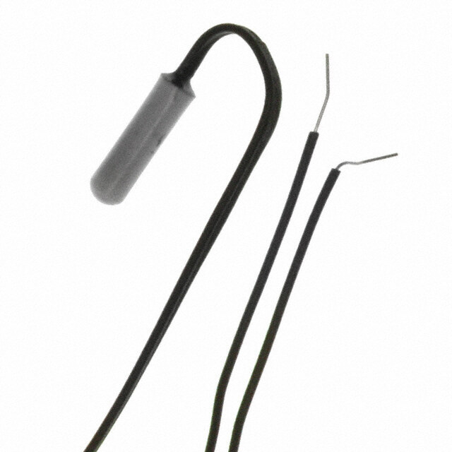
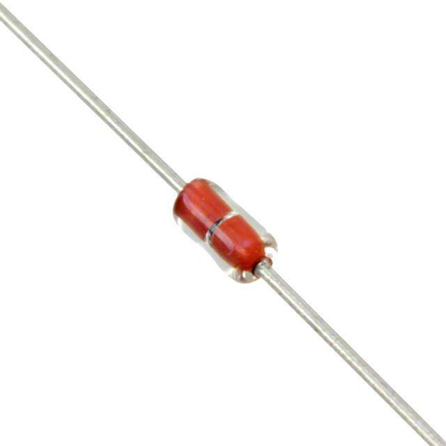
!Note (cid:129) Please read rating and !CAUTION (for storage, operating, rating, soldering, mounting and handling) in this catalog to prevent smoking and/or burning, etc. R44E.pdf (cid:129) This catalog has only typical specifications. Therefore, please approve our product specifications or transact the approval sheet for product specifications before ordering. Mar.6,2020 NTC Thermistors Temperature Sensor Thermo String Cooper Wire Type 1.2±0.4 1.2±0.4 This product is a small flexible lead type NTC Thermistor with a small head and a thin lead wire. Features 1 . pTrhoivsi dsmesa ellx atnredm heiglyh lpyr aecccisuer atetem NpTeCra tTuhreer mseinstsoinrg . 60 to 100±2110 to 150±3 2. The small sensing head and thin lead wire deliver 1 ø0.30±0.05 temperature sensing in a narrow space. 2/- 3+ 3. Flexibility and a wide variety of lengths (60mm to 150mm) The full length 60mm to 150mm interval 10mm. (in mm) enable the design of flexible temperature sensing NXFT15_1B Type (twist) architectures. 4. This product is compatible with our 0402 (EIA) size 1.2±0.4 1.2±0.4 chip Thermistor. 5. Excellent long-term stability 4 6. This is a halogen free product. * * Cl= max.900ppm, Br=max.900ppm and 7 . (N UCXLl+F1BT4r 3s=e4mr, iaFexisl.e 1a N5re0o r0.eEpc1po3mg7n1iz8e8d) .by UL/cUL. 60 to 100±2110 to 150±3 Applications 2/-1 ø0.30±0.05 3+ 1. Temperature compensation for transistors, ICs, and crystal oscillators in mobile communications The full length 60mm to 150mm interval 10mm. (in mm) 2. Temperature sensor for rechargeable batteries NXFT15_2B Type (without twist) 3. Temperature compensation of LCD 4. Temperature compensation in general use of electric circuits Detailed are accessable from the following URL. https://www.murata.com/en-global/products/thermistor/ntc/nxf Resistance B-Constant B-Constant B-Constant B-Constant Maximum Operating Rated Electric Typical Dissipation Thermal Time Part Number (25°C) (25-50°C) (25-80°C) (25-85°C) (25-100°C) Current (25°C) Power (25°C) Constant (25°C) Constant (ohm) (K) (Reference Value) (K) (Reference Value) (K) (Reference Value) (K) (mA) (mW) (mW/°C) (25°C) (s) NXFT15XM202EApBppp 2k±3% 3500±1% 3539 3545 3560 0.27 7.5 1.5 4 NXFT15XV302FApBppp 3k±1% 3936±1% 3971 3977 3989 0.22 7.5 1.5 4 NXFT15XH103FApBppp 10k ±1% 3380 ±1% 3428 3434 3455 0.12 7.5 1.5 4 NXFT15XV103FApBppp 10k ±1% 3936 ±1% 3971 3977 3989 0.12 7.5 1.5 4 NXFT15WB473FApBppp 47k ±1% 4050 ±1% 4101 4108 4131 0.06 7.5 1.5 4 NXFT15WF104FApBppp 100k ±1% 4250 ±1% 4303 4311 4334 0.04 7.5 1.5 4 p is filled with lead shape (1: twist, 2: without twist). ppp is filled with Total-length codes. (60 to 150mm interval 10mm, ex. 060=60mm) Maximum Operating Current rises Thermistor's temperature by 0.1°C Rated Electric Power shows the required electric power that the thermistor's temperature rise to 30°C by self-heating, at ambient temperature of 25 °C. Operating Temperature Range: -40°C to +125°C 23
!Note (cid:129) Please read rating and !CAUTION (for storage, operating, rating, soldering, mounting and handling) in this catalog to prevent smoking and/or burning, etc. R44E.pdf (cid:129) This catalog has only typical specifications. Therefore, please approve our product specifications or transact the approval sheet for product specifications before ordering. Mar.6,2020 NTC Thermistors Temperature Sensor Thermo String Nickel Copper Wire Type 1.2±0.4 1.2±0.4 This product is a small flexible lead type NTC Thermistor with a small head and a thin lead wire. Features 2 0± 0. 1. This small and highly accurate NTC Thermistor 0 to 5 provides extremely precise temperature sensing. 21. Nickel Copper Wire Type has high thermal response than 1 ø0.30±0.05 the Cooper Wire Type. 2/- 3+ 2. The small sensing head and thin lead wire deliver temperature sensing in a narrow space. The full length 21mm, 25 to 50mm interval 5mm. (in mm) 3. Flexibility and a wide variety of lengths (21mm to 50mm) NXFT15_AB Type (without twist) enable the design of flexible temperature sensing architectures. 4. This product is compatible with our 0402 (EIA) size Detailed are accessable from the following URL. chip Thermistor. 4 https://www.murata.com/en-global/products/thermistor/ntc/nxf 5. Excellent long-term stability 6. This is a halogen free product. * * Cl= max.900ppm, Br=max.900ppm and Cl+Br=max.1500ppm 7. NXFT series are recognized by UL/cUL. (UL1434, File No.E137188). Applications 1. Temperature compensation for transistors, ICs, and crystal oscillators in mobile communications 2. Temperature sensor for rechargeable batteries 3. Temperature compensation of LCD 4. Temperature compensation in general use of electric circuits Resistance B-Constant B-Constant B-Constant B-Constant Maximum Operating Rated Electric Typical Dissipation Thermal Time Part Number (25°C) (25-50°C) (25-80°C) (25-85°C) (25-100°C) Current (25°C) Power (25°C) Constant (25°C) Constant (ohm) (K) (Reference Value) (K) (Reference Value) (K) (Reference Value) (K) (mA) (mW) (mW/°C) (25°C) (s) NXFT15XM202EEABppp 2k±3% 3500±1% 3539 3545 3560 0.17 3 0.6 3 NXFT15XV302FEABppp 3k±1% 3936±1% 3971 3977 3989 0.14 3 0.6 3 NXFT15XV502FEABppp 5k±1% 3936±1% 3971 3977 3989 0.11 3 0.6 3 NXFT15XH103FEABppp 10k±1% 3380±1% 3428 3434 3455 0.077 3 0.6 3 NXFT15XV103FEABppp 10k±1% 3936±1% 3971 3977 3989 0.077 3 0.6 3 NXFT15WB473FEABppp 47k±1% 4050±1% 4101 4108 4131 0.036 3 0.6 3 NXFT15WF104FEABppp 100k±1% 4250±1% 4303 4311 4334 0.024 3 0.6 3 ppp is filled with Total-length codes. (21mm, 25 to 50mm interval 5mm, ex. 050=50mm) Maximum Operating Current rises Thermistor's temperature by 0.1°C Rated Electric Power shows the required electric power that the thermistor's temperature rise to 30°C by self-heating, at ambient temperature of 25 °C. Operating Temperature Range: -40°C to +125°C 24
!Note (cid:129) Please read rating and !CAUTION (for storage, operating, rating, soldering, mounting and handling) in this catalog to prevent smoking and/or burning, etc. R44E.pdf (cid:129) This catalog has only typical specifications. Therefore, please approve our product specifications or transact the approval sheet for product specifications before ordering. Mar.6,2020 Temperature Sensor Thermo String Type Specifications and Test Methods No. Item Specifications Test Methods Except XM202&XV302 XM202&XV302 High Temperature · Resistance (R25°C) 1 Storage Test fluctuation rate: less than ±3%. 125±2°C in air, for 1000 +48/-0hrs. without loading. · Resistance (R25°C) · B-Constant (B25/50°C) fluctuation rate: less than ±1%. fluctuation rate: less than ±2%. · B-Constant (B25/50°C) · Resistance (R25°C) Low Temperature fluctuation rate: less than ±1%. fluctuation rate: less than ±1%. 2 -40 +0/-3°C in air, for 1000 +48/-0hrs. without loading. Storage Test · B-Constant (B25/50°C) fluctuation rate: less than ±1%. · Resistance (R25°C) Humidity fluctuation rate: less than ±2%. 60±2°C, 90 to 95%RH in air, for 1000 +48/-0hrs. without 3 Storage Test · B-Constant (B25/50°C) loading. fluctuation rate: less than ±1%. -40 +0/-3°C, 30min. in air · Resistance (R25°C) · Resistance (R25°C) +25±2°C, 10 to 15min. in air Temperature fluctuation rate: less than ±2%. fluctuation rate: less than ±3%. 4 +125±2°C, 30min. in air Cycle · B-Constant (B25/50°C) · B-Constant (B25/50°C) +25 +2/-0°C, 10 to 15min. in air (1 cycle) fluctuation rate: less than ±1%. fluctuation rate: less than ±2%. Continuous 100 cycles, without loading. · Resistance (R25°C) High Temperature fluctuation rate: less than ±3%. 85±2°C in air, with 'Operating Current for Sensor' for 1000 5 Load · B-Constant (B25/50°C) +48/-0hrs. fluctuation rate: less than ±2%. 4 2mm length of coating resin from the top of Thermistor is to be Insulation Break - 6 · No damage electrical characteristics at DC100 V, 1min. dipped into beads of lead (Pb), and DC100V 1min. is applied to down Voltage circuit between beads of lead (Pb) and lead wire. Both lead wires are dipped into 350±10°C solder for 3.5±0.5sec., or 260±5°C solder for 10±1sec. according to Fig-1 (solder <JIS Z 3282 SnAgCu>). Resistance to · Resistance (R25°C) fluctuation rate: less than ±1%. 7 Soldering Heat · B-Constant (B25/50°C) fluctuation rate: less than ±1%. 1 to 2mm Solder Fig-1 Both lead wires are dipped into flux (25wt% colophony <JIS K 5902> isopropyl alcohol <JIS K 8839>) for 5 to 10sec. Then 8 Solderability More than 90% of lead wire surface shall be covered by solder. both lead wires are dipped into 245±5°C solder <JIS Z 3282 SnAgCu> for 2±0.5sec. according to Fig-1. The lead wire shall be inserted in a ø1.0mm hole until resin part contacts with a substrate as shown in Fig.-2, and 1N force for 10sec. shall be applied to the lead wire. Lead Wire · Resistance (R25°C) fluctuation rate: less than ±1%. 9 Pull Strength · B-Constant (B25/50°C) fluctuation rate: less than ±1%. 1N (10sec.) Fig-2 * · R25 is zero-power resistance at 25°C. · B25/50 is calculated by zero-power resistance of Thermistor in 25°C-50°C. · After each test, NTC Thermistor should be kept for 1hr. at room temperature (normal humidity and normal atmospheric pressure). Continued on the following page. 25
!Note (cid:129) Please read rating and !CAUTION (for storage, operating, rating, soldering, mounting and handling) in this catalog to prevent smoking and/or burning, etc. R44E.pdf (cid:129) This catalog has only typical specifications. Therefore, please approve our product specifications or transact the approval sheet for product specifications before ordering. Mar.6,2020 Temperature Sensor Thermo String Type Specifications and Test Methods Continued from the preceding page. No. Item Specifications Test Methods Hold the lead wires as in Fig-3. Bend by 90 degrees and again bend back to the initial position. Then bend to the other side by 90 degrees and again bend back to the initial position. After bending process, 10N force for 3sec. shall be applied to the lead wire. Lead Wire 10 · Lead wire does not break. Bending Strength 10N (3 sec.) Fig-3 NTC Thermistor shall be dropped without any force onto 11 Free Fall concrete floor from 1 meter height one time. NTC Thermistor shall be fixed to the vibration test equipment. Vibration of total 1.5 mm amplitude, Frequency sequence of 10Hz - 55Hz - 10Hz in 1min. shall be applied for right angled 3 directions for 2hrs. duration each. 4 · Resistance (R25°C) fluctuation rate: less than ±1%. · B-Constant (B25/50°C) fluctuation rate: less than ±1%. 12 Vibration · No visible damage at resin part. Mount Oscillating Direction Z Solder is attached from the reverse side. Oscillating Direction Y Oscillating Direction X * · R25 is zero-power resistance at 25°C. · B25/50 is calculated by zero-power resistance of Thermistor in 25°C-50°C. · After each test, NTC Thermistor should be kept for 1hr. at room temperature (normal humidity and normal atmospheric pressure). 26
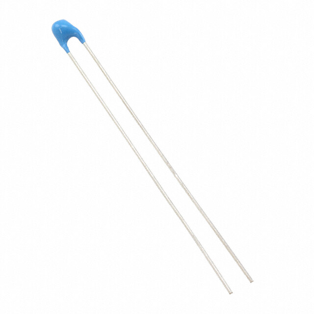
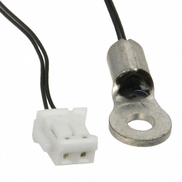
!Note (cid:129) Please read rating and !CAUTION (for storage, operating, rating, soldering, mounting and handling) in this catalog to prevent smoking and/or burning, etc. R44E.pdf (cid:129) This catalog has only typical specifications. Therefore, please approve our product specifications or transact the approval sheet for product specifications before ordering. Mar.6,2020 NTC Thermistors Temperature Sensor Lead Type 4.0 max. 2.0 max. This thermistor is for normal temperature level sensors having self-subsistence due to strong lead strength based on chip NTC. 1 0 .0 Features to 5 0 .0 1. This highly accurate NTC Thermistor provides extremely 2.5±1 ±1.0 precise temperature sensing. 2. This product is compatible with 1005 (1.0mm x 0.5mm) ø0.40±0.05 size NTC Thermistor. 3. The variation per hour of this product is highly stable. The full length 10.0 to 50.0mm interval 10.0mm (in mm) 4. This product is produced with an automation line that was consistent from lead to packaging so that a product of uniform quality may be obtained at low cost in large Detailed are accessable from the following URL. quantities. https://www.murata.com/en-global/products/thermistor/ntc/nxr 5. Since this product has strong lead intensity with original lead mounting technique, it is bent at the time of use and can withstand processing, etc., readily. Taping package can be supported. Applications 1. For temperature detection of a rechargeable battery pack 5 2. For temperature detection of a charge circuit 3. For temperature detection of a printer head 4. For temperature detection of a DC fan motor 5. For temperature detection of home electronics Resistance B-Constant B-Constant B-Constant B-Constant Maximum Operating Rated Electric Typical Dissipation Thermal Time Part Number (25°C) (25-50°C) (25-80°C) (25-85°C) (25-100°C) Current (25°C) Power (25°C) Constant (25°C) Constant (ohm) (K) (Reference Value) (K) (Reference Value) (K) (Reference Value) (K) (mA) (mW) (mW/°C) (25°C) (s) NXRT15XM202EA1Bppp 2k ±3% 3500 ±1% 3539 3545 3560 0.27 7.5 1.5 4 NXRT15XV302FA1Bppp 3k ±1% 3936 ±1% 3971 3977 3989 0.22 7.5 1.5 4 NXRT15XV502FA1Bppp 5k ±1% 3936 ±1% 3971 3977 3989 0.17 7.5 1.5 4 NXRT15XH103FA1Bppp 10k ±1% 3380 ±1% 3428 3434 3455 0.12 7.5 1.5 4 NXRT15XV103FA1Bppp 10k ±1% 3936 ±1% 3971 3977 3989 0.12 7.5 1.5 4 NXRT15WB333JA1Bppp 33k ±5% 4050 ±3% 4101 4108 4131 0.07 7.5 1.5 4 NXRT15WB473FA1Bppp 47k ±1% 4050 ±1% 4101 4108 4131 0.06 7.5 1.5 4 NXRT15WF104FA1Bppp 100k ±1% 4250 ±1% 4303 4311 4334 0.04 7.5 1.5 4 ppp is filled with Total-length codes. (10 to 50mm interval 10mm, ex. 040=40mm) Maximum Operating Current rises Thermistor's temperature by 0.1°C. Rated Electric Power is necessary electric power that thermistor's temperature rises 5°C by self-heating at 25°C in still air. Taping type of part numbers with "3A016" is available (Lead Spacing=5mm). Operating Temperature Range: -40°C to +125°C 27
!Note (cid:129) Please read rating and !CAUTION (for storage, operating, rating, soldering, mounting and handling) in this catalog to prevent smoking and/or burning, etc. R44E.pdf (cid:129) This catalog has only typical specifications. Therefore, please approve our product specifications or transact the approval sheet for product specifications before ordering. Mar.6,2020 Temperature Sensor Lead Type Specifications and Test Methods No. Item Specifications Test Methods Low Temperature 1 -40 +0/-3°C in air, for 1000 +48/-0hrs. without loading. Storage Test · Resistance (R25°C) fluctuation rate: less than ±1%. High Temperature · B-Constant (B25/50°C) fluctuation rate: less than ±1%. 2 125±2°C in air, for 1000 +48/-0hrs. without loading. Storage Test High Temperature 85±2°C in air, with ‘Operating Current for Sensor’ for 3 Load 1000 +48/-0hrs. Humidity Storage 60±2°C, 90 to 95%RH in air, for 1000 +48/-0hrs. without 4 Test loading. · Resistance (R25°C) fluctuation rate: less than ±2%. · B-Constant (B25/50°C) fluctuation rate: less than ±1%. -40°C +0/-3°C, 30min. in air +25°C±2°C, 10 to 15min. in air Temperature 5 +125°C +3/-0°C, 30min. in air Cycle +25°C +2/-0°C, 10 to 15min. in air (1 cycle) Continuous 100 cycles, without loading. 2mm length of coating resin from the top of thermistor is to be Insulation Break - 6 · No damage electrical characteristics on D.C.100 V, 1min. dipped into beads of lead (Pb), and DC100V 1min. is applied to down Voltage circuit between beads of lead (Pb) and lead wire. Both lead wires are dipped into 350±10°C solder for 3.5±0.5sec., or 260±5°C solder for 10±1sec. according to Fig-1. (solder <Sn-3Ag-0.5Cu>) Resistance to · Resistance (R25°C) fluctuation rate: less than ±1%. 7 Soldering Heat · B-Constant (B25/50°C) fluctuation rate: less than ±1%. Solder Fig-1 Both lead wires are dipped into flux (25wt% colophony 5 · More than 90% of lead wire surface shall be covered by <JIS K 5902> isopropyl alcohol <JIS K 8839>) for 5 to 10 sec. 8 Solderability solder. Then both lead wires are dipped into 245±5°C solder <Sn-3Ag-0.5Cu> for 2±0.5sec. according to Fig-1. One end of a lead wire shall be fixed and 2.5N force for 10sec. shall be applied to the other lead wire as shown in Fig-2. · Resistance(R25°C) fluctuation rate: less than ±1%. Lead Wire Pull 9 · B-Constant(B25/50°C) fluctuation rate: less than ±1%. Strength · No visible damage at resin part. 2.5N (10sec.) Fig-2 One lead wire is held and 2.5N force is applied. Then the body of NTC thermistor is bent by 90° and again bent back to the initial position. This sequence shall be completed twice. See Fig-3. Lead Wire Bending 10 · Lead wire does not break. Strength 90° 2.5N Fig-3 NTC thermistor shall be dropped without any force onto 11 Free Fall concrete floor from 1 meter height one time. · Resistance (R25°C) fluctuation rate: less than ±1%. · B-Constant (B25/50°C) fluctuation rate: less than ±1%. NTC thermistor shall be fixed to the vibration test Equipment. 12 Vibration · No visible damage at resin part. Vibration of total 1.5mm amplitude, Frequency sequence of 10Hz – 55Hz – 10Hz in 1min., shall be applied for right angled 3 directions for 2hrs. duration each. * · R25 is zero-power resistance at 25°C. · B25/50 is calculated by zero-power resistance of Thermistor in 25°C-50°C. · After each test, NTC Thermistor should be kept for 1hr. at room temperature (normal humidity and normal atmospheric pressure). 28
!Note (cid:129) Please read rating and !CAUTION (for storage, operating, rating, soldering, mounting and handling) in this catalog to prevent smoking and/or burning, etc. R44E.pdf (cid:129) This catalog has only typical specifications. Therefore, please approve our product specifications or transact the approval sheet for product specifications before ordering. Mar.6,2020 NTC Thermistors Temperature Sensor Lead Insulation Type 4.0 max. 2.0 max. This thermistor is for normal temperature level sensors having self-subsistence due to strong lead strength mm) 0 based on chip NTC. (5. A 0 1. Features 2.5±1.0 0.0± 5 B 0 to 1. NXR series can accurately detect temperature with 25. NCP15 series on the head of parts. 0.46±0.05 2. The insulation coat with polyulethane on the surface of lead wire : 100VDC. The full length 25.0 to 50.0mm interval 5.0mm 3. You can choose NTC characteristics from NCP15 series. A: Epoxy Resin B: Copper Lead Wire with Polyurethane Coat (in mm) 4. The resistance drift is low in the reliability test. 5. The production capacity is bigger and NXR is produced almost entirely in an automation line. Detailed are accessable from the following URL. 6. Adopt to Sb regulation https://www.murata.com/en-global/products/thermistor/ntc/nxr Applications 1. Secondary battery 2. Temperature detection for charging 3. Temperature detection for DC fan motor 4. Temperature sensing for appliance 5. Self-standing temperature sensing for fire detector Resistance B-Constant B-Constant B-Constant B-Constant Maximum Operating Rated Electric Typical Dissipation Thermal Time Part Number (25°C) (25-50°C) (25-80°C) (25-85°C) (25-100°C) Current (25°C) Power (25°C) Constant (25°C) Constant (ohm) (K) (Reference Value) (K) (Reference Value) (K) (Reference Value) (K) (mA) (mW) (mW/°C) (25°C) (s) NXRT15XM202EA5Bppp 2k ±3% 3500 ±1% 3539 3545 3560 0.36 13 2.6 4 NXRT15XV302FA5Bppp 3k ±1% 3936 ±1% 3971 3977 3989 0.29 13 2.6 4 NXRT15XV502FA5Bppp 5k ±1% 3936 ±1% 3971 3977 3989 0.23 13 2.6 4 NXRT15XH103FA5Bppp 10k ±1% 3380 ±1% 3428 3434 3455 0.16 13 2.6 4 6 NXRT15XV103FA5Bppp 10k ±1% 3936 ±1% 3971 3977 3989 0.16 13 2.6 4 NXRT15WB333JA5Bppp 33k ±5% 4050 ±3% 4101 4108 4131 0.08 13 2.6 4 NXRT15WB473FA5Bppp 47k ±1% 4050 ±1% 4101 4108 4131 0.07 13 2.6 4 NXRT15WF104FA5Bppp 100k ±1% 4250 ±1% 4303 4311 4334 0.05 13 2.6 4 ppp is fulled with Total-length codes. (25 to 50mm interval 5mm, ex. 030=30mm) Maximum Operating Current rises Thermistor's temperature by 0.1°C. Rated Electric Power is necessary electric power that thermistor's temperature rises 5°C by self-heating at 25°C in still air. Operating Temperature Range: -40°C to +125°C 29
!Note (cid:129) Please read rating and !CAUTION (for storage, operating, rating, soldering, mounting and handling) in this catalog to prevent smoking and/or burning, etc. R44E.pdf (cid:129) This catalog has only typical specifications. Therefore, please approve our product specifications or transact the approval sheet for product specifications before ordering. Mar.6,2020 Temperature Sensor Lead Insulation Type Specifications and Test Methods No. Item Specifications Test Methods Both lead wires are dipped into 350±10°C solder for 3.5±0.5sec., or 260 ±5°C solder for 10±1sec. according to Fig-1. (solder <SnAgCu>) Resistance to · Resistance (R25°C) fluctuation rate: less than ±1%. 1 Soldering Heat · B-Constant (B25/50°C) fluctuation rate: less than ±1%. (Flow) Solder 1 to 2mm Fig-1 Both lead wires are dipped into flux (25wt% colophony Solderability · More than 90% of lead wsire surface shall be covered by <JIS K 5902> isopropyl alcohol <JIS K 8839>) for 5 to 10sec. 2 (Flow) solder. Then both lead wire are dipped into 245±5°C solder <SnAgCu> for 2±0.5sec. according to Fig-1. One end of a lead wire shall be fixed and 2.5N force for 10sec. shall be applied to the other lead wire as shown in Fig-2. Lead Wire · Resistance (R25°C) fluctuation rate: less than ±1%. 3 Breaking Strength · B-Constant (B25/50°C) fluctuation rate: less than ±1%. 2.5N (10sec.) Fig-2 One lead wire is held and 2.5N force is applied. Then the body of NTC thermistor is bent by 90° and again bent back to the initial position. This sequence shall be completed twice. See Fig-3. Lead Wire Bending 4 · Lead wire does not break. Strength 90° 6 2.5N Fig-3 NTC thermistor shall be dropped without any force onto 5 Free Fall concrete floor from 1 meter height one time. · Resistance (R25°C) fluctuation rate: less than ±1%. · B-Constant (B25/50°C) fluctuation rate: less than ±1%. NTC thermistor shall be fixed to the vibration test equipment. 6 Vibration · No visible damage at resin part. Vibration of total 1.5 mm amplitude, frequency sequence of 10Hz - 55Hz - 10Hz in 1min., shall be applied for right angled 3 directions for 2hrs. duration each. 7 Cold · Resistance (R25°C) fluctuation rate: less than ±1%. -40 +0/-3°C in air, for 1000 +48/-0hrs. without loading. 8 Dry Heat · B-Constant (B25/50°C) fluctuation rate: less than ±1%. 125±2°C in air, for 1000 +48/-0hrs. without loading. High Temperature 85±2°C in air, with ‘Operating Current for Sensor’ 9 with Continuous for 1000 +48/-0hrs. Load 60±2°C, 90 to 95%RH in air, for 1000 +48/-0hrs. without 10 Damp Heat · Resistance (R25°C) fluctuation rate: less than ±2%. loading. · B-Constant (B25/50°C) fluctuation rate: less than ±1%. -40°C +0/-3°C, 30min. in air +25°C±2°C, 10 to 15min. in air Change of 11 +125°C +3/-0°C, 30min. in air Temperature +25°C +2/-0°C, 10 to 15min. in air (1 cycle) Continuous 100 +4/-0 cycles, without loading. Dielectric 2mm length of coating resin from the top of thermistor is to be 12 Breakdown · No damage electrical characteristics on D.C.100V, 1min. dipped into beads of lead (Pb), and DC100V 1min. is applied to Voltage circuit between beads of lead (Pb) and lead wire. 30
!Note (cid:129) Please read rating and !CAUTION (for storage, operating, rating, soldering, mounting and handling) in this catalog to prevent smoking and/or burning, etc. R44E.pdf (cid:129) This catalog has only typical specifications. Therefore, please approve our product specifications or transact the approval sheet for product specifications before ordering. Mar.6,2020 Temperature Sensor Thermo String/Lead Type Temperature Characteristics (Center Value) Part Number NXFT15XM202 NXFT15XV302 NXFT15XV502 NXFT15XH103 NXFT15XV103 NXFT15WB473 NXFT15WF104 Resistance 2kΩ 3kΩ 5kΩ 10kΩ 10kΩ 47kΩ 100kΩ B-Constant 3500K 3936K 3936K 3380K 3936K 4050K 4250K Temp. (°C) Resistance (kΩ) Resistance (kΩ) Resistance (kΩ) Resistance (kΩ) Resistance (kΩ) Resistance (kΩ) Resistance (kΩ) –40 44.981 101.251 168.752 195.652 337.503 1747.920 4397.119 –35 33.671 73.000 121.666 148.171 243.332 1245.428 3088.599 –30 25.444 53.249 88.748 113.347 177.496 898.485 2197.225 –25 19.417 39.258 65.430 87.559 130.859 655.802 1581.881 –20 14.955 29.228 48.714 68.237 97.428 483.954 1151.037 –15 11.619 21.969 36.615 53.650 73.230 360.850 846.579 –10 9.097 16.659 27.764 42.506 55.529 271.697 628.988 –5 7.178 12.740 21.233 33.892 42.467 206.463 471.632 0 5.707 9.824 16.374 27.219 32.747 158.214 357.012 5 4.568 7.635 12.725 22.021 25.450 122.259 272.500 10 3.682 5.980 9.966 17.926 19.932 95.227 209.710 15 2.986 4.718 7.864 14.674 15.727 74.730 162.651 20 2.437 3.749 6.249 12.081 12.498 59.065 127.080 25 2.000 3.000 5.000 10.000 10.000 47.000 100.000 30 1.651 2.416 4.027 8.315 8.054 37.643 79.222 35 1.370 1.959 3.264 6.948 6.529 30.334 63.167 40 1.143 1.597 2.662 5.834 5.324 24.591 50.677 45 0.958 1.310 2.183 4.917 4.366 20.048 40.904 50 0.807 1.080 1.801 4.161 3.601 16.433 33.195 55 0.682 0.896 1.493 3.535 2.985 13.539 27.091 60 0.580 0.746 1.244 3.014 2.488 11.209 22.224 65 0.495 0.625 1.041 2.586 2.083 9.328 18.323 70 0.424 0.526 0.876 2.228 1.752 7.798 15.184 75 0.365 0.444 0.740 1.925 1.480 6.544 12.635 80 0.315 0.377 0.628 1.669 1.256 5.518 10.566 85 0.273 0.321 0.535 1.452 1.070 4.674 8.873 90 0.237 0.275 0.458 1.268 0.916 3.972 7.481 95 0.207 0.236 0.394 1.110 0.787 3.388 6.337 100 0.181 0.204 0.340 0.974 0.679 2.902 5.384 105 0.160 0.177 0.294 0.858 0.588 2.494 4.594 110 0.141 0.154 0.256 0.758 0.512 2.150 3.934 115 0.124 0.134 0.223 0.672 0.446 1.860 3.380 120 0.110 0.117 0.195 0.596 0.391 1.615 2.916 125 0.098 0.103 0.172 0.531 0.343 1.406 2.522 Part Number NXRT15XM202 NXRT15XV302 NXRT15XV502 NXRT15XH103 NXRT15XV103 NXRT15WB333 NXRT15WB473 NXRT15WF104 Resistance 2.0kΩ 3.0kΩ 5.0kΩ 10kΩ 10kΩ 33kΩ 47kΩ 100kΩ B-Constant 3500K 3936K 3936K 3380K 3936K 4050K 4050K 4250K Temp. (°C) Resistance (kΩ) Resistance (kΩ) Resistance (kΩ) Resistance (kΩ) Resistance (kΩ) Resistance (kΩ) Resistance (kΩ) Resistance (kΩ) –40 44.981 101.251 168.752 195.652 337.503 1227.263 1747.920 4397.119 –35 33.671 73.000 121.666 148.171 243.332 874.449 1245.428 3088.599 –30 25.444 53.249 88.748 113.347 177.496 630.851 898.485 2197.225 –25 19.417 39.258 65.430 87.559 130.859 460.457 655.802 1581.881 –20 14.955 29.228 48.714 68.237 97.428 339.797 483.954 1151.037 –15 11.619 21.969 36.615 53.650 73.230 253.363 360.850 846.579 –10 9.097 16.659 27.764 42.506 55.529 190.766 271.697 628.988 –5 7.178 12.740 21.233 33.892 42.467 144.964 206.463 471.632 0 5.707 9.824 16.374 27.219 32.747 111.087 158.214 357.012 5 4.568 7.635 12.725 22.021 25.450 85.842 122.259 272.500 10 3.682 5.980 9.966 17.926 19.932 66.861 95.227 209.710 15 2.986 4.718 7.864 14.674 15.727 52.470 74.730 162.651 20 2.437 3.749 6.249 12.081 12.498 41.471 59.065 127.080 25 2.000 3.000 5.000 10.000 10.000 33.000 47.000 100.000 30 1.651 2.416 4.027 8.315 8.054 26.430 37.643 79.222 35 1.370 1.959 3.264 6.948 6.529 21.298 30.334 63.167 40 1.143 1.597 2.662 5.834 5.324 17.266 24.591 50.677 45 0.958 1.310 2.183 4.917 4.366 14.076 20.048 40.904 50 0.807 1.080 1.801 4.161 3.601 11.538 16.433 33.195 55 0.682 0.896 1.493 3.535 2.985 9.506 13.539 27.091 60 0.580 0.746 1.244 3.014 2.488 7.870 11.209 22.224 65 0.495 0.625 1.041 2.586 2.083 6.549 9.328 18.323 70 0.424 0.526 0.876 2.228 1.752 5.475 7.798 15.184 75 0.365 0.444 0.740 1.925 1.480 4.595 6.544 12.635 80 0.315 0.377 0.628 1.669 1.256 3.874 5.518 10.566 85 0.273 0.321 0.535 1.452 1.070 3.282 4.674 8.873 90 0.237 0.275 0.458 1.268 0.916 2.789 3.972 7.481 95 0.207 0.236 0.394 1.110 0.787 2.379 3.388 6.337 100 0.181 0.204 0.340 0.974 0.679 2.038 2.902 5.384 105 0.160 0.177 0.294 0.858 0.588 1.751 2.494 4.594 110 0.141 0.154 0.256 0.758 0.512 1.509 2.150 3.934 115 0.124 0.134 0.223 0.672 0.446 1.306 1.860 3.380 120 0.110 0.117 0.195 0.596 0.391 1.134 1.615 2.916 125 0.098 0.103 0.172 0.531 0.343 0.987 1.406 2.522 31
!Note (cid:129) Please read rating and !CAUTION (for storage, operating, rating, soldering, mounting and handling) in this catalog to prevent smoking and/or burning, etc. R44E.pdf (cid:129) This catalog has only typical specifications. Therefore, please approve our product specifications or transact the approval sheet for product specifications before ordering. Mar.6,2020 Temperature Sensor Thermo String/Lead Type !Caution/Notice !Caution (Storage and Operating Conditions) This product is designed for application in an 2. Volatile or flammable gas ordinary environment (normal room temperature, 3. Dusty conditions humidity and atmospheric pressure). 4. Under vacuum, or under high or low pressure Do not use under the following conditions because 5. Wet or humid locations all of these factors can deteriorate the product 6. Places with salt water, oils, chemical liquids or characteristics or cause failures and burn-out. organic solvents 1. Corrosive gas or deoxidizing gas 7. Strong vibrations (Chlorine gas, Hydrogen sulfide gas, Ammonia gas, 8. Other places where similar hazardous conditions Sulfuric acid gas, Nitric oxide gas, etc.) exist !Caution (Others) Be sure to provide an appropriate fail-safe function on your product to prevent secondary damage that may be caused by the abnormal function or the failure of our product. Notice (Storage and Operating Conditions) To keep the solderability of the product from degrading, 3. Handling after unpacking: the following storage condition is recommended. After unpacking, reseal product promptly or 1. Storage condition: store it in a sealed container with a drying agent. Temperature -10 to +40°C 4. Storage place: Humidity less than 75%RH (not dewing condition) Do not store this product in corrosive gas 2. Storage term: (Sulfuric acid gas, Chlorine gas, etc.) or in direct Use this product within 6 months after delivery by sunlight. first-in and first-out stocking system. Notice (Rating) Use this product within the specified temperature range. Higher temperature may cause deterioration of the characteristics or the material quality of this product. Notice (Soldering and Mounting) NXF Series Please note as shown below when you mount this product. 2. Do not touch the resin head directly with the soldering 1. Do not melt the solder in the resin head when you solder iron. It may cause the melting of solder in the resin head. this product. If you do so, there is a possibility of wire 3. Do not separate the parallel lead wires 10mm or less breakage, electric short mode failure and wire coating from the resin. breakage. If you cut the lead wire of this product less 4. If you mold this product with resin, please evaluate than 20mm from the resin head, the heat of the melted the quality of this product before you use it. solder at the lead wire edge is propagated easily to the 5. Do not bend the lead wire radius 1mm or more. resin head along the lead wire. Continued on the following page. 32
!Note (cid:129) Please read rating and !CAUTION (for storage, operating, rating, soldering, mounting and handling) in this catalog to prevent smoking and/or burning, etc. R44E.pdf (cid:129) This catalog has only typical specifications. Therefore, please approve our product specifications or transact the approval sheet for product specifications before ordering. Mar.6,2020 Temperature Sensor Thermo String/Lead Type !Caution/Notice Continued from the preceding page. Notice (Soldering and Mounting) NXR Series Please note as shown below when you mount this product. 2. Do not touch the resin head directly with the solder iron. 1. Do not melt the solder in the resin head, when you solder It may cause the melting of solder in the resin head. this product. If you melt the solder in resin the head, 3. If you mold this product with resin, please evaluate the wire could break and short. the quality of this product before you use it. If you cut the lead wire of this product less than 8mm from the resin head, the heat of the melted solder at the lead wire edge is propagated easily to the resin head along the lead wire. Please do not cut this product below 9mm. Notice (Soldering and Mounting) NXR Series (Insulation Type) Please note as shown below when you mount this product. Please talk to us if you have concern matter, like 1. Do not melt the solder in the resin head when you solder process it under the high temperature and the high this product. (more than 25mm in full length of the pressure. product). (For example, exposed to high-temperature and If you melt the solder in the resin head, it has posibility high-pressure environment as mold sealing with that the wire could break and short. injection molding.) 2. Do not touch the resin head directly with the solder iron. It may cause the melting of solder in the resin head. 3. When additonal processing is carried out on this product (such as bonding, resin molding, and resin coating, etc.), please perform an audit of quality level on an automated machine and only use the product after confirming its reliability. Notice (Handling) NXF/NXR Series 1. The ceramic element of this product is fragile, and care must be taken not to load an excessive press-force or not to cause a shock at handling. Such forces may cause cracking or chipping. 2. Do not apply excessive force to the lead. Otherwise, it may cause the junction between lead and element to break or crack. Holding the element by the side lead wire is recommended when lead wire is bent or cut. Notice (Handling) NXR Series (Insulation Type) 1. The ceramic element of this product is fragile, and 2. Do not apply excessive force to the lead. care must be taken not to load an excessive Otherwise, it may cause the junction between lead and press-force or not to cause a shock at handling. element to break or crack. Such forces may cause cracking or chipping. Holding the element by the side lead wire is recommended Especially under high-temperature environment, when lead wire is bent or cut. there is a possibility that epoxy resin will become soft. Handle the lead with care; there is a possibility When you set up the processing environment, please that a crack may go into the polyurethane examine the processing method after evaluating the insulated coat when bending the lead. quality of this product. 33
!Note (cid:129) Please read rating and !CAUTION (for storage, operating, rating, soldering, mounting and handling) in this catalog to prevent smoking and/or burning, etc. R44E.pdf (cid:129) This catalog has only typical specifications. Therefore, please approve our product specifications or transact the approval sheet for product specifications before ordering. Mar.6,2020 Temperature Sensor Thermo String/Lead Type Package Minimum Order Quantity Bulk Ammo Pack Taping Part Number Minimum Quantity (pcs.) Part Number Minimum Quantity (pcs.) NXF 1,000 - - NXR 500 NXRT_3A016 2,500 Taping Dimensions (NXRT_3A016 Series) Δh1 Δh2 P2 P ΔS T D H3 F P1 ød W2 H0 L3 W1 W0 W3 I øD0 P0 t2 t1 Item Code Dimensions (mm) Pitch of Component P 12.7±1.0 Pitch of Sprocket Hole P0 12.7±0.3 Lead Spacing F 5.0±1.0 Length from Hole Center to Component Center P2 6.35±1.3 Length from Hole Center to Lead P1 3.85±0.7 Body Diameter D 4.0 max. Deviation Along Tape, Left or Right ΔS 0±2.0 Carrier Tape Width W3 18.0±0.5 Position of Sprocket Hole W1 9.0±0.5 Lead Distance between Reference and Bottom Planes H0 16.0±1.0 Height of Component H3 7.5±1.0 Protrusion Length I +0.5 to −1.0 Diameter of Sprocket Hole øD0 4.0±0.1 Lead Diameter ød 0.40±0.05 Total Tape Thickness t1 0.6±0.3 Total Thickness, Tape and Lead Wire t2 1.6 max. Deviation Across Tape Δh1, Δh2 1.0 max. Portion to Cut in Case of Defect L3 11.0 +– 02 . 0 Hold down Tape Width W0 9.5 min. Hold down Tape Position W2 1.5±1.5 Thickness T 2.0 max. 34
R44E.pdf Mar.6,2020 Cat. No. R44E-19 Global Locations For details please visit www.murata.com Note 1 Export Control 2 Please contact our sales representatives or 3 Product specifi cations in this catalog are as of product engineers before using the products in February 2020. They are subject to change or For customers outside Japan: this catalog for the applications listed below, our products in it may be discontinued without No Murata products should be used or which require especially high reliability for the advance notice. Please check with our sales sold, through any channels, for use in the prevention of defects which might directly representatives or product engineers before design, development, production, utilization, damage a third party’s life, body or property, or ordering. If there are any questions, please contact maintenance or operation of, or otherwise when one of our products is intended for use our sales representatives or product engineers. contribution to (1) any weapons (Weapons of in applications other than those specified in Mass Destruction [nuclear, chemical or biological this catalog. 4 Please read rating and CAUTION (for storage, weapons or missiles] or conventional weapons) operating, rating, soldering, mounting and or (2) goods or systems specially designed or 1 Aircraft equipment handling) in this catalog to prevent smoking intended for military end-use or utilization by 2 Aerospace equipment and/or burning, etc. military end-users. 3 Undersea equipment 5 This catalog has only typical specifi cations. For customers in Japan: Therefore, please approve our product 4 Power plant equipment specifi cations or transact the approval sheet For products which are controlled items subject for product specifi cations before ordering. to the “Foreign Exchange and Foreign Trade Law” 5 Medical equipment of Japan, the export license specifi ed by the law 6 Please note that unless otherwise specifi ed, we is required for export. 6 Transportation equipment (vehicles, trains, shall assume no responsibility whatsoever for any ships, etc.) confl ict or dispute that may occur in connection 7 Traffi c signal equipment with the eff ect of our and/or a third party’s intellectual property rights and other related 8 Disaster prevention / crime prevention rights in consideration of your use of our products equipment and/or information described or contained in our catalogs. In this connection, no representation 9 Data-processing equipment shall be made to the eff ect that any third parties are authorized to use the rights mentioned above 10 Application of similar complexity and/or under licenses without our consent. reliability requirements to the applications listed above 7 No ozone depleting substances (ODS) under the Montreal Protocol are used in our manufacturing process. Murata Manufacturing Co., Ltd. www.murata.com