ICGOO在线商城 > MS3122E22-55PX

 Datasheet下载
- 型号: MS3122E22-55PX
- 制造商: Amphenol
- 库位|库存: xxxx|xxxx
- 要求:
| 数量阶梯 | 香港交货 | 国内含税 |
| +xxxx | $xxxx | ¥xxxx |
查看当月历史价格
查看今年历史价格
MS3122E22-55PX产品简介:
ICGOO电子元器件商城为您提供MS3122E22-55PX由Amphenol设计生产,在icgoo商城现货销售,并且可以通过原厂、代理商等渠道进行代购。 提供MS3122E22-55PX价格参考¥452.06-¥753.43以及AmphenolMS3122E22-55PX封装/规格参数等产品信息。 你可以下载MS3122E22-55PX参考资料、Datasheet数据手册功能说明书, 资料中有MS3122E22-55PX详细功能的应用电路图电压和使用方法及教程。
| 参数 | 数值 |
| 产品目录 | |
| 描述 | CONN RCPT 55POS BOX MNT W/PINS |
| 产品分类 | |
| 品牌 | Amphenol Industrial Operations |
| 数据手册 | |
| 产品图片 | |
| 产品型号 | MS3122E22-55PX |
| rohs | 含铅 / 不符合限制有害物质指令(RoHS)规范要求 |
| 产品系列 | 军用,MIL-DTL-26482 系列 I,PT |
| 产品培训模块 | http://www.digikey.cn/PTM/IndividualPTM.page?site=cn&lang=zhs&ptm=25050http://www.digikey.cn/PTM/IndividualPTM.page?site=cn&lang=zhs&ptm=25182 |
| 侵入防护 | 抗环境影响 |
| 其它名称 | MS3122E22-55PX-ND |
| 包装 | 散装 |
| 外壳尺寸-插件 | 22-55 |
| 外壳尺寸,MIL | - |
| 外壳材料,镀层 | 铝,镀草绿色镉 |
| 安装类型 | 面板安装,法兰 |
| 工作温度 | -55°C ~ 125°C |
| 朝向 | X |
| 标准包装 | 1 |
| 特性 | - |
| 电压-额定 | 600VAC |
| 端接 | 压接 |
| 紧固类型 | 插销锁 |
| 触头镀层 | 金 |
| 触头镀层厚度 | - |
| 连接器类型 | 插座,公形引脚 |
| 配套产品 | /product-detail/zh/MS3126F22-55SX/AMS3126F22-55SX-ND/2131473/product-detail/zh/MS3126E22-55SX/AMS3126E22-55SX-ND/2131314/product-detail/zh/MS3116F22-55SX/AMS3116F22-55SX-ND/2130546/product-detail/zh/MS3116E22-55SX/AMS3116E22-55SX-ND/2130459 |
| 针脚数 | 55 |
| 额定电流 | 7.5A |

.jpg)


- 商务部:美国ITC正式对集成电路等产品启动337调查
- 曝三星4nm工艺存在良率问题 高通将骁龙8 Gen1或转产台积电
- 太阳诱电将投资9.5亿元在常州建新厂生产MLCC 预计2023年完工
- 英特尔发布欧洲新工厂建设计划 深化IDM 2.0 战略
- 台积电先进制程称霸业界 有大客户加持明年业绩稳了
- 达到5530亿美元!SIA预计今年全球半导体销售额将创下新高
- 英特尔拟将自动驾驶子公司Mobileye上市 估值或超500亿美元
- 三星加码芯片和SET,合并消费电子和移动部门,撤换高东真等 CEO
- 三星电子宣布重大人事变动 还合并消费电子和移动部门
- 海关总署:前11个月进口集成电路产品价值2.52万亿元 增长14.8%


PDF Datasheet 数据手册内容提取
Amphenol® PT Series Miniature Cylindrical Connectors AAMMPPHHEENNOOLL CCOORRPPOORRAATTIIOONN 12-070-19 AAmmpphheennooll IInndduussttrriiaall PPhhoonnee:: 888888--336644--99001111 119911 DDeellaawwaarree AAvveennuuee SSiiddnneeyy,, NNYY 1133883388--11339955 wwwwww..aammpphheennooll--iinndduussttrriiaall..ccoomm www.amphenol-industrial.com Notice: Specifi cations are subject to change without notice. Contact your nearest Amphenol Corporation Sales Offi ce for the latest specifi cations. All statements, information and data given herein are believed to be accurate and reliable but are presented without guarantee, warranty, or responsibility of any kind expressed or implied. Statements or suggestions concerning possible use of our products are made without representation or warranty that any such use is free of patent infringement and are not recommendations to infringe any patent. The user should not assume that all safety measures are indicated or that other measures may not be required. Specifi cations are typical and may not apply to all connectors. Amphenol®97 Series Connectors are UL recognized and CSA recognized. Amphenol®97 Series Connectors are UL recognized and CSA recognized.
If more information is needed concerning Table of Contents Page the connectors covered in this publication, or if there are special application needs, Introduction, Amphenol® Miniature Cylindrical please contact: General Information, Design Flexibility . . . . . . . . . . . . . . 1, 2 Connector Selection Guide . . . . . . . . . . . . . . . . . . . . . . . 3 Amphenol Corporation Insert availability . . . . . . . . . . . . . . . . . . . . . . . . . . . . . . . . .4, 5 Amphenol Industrial Operations Alternate positioning . . . . . . . . . . . . . . . . . . . . . . . . . . . . . . . . 6 191 Delaware Avenue Insert arrangement patterns . . . . . . . . . . . . . . . . . . . . . . . . . 7-10 Sidney, New York 13838-1395 PT, SP, MS/PT Proprietary/MIL-DTL-26482, Series 1 Telephone: 888-364-9011 Bayonet Coupling, Solder Contacts Fax: 520-397-7169 General Information, Specifications, Service Class . . . . . . . . 11, 12 Please go to the Amphenol websites to PT00 (MS3110), SP00 wall mounting receptacle . . . . . . . . . 13 view, download and save this catalog and PT01 (MS3111) cable connecting receptacle . . . . . . . . . . . .14 most all of Amphenol interconnection PT02 (MS3112) SP02 box mounting receptacle . . .. . . . . . . .15 product literature. PT06 (MS3116) SP06 straight plug . . . . . . . . . . . . . . . . . .16 www.amphenol-industrial.com PT07 (MS3114) SP07 jam nut receptacle . . . . . . . . . . . . . . . . . . . 17 PT08E, SP08E 90 degree plug . . . . . . . . . . . . . . . . . . . . .18 Some miniature connector styles are PT Connectors with Printed Circuit Board Contacts - available in RoHS Compliant versions. box mount receptacle, jam nut receptacle . . . . . . . . . . . . . . . . . . .19 Please contact Amphenol Industrial PTB, SPB thru bulkhead receptacle . . . . . . . . . . . . . . . . . . . . . . . . .20 Operations for more information. General Information, Specifications - PT hermetic . . . . . . . 21 PTIH (MS3113H) hermetic solder mounting receptacle . . . . . . 22 PT02H hermetic box mounting receptacle . . . . . . . . . . . . . 23 PT07H (MS3114H) hermetic jam nut receptacle . . . . . . . . . .24 PT, SP, MS/PT how to order . . . . . . . . . . . . . . . . . . . . . . . . . . . . . . . .25 PT-SE, SP-SE, MS/PT-SE Proprietary/MIL-DTL-26482, Series 1 Bayonet Coupling, Crimp Contacts General Information, Specifications, Service Class . . . . . . . .26, 27 PT00SE (MS3120), SP00SE wall mounting receptacle . . . . . . . . .28 MF00SE (MS3128) wall mounting receptacle . . . . . . . . . . . . . . . . .29 PT01SE (MS3121) SP01SE cable connecting receptacle . . . . . .30 Amphenol operates Quality Systems PT02SE (MS3122) SP02SE box mounting receptacle . . . . . . . 31 that are certified to ISO 9001:2015; ISO MF02SE (MS3127) box mounting receptacle . . . . . . . . . . . . . . . .. 32 14001:2015; ISO/TS 16949:2016 by third PT06SE (MS3126), SP06SE straight plug . . . . . . . . . . . . . . 33 party registrars. PT07SE (MS3124) SP07SE jam nut receptacle . . . . . . . . . . 34 PT08SE, SP08SE 90 degree plug . . . . . . . . . . . . . . . . . . 35 NOTE: PT-SE, SP-SE, MS/PT-SE how to order . . . . . . . . . . . . . . . . 36 The connector products in this brochure Accessories . . . . . . . . . . . . . . . . . . . . . . . . . . . . . . . . . . 37-40 were formerly known as Bendix® Glands . . . . . . . . . . . . . . . . . . . . . . . . . . . . . . . . . . . . . . . 41 products. These products are now Application tools . . . . . . . . . . . . . . . . . . . . . . . . . . . . . . . . 42 manufactured and sold under the Contacts, Power and Thermocouple Crimp . . . . . . . . . . . . . . . . . 43 Amphenol® brand name. The name Contacts, Shielded Coax . . . . . . . . . . . . . . . . . . . . . . . . . . . . . . . . . . . . . . . 44-48 “Amphenol” will replace the name “Bendix” Mounting Recommendations . . . . . . . . . . . . . . . . . . . . . . . . . . . . . . . . . . .. . .49 on products and literature in the future. Other Amphenol Miniature Cylindrical Connectors . . . . . . . . . . . . . . . . . . 50 NOTE: Proprietary/MIL-DTL-26482 Series 1 connectors covered in this The Miniature MIL-DTL-26482, Series catalog are widely used in general duty and environmental 2 connectors PTS-DR and MS/PTS-DR applications, both industrial and military. Markets that use this (formerly in this catalog) are no longer family of connectors include: supplied with these designations. • Instrumentation Amphenol now supplies the Amphenol®/ • Monitoring Equipment Matrix® MIL-DTL-26482, Series 2. (Military • Machine Tool, Factory Automation numbers include MS3470 - MS3472, • Communications MS3474, - MS3476). • Geophysical • Industrial Controls and Robotics • Oil and Petrochemical Industries • Rail/Mass Transit • Military/Aerospace
Amphenol® Miniature Cylindrical Connectors Proprietary/MIL-DTL-26482, Series 1 Amphenol® Miniature Cylindrical connectors offer twice the number of contacts in just half the size of a Standard connector. These miniature connectors, are available in several series, each with varying design characteristics and customer options to meet cost considerations and provide maximum design flexibility. There are two styles within the family that are MS approved and qualified to MIL-DTL-26482, Series 1, and in addition there are several proprietary styles. Common features of all styles: • All are for general duty applications and environmental sealing is achieved with the grommet and clamp design. • Operating temperature is from –55°C to +125°; Operating voltage to 1000 VAC (RMS) at sea level. • Pin and socket contacts are machined from low loss copper alloy and gold plated to eliminate contact corrosion and provide an indefinite shelf life. • All have resilient inserts which provide high dielectric strength and moisture barrier. • A variety of shell finishes (including non-cadmium) and a variety of back-end accessories are available within the styles. Bayonet Coupling with Solder Contact Termination PT, MS/PT (solder) Options • MS and proprietary versions • 7 shell styles with 60 insert • Factory installed solder contacts patterns • 3 point bayonet coupling and 5 key/key- • Hermetic seal (glass fusion) way mating. receptacle styles available • Intermateable with all miniature series • Pressurized thru bulkhead connectors. receptacle style available • MS/PT meets MIL-DTL-26482 Series 1, • Per-installed coax solder con- service classes E, F and P. tacts are available PT Solder • MS/PT is UL recognized. • Printed circuit board contacts jam nut receptacle and mated straight plug are available SP (solder) • SP Series is a modification of the PT with same features except a wider flange for back panel mounting Bayonet Coupling with Crimp Contact Termination PT-SE, MS/PT-SE (crimp) Options • MS and proprietary versions • 6 shell styles with 47 insert PT Solder • Crimp rear insertable/front release patterns wall mount receptacle contact termination. (closed entry socket • Coax and thermocouple con- insert prevents probe damage). tacts are available • 3 point bayonet coupling and 5 key/key- way mating. • Intermateable with all miniature series connectors. • MS/PT-SE meets MIL-DTL-26482 Series 1, service classes E, F, P. SP-SE (crimp) • Modification of the PT-SE with wider flange for back panel mounting PT-SE Crimp wall mount receptacle and mated straight plug 1
Amphenol Miniature Cylindrical design flexibility The large family of miniature proprietary and MS style connectors provides for many optional features and designs. In addition to the choices of bayonet or threaded shells, solder or crimp termination within the style variations, there are additional options that are shown here. Hermetics Hermetically sealed receptacles have fused compression glass sealed inserts which provide environmental moisture sealing. There are three hermetic styles within the PT bayonet series. Coaxial Contacts Amphenol Miniature connectors can incorporate shielded coax contacts. Size 8 and 12 crimp coax contacts are available in PT-SE, SP-SE, MS/PT-SE. Factory installed size 8 PT Connector with Hermetic PT Connector with PC Tail Seal Insert and Coax Contacts and 12 solder type coax contacts are available in PT, SP, Contacts MS/PT connectors. See coax contact information pages at the end of this catalog. Printed Circuit Board Tail Contacts PT bayonet connectors in box mounting receptacle and jam nut receptacle styles are available with printed circuit board contacts. Standard PCB tails for MIL-DTL-26482 connectors have gold plating, .0050 inches over nickel. See page 20 and call Amphenol for further information. Flex Circuitry Flex termination assemblies for attaching cylindrical connectors to printed circuit boards are available through the Amphenol division ACT, Advanced Circuit PT Connector with Flex Technology. Flex can be used with miniature 26482 connectors and it can be designed to meet specific length, current carrying capacity and to fit the precise geometric shape of the connector to board package. Flex circuity plugs into a printed circuit board and creates a self-locking terminal pad which eliminates the need for an additional interconnect to the PCB. Filter Protection Amphenol offers the FPT Series which combines the miniature PT series with an EMI filter. Designed to provide EMI protection for sensitive circuits, each circuit is individually filtered within the connector, eliminating the need for costly and bulky exterior network filters. Filter contacts are available in MF, HF, VHF, and UHF ranges and are intermateable and intermountable with MIL-DTL-26482 connectors. For PT Connector with EMI further information see catalog 12-120, Amphenol EMI Filter Transient Protection Filter Protection Connectors. Overmolded Cable Overmold seals and cables can be designed for almost any industrial application. A variety of materials are available: neoprene, hypalon and others; and a variety of lengths can be designed to meet customer specifications. Overmold seals to the rear of the connector and to the cable jacket providing moisture sealing. PT Connector with Overmolded Cable 2
Amphenol Miniature Cylindrical connector selection guide The accompanying chart is provided to assist the user in selecting the appropriate type of miniature connector to meet the application requirements. Further information can be found in specific sections of this catalog. Solder Crimp CHARACTERISTICS PT MS/PT SP MS/ PT-SE PT-SE Intermateable† O O O O O Solder • • • Contacts Crimp Ri/FR • • Non-Removable • • • Contact Retention System Removable • • Coupling Bayonet • • • • • Olive Drab Cadmium (003) • • • • Standard Finishes†† Anodic Coated (005) • Temperature Range Resilient Dielectric (-55°C to +125°C) • • • • • Wide Mounting Flange • Hermetic Seal • • • SHELL STYLE AVAILABILITY Wall Mounting Receptacle “00” • • • • **• Cable Connecting Receptacle “01”*** • • • • Box Mounting Receptacle “02” *• • • • **• Straight Plug “06” • • • • • Jam Nut receptacle “07” *• * • • • • thru-bulkhead Receptacle “TB” • • Solder Mount Receptacle “I” *• * • 90° Plug “08” • • • RI/FR = Rear Insertion/Front Releasable † o intermates with o †† Optional finishes available. See “how to order” sections. * Available in hermetic version ** Dual mounting holes *** This connector style is sometimes referred to as a cable connecting “plug.” It does, however, mate with either a straight or 90 degree plug. 3
Amphenol Miniature Cylindrical insert availability Crimp Screw Solder Termination Contact Size Termination Termination Insert Total Arrangement Hermetic MS/PT-SE Contacts Coax Service MS/PT PT SP PT PT-SE PT 20 16 12 10 8 MS-PT SP-SE 12 8 Rating 6-1 X X X* 1 1 I 8-2 X X X X 2 2 I 8-3 X X X X 3 3 I 8-4 X X X X 4 4 I 8-33 X X X X X 3 3 I 8-98 X X 3 3 I 10-2 X X 2 2 I 10-5 X X X* 5 5 I 10-6 X X X X X 6 6 I 10-7 X X X 7 7 I 10-70 X X 1 1 Coax 10-98 X X X X* 6 6 I 12-3* X X X X X 3 3 II 12-4 X X X* 4 4 I 12-8 X X X X* X 8 8 I 12-10 X X X X X 10 10 I 12-14 X X 14 14 I 12-98 X X 10 10 I 14-2 X X 2 2 II 14-4 S S X 4 4 I 14-5 X X X X X 5 5 II 14-8 X X 8 6 2 I 14-12 X X X X X 12 8 4 I 14-15 X X X X X 15 14 1 I 14-18 X X X X* X 18 18 I 14-19 X X X X X 19 19 I 14-22 X* 5 1 4 I 14-71 P X 4 3 I 14-91 HV S X X* 3 3 1 ** 14-AA X X X 4 4 I 16-8 X X X X X 8 8 II 16-23 X X X X 23 22 1 I 16-26 X X X X X 26 26 I 16-70 X X 15 14 1 N/A 16-76††† X* 14 8 1 5 *** 16-99 X X X X 23 21 2 I 18-2 X X X 2 2 II 18-3 X X X X 3 3 II 18-5 X X X* 5 5 II 18-8 8 8 I 18-11 X X X X X 11 11 II 18-30 X X X X* X 30 29 1 I *Not available in MS version P designates Pin insert only. **Flashover voltage 5,000 VAC (RMS) †Size 12 contacts for #10 wire 4 ***1500 VAC (RMS) ††Not presently tooled S designates Socket insert only. †††Contacts must be ordered separately
Amphenol Miniature Cylindrical insert availability, cont. Solder Termination Crimp Termination Contact Size Insert Hermetic MS/PT-SE Total Coax Arrangement MS/PT PT SP PT PT-SE Contacts 20 16 12 Service MS-PT SP-SE 12 8 Rating 18-32 X X X X X 32 32 I 18-71 X* 9 8 1 Coax, II 18-72 X X 14 10 4 N/A 18-75 X X 4 4 Coax 18-76 4 3 1 II 18-80 X X 8 6 2 Coax, I 18-91 HV X* 6 6 ** 20-16 X X X X X 16 16 II 20-24 X X X 24 24 I 20-25 X X 25 25 I 20-26 X X 26 26 6 I 20-27 X X X 27 27 I 20-39 X X X X X 39 39 2 I 20-41 X X X X X 41 41 I 20-70 14 10 4 Coax 20-90 HV X X 7 7 Hi-Voltage 22-7 X X X* 7 7 Coax 22-21 X X X X X 21 21 II 22-25 X* 25 25 I 22-32 X X X X 32 32 I 22-34 X X 34 34 I 22-36 X X 36 36 I 22-41 X X X X X 41 27 14 I 22-55 X X X X X 55 55 I 22-70 X X 19 13 6 I, Coax 22-71 9 2 7 I, Coax 22-72 X X 19 12 4 3 N/A 22-78††† X* 7 7 Coax 22-96 X* 7 7† II 24-31 X X 31 31 I 24-51††† X* 51 47 4 I 24-61 X X X X X 61 61 I 24-71 X X 49 45 2 2 N/A 24-79 1 1 5 Coax *Not available in MS version †Size 12 contacts for #10 wire **Flashover voltage 5,000 VAC (RMS) ††Not presently tooled ***1500 VAC (RMS) †††Contacts must be ordered separately 5
Amphenol Miniature Cylindrical alternate positioning Alternate Positioning To avoid cross-plugging problems in applications requiring the use of more than one miniature cylindrical connector of the same size and A A B B arrangement, alternate insert rotations are available as indicated in the B B A A accompanying chart. As shown in the diagram at right, the front face of the pin insert is rotated within the shell in a clockwise direction from the normal shell Position W Position X Position Y Position Z key. The socket insert would be rotated counterclockwise the same Views looking into front face of pin insert or rear of socket insert. number of degrees in respect to the normal shell key. Insert Rotation Insert Rotation Shell Insert Degrees Shell Insert Degrees Size Arrangement W X Y Z Size Arrangement W X Y Z 6 6-1 - - - - 18 18-5 55 97 263 315 8 8-2* 58 122 - - 18 18-8 180 - - - 8 8-3 60 210 - - 18 18-11* 62 119 241 340 8 8-4* 45 97 184 - 18 18-30* 180 193 285 350 8 8-33* 90 - - - 18 18-32* 85 138 222 265 8 8-98 - - - - 18 18-71 18 108 127 215 10 10-2 45 90 315 - 18 18-72 53 102 213 293 10 10-5* 45 151 180 270 18 18-75 45 - - - 10 10-6* 90 - - - 18 18-76 - - - - 10 10-7 90 - - - 18 18-80 45 90 135 160 10 10-70 - - - - 18 18-91HV 90 180 240 270 10 10-98* 90 180 240 270 20 20-16* 238 318 333 347 12 12-3 - - 180 - 20 20-24 70 145 215 290 12 12-4* 38 - - - 20 20-25 72 144 216 288 12 12-8 90 112 203 292 20 20-26 13 107 210 322 12 12-10* 60 155 270 295 20 20-27 72 144 216 288 12 12-14 - - - - 20 20-39* 63 144 252 333 12 12-98* 61 135 189 340 20 20-41* 45 126 225 - 14 14-2 58 122 - - 20 20-70 63 135 222 335 14 14-4* 45 - - - 20 20-90 45 135 225 315 14 14-5* 40 92 184 273 22 22-7 19 41 - - 14 14-8 48 162 189 312 22 22-21* 16 135 175 349 14 14-12* 43 90 - - 22 22-25 60 125 211 336 14 14-15* 17 110 155 234 22 22-32 72 145 215 288 14 14-18* 15 90 180 270 22 22-34 62 142 218 298 14 14-19* 30 165 315 - 22 22-36 72 144 216 288 14 14-22 45 - - - 22 22-41 39 135 264 - 14 14-71 - - - - 22 22-55* 30 142 226 314 14 14-91HV - 60 - - 22 22-70 30 82 218 312 14 14-AA* 45 - - - 22 22-71 33 191 236 270 16 16-8* 54 152 180 331 22 22-72 42 200 277 339 16 16-23 158 270 - - 22 22-78 19 41 - - 16 16-26* 60 - 275 338 22 22-96* 19 41 - - 16 16-70 41 122 216 286 24 24-31 90 225 255 - 16 16-76 - - - - 24 24-51 22 171 313 - 16 16-99* 66 156 223 340 24 24-61* 90 180 270 324 18 18-2 58 122 - - 24 24-71 39 131 205 281 18 18-3 - - 180 - 6 24 24-79 - - - - * Available in Hermetic Class
Amphenol Miniature Cylindrical insert arrangements C A D A C B A B A C C A B A B B B Insert Arrangement 6-1 8-2 8-3 8-4 8-33 8-98 10-2 Service Rating I I I I I I I Number of Contacts 1 2 3 4 3 3 2 Contact Size 20 20 20 20 20 20 16 A E A F A A E F B C A D B E B D B C D C D C B C Insert Arrangement 10-5 10-6 10-7 10-70 10-98 12-3 12-4 Service Rating I I I COAX I II I Number of Contacts 5 6 7 1 6 3 4 Contact Size 20 20 20 8 COAX 20 16 16 F G HA B G HKAJB C DA EB FCLHM HG A CB DC AB E A B E C J K R FK JD D C D F E D N P E Insert Arrangement 12-8 12-10 12-14 12-98 14-2 14-4 14-5 Service Rating I I I I II I II Number of Contacts 8 10 14 10 2 4 5 Contact Size 20 20 20 20 12 12 16 GHF EA DBC MGF HE LJAD CBK HJGRK L AMFP BNECD JHKTGMSL UF ANREPBDC KJLHUTMGNVAFPSBRECD B C EA D D A CB Insert Arrangement 14-8 14-12 14-15 14-18 14-19 14-22 14-71 Service Rating I I I I I I I Number of Contacts 6 2 8 4 14 1 18 19 1 4 3 1 Contact Size 20 12 20 16 20 16 20 20 20 12 16 8 COAX 7
Amphenol Miniature Cylindrical insert arrangements A D A G HA B LMXYN PZR ASTBC MN aP RS bAT BUCD C B C B F E D C KJWH VG FUED L KZYJ HcX GWVFE Insert Arrangement 14-91HV 14-AA 16-8 16-23 16-26 Flashover Service Rating I II I I 5,000 VAC (RMS) Number of Contacts 3 4 8 22 1 26 Contact Size 20 12 16 20 16 20 G P AH B J K N PAL B C NYP SR ZATBUC N J M D F M R K C H M D L X W V E E L D G E K F F J H G Insert Arrangement 16-70 16-76 16-99 18-2 18-3 Flashover Service Rating N/A I II II 1,500 VAC (RMS) Number of Contacts 14 1 8 1 5 21 2 2 3 Contact Size 20 12 COAX 20 12* 2 COAX 20 16 8 10 *Contact Positions Optional A J A S A B G B R d T C E A B H H K B P c e U D N b V E D C F C G L C M a g f W F L Z Y X G E D F E D K J H Insert Arrangement 18-5 18-8 18-11 18-30 Service Rating II I II I Number of Contacts 5 8 11 29 1 Contact Size 12 12 16 20 16 NPcdR eSj TUf AgV BWXCD G H AJ B C JP K L A MB D A ML bK aJh HZ GY FE F E D HG F NE DC C B Insert Arrangement 18-32 18-71 18-72 18-75 Service Rating I II, COAX N/A COAX Number of Contacts 32 8 1 10 4 4 Contact Size 20 16 8 COAX 20 12 COAX 8 COAX 8
Amphenol Miniature Cylindrical insert arrangements L A A A A K M B D B H B S N F J C C G C E B R P H D F D E D C G E F Insert Arrangement 18-76 18-80 18-91 HV 20-16 Flashover Service Rating II I, COAX II 5,000 VAC (RMS) Number of Contacts 3 1 6 2 6 16 Contact Size 12 COAX 8 COAX 20 8 COAX 20 16 L M A R A B U V A P R A B JK V Wa X YN P BC MNWP bX Y S Z CT DE PR S Tca WBb C DE MN YZ ad b cS TUC DE N F L H GU TFZ S RE D L KV J a HU G F M L KZ Y XJ H G K XJ WH VG F Insert Arrangement 20-24 20-25 20-26 20-27 Service Rating I I I I Number of Contacts 24 25 20 6 27 Contact Size 20 20 20 12 20 SThUi jrV WkX AmYBZaCD TUhVi Wjs AXkt B mYC ZDa EF P J K L A B M G A B R E S r n PNg fM q Le pK Jdn Hc bG F R Pg fN qeM LdpKc Jb HG H G F N E D C F E D C Insert Arrangement 20-39 20-41 20-70 20-90 Service Rating I I COAX HI-VOLTAGE Number of Contacts 37 2 41 10 4 7 Contact Size 20 16 20 20 8 COAX 20 A N A P A N A F B M P B N R B M b P R B E GD C KL J VWU X T RS ECD LKM XWY b VZ a SU T CED KLJZYaX ghf j ecd VSUTECD J F W H F H F G H G G Insert Arrangement 22-7 22-21 22-25 22-32 Service Rating COAX II I I Number of Contacts 7 21 25 32 Contact Size 8 COAX 16 16 20 9
Amphenol Miniature Cylindrical insert arrangements NPRMbcSLdajkTK lUZheAJ gfYHBV WGXC FDE NMP dLRec SKmlbf TJaUngkHAVZhj GBYWXCFED UTVSWRXihjP YgksNr MmqZtf ALaenpBKbdcCJ DHEGF PNRMkij ShLmzy TgxKnGAFGFAUfwHBEEHBvVpeACDCDduqWJB tXsrcHCaYbZGDEF Insert Arrangement 22-34 22-36 22-41 22-55 Service Rating I I I I Number of Contacts 34 36 27 14 55 Contact Size 20 20 20 16 20 A H A J A A M B F B K B F B L U N C G J S L C G K T V P D R U V T M J S R E H P N D F G E E C H F E C G D D Insert Arrangement 22-70 22-71 22-72 22-78 Service Rating i, COAX I, COAX N/A COAX Number of Contacts 12 6 2 7 12 4 3 7 Contact Size 20 8 COAX 20 8 COAX 20 16 8 COAX 8 COAX EF GDA CB KJ WHXYL MGVZef UNagd APTFbc QRSEB DC VUWTXSrqsYpRtxyZnPuDmaDNCCkbAzBMABAjBcwvLidCKhegDfJEHFG VUWTXSrqsYRtpEEFZGFuDPnGDMaMCNNmCNvHPLbHLPBMkBJJwAKcKAjLAxzdByiKeChfgJDHEGF Insert Arrangement 22-96 24-31 24-51 24-61 Service Rating II I I I Number of Contacts 7 31 47 4 61 Contact Size 12 for #10 WIRE 16 20 12 COAX 20 Z a A X Ys t b cB C F Contact Legend VWq r yBB z AAu d eDE D A Symbol Conta2c0t Size p f F U 16 T n m x w v h gHG C E B 12 S R k j i J P N M L K HV Insert Arrangement 24-71 24-79 12 COAX Service Rating N/A COAX Number of Contacts 45 2 2 1 5 10 8 COAX Contact Size 20 16 8 COAX 20 8 COAX
Amphenol PT, SP, MS/PT Proprietary/MIL-DTL-26482, Series 1 bayonet coupling and solder termination Amphenol® solder contact miniature cylindrical connectors meet the most critical application needs. Design versatility combined with high reliability performance makes these series of Miniature Cylindrical Connectors ideal for environmental sealing or pressurized applications. wall mounting receptacle The MS/PT Series is qualified to MIL-DTL-26482, Series 1 and has all the outstandin g design characteristics and quality of the PT Series. The SP Series is a modificatio n of the PT, providing special shells with a wide mounting flange for back pane l mounting. A corrosion resistant electrically conductive finish of cadmium plate with an olive drab chromate after-treatment is used on the PT and MS/PT. The SP is given a durable non-conductive hard anodic “Alumilite”® coating which provides abrasion cable protection and resistance to corrosion. connecting **NEW** 500 hour corrosion resistance, RoHS compliant harsh environment receptacle* conductive plating. Gray Zinc over an Electroless Nickel (Gray ZnNi) base, with a Light Gun Metal Gray appearance. Shell components for these series are aluminum. The dependable 5 key/keyway polarization with bayonet lock coupling assures positive mating with no chance of cross plugging. Spring tension provided by a wave washer in the coupling nut ensures maintenance of interfacial seal between mating halves. box mounting Both the insert and main joint gasket are molded from resilient neoprene. This receptacle provides excellent moisture sealing at the gasket and superior electrical isolation of the contact in the insert. Both pins and sockets are machined from a copper alloy and are gold plated. This gold plating eliminates contact corrosion and offers an indefinite shelf life . Socket contacts for these series are a closed entry design. A breakaway style plug is available in the PT solder series. Hermetics receptacles are available in PT and MS/ PT solder series. Receptacles with printed circuit board contacts are also available. straight plug PT Solder is UL recognized under file #E115497, Vol. 1, Sec. 5. The PT, SP and MS/P T Series are intermateable and intermountable with all existing Miniature Cylindrical Series connectors. Refer to pages 4-10 for insert arrangement availability. PT, SP, MS/PT Table 1: CONTACT DATA/CONNECTOR RATINGS Contact Specifications Contact Test Cur- Maximum Millivolt Solder Well Solder Well jam nut Size rent Drop† Diameter Depth receptacle +.004 +.031 20 7.5 55 .046 .125 -.000 -.000 +.005 +.031 16 13.0 50 .078 .188 -.003 -.000 +.004 +.031 12 23.0 42 .116 .188 † Silver plated wire -.002 -.000 per MIL-DTL-26482 Service Rating * This connector Recommended Test Voltage AC (RMS), 60 cps thru bulkhead Service Operating style is sometimes receptacle Rating AC Voltage at Sea Sea 110,000 referred to as a Level Level 50,000 ft. 70,000 ft. ft. cable connecting “plug.” It does, I 600 1,500 500 375 200 however, mate with a straight or II 1,000 2,300 750 500 200 90 degree plug. 11
Amphenol PT, SP, MS/PT Proprietary/MIL-DTL-26482, Series 1 bayonet coupling and solder termination, cont. PT, SP Service Classes PT and SP connectors are available in the service classes listed below. Each class, with the exception of hermetic, offers one or more means of terminating or supporting a cable or wire bundle. “A” general duty “A” General duty; back shell is threaded for conduit attachment of MS3057 cable clamp “A” (SR) General duty, with strain relief clamp for cable or wire bundle support “C” Pressurized receptacle; less than 1 cu. in. per hour leakage at 30 psi over a temperature range of –65°F to +257°F “E” Environmental resistant connectors - supplied “E” (SR), with a multi-holed grommet and clamping MS/”F” nut for moisture-proofing individual open strain relief wires “E” (SR) Environmental resistant strain relief clamp and grommet for moisture proofing individual wires; provides added wire bundle support “P” Translucent nylon boot for retaining customer- applied potting compounds; held in place by a threaded ring “E”, “P” (SR) Strain relief clamp suitable for retaining customer MS/”E” applied potting compounds, with provision open wire seal for wire support “PG” Compressing cable gland for moisture proofing jacketed cables. “H”* Hermetically sealed with compression glass inserts (see pages 22-25) Style with printed circuit board contacts- see page 20. MS/PT Service Classes “P” MS/ “P” potting boot The MS/PT Miniature connector is available in the following certified service classes: “E” Environmental resistant connectors - supplied with a multi-holed grommet and clamping nut for moisture-proofing individual open wires “F” Grommet seal with strain relief clamp “J” Compressing clamp and neoprene gland for “PG” moisture proofing multi-conductor jacketed cable gland cable and strain relief. Telescoping sleeves seal (MS 3420A) can be used to adapt to cables smaller than minimum close-down. “P” Translucent nylon boot for retaining customer- applied potting compounds; held in place by a threaded ring 12
PT00 (MS3110) SP00 wall mounting receptacle S PT L R .120 ± .005 Dia. M Q (TP) (.147 ± .005 Dia., size 24) SP .150 ± .005 Dia. “PG” Cable Gland Seal 4 Holes R S A (TP) L K Z TERMINATION ASSEMBLIES “A” General Duty/ “A” (SR), “E” (SR), “P” (SR), “E” Open Wire Seal “P” Potting Boot N D “C” Pressurized“ MS / “F” Strain Relief L V L L L PT00PG-XX-XXX N D N GDH N N D “J” Cable Seal PURCHASED XL C .375 MIN PT00A-XX-XXX PT00A-XX-XXX (SR) PT00E-XX-XXX PT00P-XX-XXX SP00A-XX-XXX SP00A-XX-XXX (SR) SP00E-XX-XXX SP00P-XX-XXX N D PT00C-XX-XXX PT00E-XX-XXX (SR) MS3110E-XX-XXX MS3110P-XX-XXX SP00E-XX-XXX (SR) RELEASED / Dec . 21 2015, 2:09:12 PM PT00P-XX-XXX (SR) SP00P-XX-XXX (SR) MS3110F-XX-XXX MS3110J-XX-XXX To complete part number see how to order on page 25. ■ (MMC) located within .0025 of (TP) Receptacle Front View Receptacle Side View Class “A”, “C” Shell R S A K +.020 M +.010 Q Z V Size (TP) Max. +.001 -.010 L Max. -.000 Thread Max. D Min. L N Thread Max. Max. PT SP PT SP -.005 PT SP PT SP Class 2A PT SP Class A 6 .469 .641 .688 .953 .348 .493 .524 .906 .431 .462 .3125-32 NEF .468 .438 .175 1.553 .462 .3750-32 NEF 8 .594 .734 .812 1.047 .473 .493 .524 .906 .431 .462 .4375-28 UNEF .468 .438 .297 1.553 .590 .5000-28 UNEF 10 .719 .812 .938 1.125 .590 .493 .524 .906 .431 .462 .5625-24 NEF .468 .438 .421 1.553 .717 .6250-24 NEF 12 .812 .938 1.031 1.250 .750 .493 .524 .906 .431 .462 .6875-24 NEF .468 .438 .546 1.553 .834 .7500-20 UNEF 14 .906 1.031 1.125 1.344 .875 .493 .524 .906 .431 .462 .8125-20 UNEF .468 .438 .663 1.553 .970 .8750-20 UNEF 16 .969 1.125 1.219 1.438 1.000 .493 .524 .906 .431 .462 .9375-20 UNEF .468 .438 .787 1.553 1.088 1.0000-20 UNEF 18 1.062 1.203 1.312 1.516 1.125 .493 .524 .906 .431 .462 1.0625-18 NEF .531 .438 .879 1.553 1.216 1.1875-18 NEF 20 1.156 1.297 1.438 1.672 1.250 .650 .650 1.125 .556 .556 1.1875-18 NEF .531 .531 1.014 1.703 1.332 1.1875-18 NEF 22 1.250 1.375 1.562 1.750 1.375 .650 .650 1.125 .556 .556 1.3125-18 NEF .531 .531 1.134 1.703 1.460 1.4375-18 NEF 24 1.375 1.500 1.688 1.875 1.500 .650 .650 1.125 .589 .556 1.4375-18 NEF .498 .498 1.259 1.765 1.585 1.4375-18 NEF Class “e”, Class “A” (SR), “E” (SR), “P” (SR), MS/”F” Class “P”, MS/”P” Class “J” Class “PG” MS/”E” Shell Size C D G H L N L N D L N D N XL B L Thread Min. Max. Max. Max. Max. Max. Max. Min. Max. Max. Closed Free Max. Max. Thread Max. 6 - - - - - - 1.266 .440 .192 1.438 .484 - - - - - - 8 6-32 .240 .125 .812 1.922 .550 1.266 .560 .317 1.438 .608 .168 .230 .547 2.271 M12x1.5-6H .936 10 6-32 .302 .188 .875 1.922 .675 1.266 .685 .434 1.438 .734 .205 .312 .675 2.271 M16x1.5-6H .936 12 6-32 .428 .312 1.000 1.922 .803 1.266 .813 .548 1.438 .858 .338 .442 .812 2.411 M16x1.5-6H .936 14 6-32 .552 .375 1.125 1.922 .920 1.266 .930 .673 1.438 .984 .416 .539 .940 2.599 M18x1.5-6H .936 16 6-32 .615 .500 1.188 2.047 1.047 1.266 1.057 .798 1.438 1.110 .550 .616 1.067 2.943 M22x1.5-6H .936 18 8-32 .740 .625 1.438 2.078 1.165 1.266 1.175 .899 1.438 1.234 .600 .672 1.194 3.172 M25x1.5-6H .936 20 8-32 .740 .625 1.438 2.344 1.290 1.516 1.301 1.024 1.656 1.360 .635 .747 1.322 3.610 M25x1.5-6H 1.180 22 8-32 .928 .750 1.625 2.344 1.418 1.516 1.430 1.149 1.656 1.484 .670 .846 1.449 3.766 M32x1.5-6H 1.180 24 8-32 .990 .800 1.719 2.406 1.543 1.578 1.555 1.274 1.717 1.610 .740 .894 1.576 3.985 M32x1.5-6H 1.180 All dimensions for reference only. 13
PT01 (MS3111) cable connecting receptacle L “PG” Cable Gland Seal S M Q Y S A L K Z TERMINATION ASSEMBLIES N D “A” General Duty “A” (SR), “E” (SR), “P” (SR), “E” Open Wire Seal “P” Potting Boot MS / “F” Strain Relief PT01PG-XX-XXX L V L L L “J” Cable Seal N D N GDH N N D PURCHASED XL C .375 MIN PT01A-XX-XXX PT01A-XX-XXX (SR) PT01E-XX-XXX PT01P-XX-XXX N D PT01E-XX-XXX (SR) MS3111E-XX-XXX MS3111P-XX-XXXX PT01P-XX-XXX (SR) RELEASED / Dec . 21 2015, 2:09:12 PM MS3111F-XX-XXX Note: This connector style is sometimes referred to as a cable connecting “plug”. MS3116J-XX-XXX It does, however, mate with either a straight or 90 degree plug. To complete part number see how to order on page 25. Receptacle Receptacle Side View Class “A”, “C” Front View Shell K M Size S Y A +.020 +.016 Q Z D L N V +.001 L Max. Thread Thread ±.020 ±.020 -.010 -.000 Max. Min. Max. Max. -.005 Class 2A Class A 6 .688 .812 .348 .494 .906 .400 .3125-32 NEF .948 .175 1.553 .462 .3750-32 NEF 8 .812 .938 .473 .494 .906 .400 .4375-28 UNEF .948 .297 1.553 .590 .5000-28 UNEF 10 .938 1.062 .590 .494 .906 .400 .5625-24 NEF .948 .421 1.553 .717 .6250-24 NEF 12 1.031 1.156 .750 .494 .906 .400 .6875-24 NEF .948 .546 1.553 .834 .6250-24 NEF 14 1.125 1.250 .875 .494 .906 .400 .8125-20 UNEF .948 .663 1,553 .970 .8750-20 UNEF 16 1.219 1.344 1.000 .494 .906 .400 .9375-20 UNEF .948 .787 1.553 1.088 1.0000-20 UNEF 18 1.312 1.438 1.125 .494 .906 .400 1.0625-18 NEF .948 .879 1.553 1.216 1.1875-18 NEF 20 1.438 1.562 1.250 .650 1.125 .535 1.1875-18 NEF 1.166 1.041 1.703 1.332 1.1875-18 NEF 22 1.562 1.688 1.375 .650 1.125 .535 1.3125-18 NEF 1.166 1.135 1.703 1.460 1.4375-18 NEF 24 1.688 1.812 1.500 .683 1.188 .568 1.4375-18 NEF 1.166 1.259 1.703 1.585 1.4375-18 NEF Class “e”, Class “A” (SR), “E” (SR), “P” (SR), MS/”F” Class “P”, MS/”P” Class “J” Class “PG” MS/”E” Shell Size C D G H L N L N D L N D N XL B L Thread Min. Max. Max. Max. Max. Max. Max. Min. Max. Max. Closed Free Max. Max. Thread Max. 6 - - - - - - 1.266 .440 .192 1.438 .484 - - - - - - 8 6-32 .240 .125 .812 1.922 .550 1.266 .560 .317 1.438 .608 .168 .230 .547 2.271 M12x1.5-6H .936 10 6-32 .302 .188 .875 1.922 .675 1.266 .685 .434 1.438 .734 .205 .312 .675 2.271 M16x1.5-6H .936 12 6-32 .428 .312 1.000 1.922 .803 1.266 .813 .548 1.438 .548 .338 .442 .812 2.411 M16x1.5-6H .936 14 6-32 .552 .375 1.125 1.922 .920 1.266 .930 .673 1.438 .673 .416 .539 .940 2.599 M18x1.5-6H .936 16 6-32 .615 .500 1.188 2,047 1.047 1.266 1.057 .798 1.438 .798 .550 .616 1.067 2.943 M22x1.5-6H .936 18 8-32 .740 .625 1.438 2.078 1.165 1.266 1.175 .899 1.438 .899 .600 .672 1.194 3.172 M25x1.5-6H .936 20 8-32 .740 .625 1.438 2.344 1.290 1.516 1.301 1.024 1.656 1.024 .635 .747 1.322 3.610 M25x1.5-6H 1.180 22 8-32 .928 .750 1.625 2.344 1.418 1.516 1.430 1.149 1.656 1.149 .670 .846 1.449 3.766 M32x1.5-6H 1.180 24 8-32 .990 .800 1.719 2.406 1.543 1.516 1.555 1.274 1.717 1.274 .740 .894 1.576 3.985 M32x1.5-6H 1.180 All dimensions for reference only. 14
PT02 (MS3112) SP02 box mounting receptacle S PT L R .120 ± .005 Dia. M (TP) (.147 ± .005 Dia., size 24) SP .150 ± .005 Dia. R S 4 Holes A N (TP) K Z PT02A-XX-XXX SP02A-XX-XXX * PT02C-XX-XXX * SP02C-XX-XXX * PT02E-XX-XXX * SP02E-XX-XXX MS3112E-XX-XXX * PT02P-XX-XXX * SP02P-XX-XXX MS3112P-XX-XXX To complete part number see how to order on page 25. ■ (MMC) located within .0025 of (TP) * The PT02 and SP02 box mounting receptacles are made only to complete a series; no provision is made for accessories or potting on the rear skirt. Receptacle Front View Receptacle Side View K M Shell R S A +.020 +.031 N Z Size (TP) +.001 -.010 L Max. -.000 Dia. Max. -.005 Max. PT SP PT SP PT SP PT SP PT SP 6 .469 .641 .688 .953 .348 .493 .524 .825 .431 .462 .323 .465 .438 8 .594 .734 .812 1.047 .473 .493 .524 .825 .431 .462 .449 .465 .438 10 .719 .812 .938 1.125 .590 .493 .524 .825 .431 .462 .573 .465 .438 12 .812 .938 1.031 1.250 .750 .493 .524 .825 .431 .462 .699 .465 .438 14 .906 1.031 1.125 1.344 .875 .493 .524 .825 .431 .462 .823 .465 .438 16 .969 1.125 1.219 1.438 1.000 .493 .524 .825 .431 .462 .949 .465 .438 18 1.062 1.219 1.312 1.516 1.125 .493 .524 .825 .431 .462 1.073 .465 .438 20 1.156 1.312 1.438 1.672 1.250 .650 .650 1.076 .556 .556 1.199 .526 .531 22 1.250 1.438 1.562 1.750 1.375 .650 .650 1.076 .556 .556 1.323 .526 .531 24 1.375 1.562 1.688 1.875 1.500 .683 .683 1.109 .589 .589 1.449 .493 .497 All dimensions for reference only. 15
PT06 (MS3116) S SP06 straight plug “PG” Cable Gland Seal TERMINATION ASSEMBLIES L “A” General Duty “A” (SR), “E” (SR), “P” (SR), “E” Open Wire Seal “P” Potting Boot MS / “F” Strain Relief L V L L L N D PT06PG-XX-XXX N D N GDH N N D C “J” Cable Seal .375 MIN PURCHASED PT06A-XX-XXX PT06A-XX-XXX (SR) PT06E-XX-XXX PT06P-XX-XXX XL SP06A-XX-XXX SP06A-XX-XXX (SR) SP06E-XX-XXX SP06P-XX-XXX PTG06A-XX-XXX PTG06A-XX-XXX (SR) PTG06E-XX-XXX PTG06P-XX-XXX PT06E-XX-XXX (SR) MS3116E-XX-XXX MS3116P-XX-XXX SP06E-XX-XXX (SR) N D PTG06E-XX-XXX (SR) PT06P-XX-XXX (SR) RELEASED / Dec . 21 2015, 2:09:12 PM SP06P-XX-XXX (SR) PTG06P-XX-XXX (SR) MS3116J-XX-XXX MS3116F-XX-XXX To complete part number see how to order on page 25. Plug Front View Plug Side View Class “A” Shell Size S J L Q Thread Z D L N V Thread Max. Max. Class 2A Max. Min. Max. Max. Class A 6 .625 .353 .906 .3125-32 NEF .594 .175 1.609 .462 1.4375-18 NEF 8 .750 .353 .906 .4375-28 UNEF .594 .297 1.609 .590 .5000-28 UNEF 10 .859 .353 .906 .5625-24 NEF .594 .421 1.609 .717 .6250-24 NEF 12 1.013 .353 .906 .6875-24 NEF .594 .546 1.609 .834 .7500-20 UNEF 14 1.156 .353 .906 .8125-20 UNEF .594 .663 1.609 .970 .8750-20 UNEF 16 1.281 .353 .906 .9375-20 UNEF .594 .787 1.609 1.088 1.0000-20 UNEF 18 1.391 .353 .906 1.0625-18 NEF .594 .879 1.609 1.216 1.1875-18 NEF 20 1.531 .415 1.062 1.1875-18 NEF .672 1.014 1.656 1.332 1.1875-18 NEF 22 1.656 .415 1.062 1.3125-18 NEF .672 1.135 1.656 1.460 1.4375-18 NEF 24* 1.776 .415 1.125 1.4375-18 NEF .672 1.259 1.750 1.587 1.4375-18 NEF Class “e”, Class “A” (SR), “E” (SR), “P” (SR), MS/”F” Class “P”, MS/”P” Class “J” Class “PG” MS/”E” Shell Size C D G H L N L N D L N D N XL B L Thread Min. Max. Max. Max. Max. Max. Max. Min. Max. Max. Closed Free Max. Max. Thread Max. 6 - - - - - - 1.266 .440 .192 1.438 .484 - - - - - - 8 6-32 .240 .125 .812 1.922 .550 1.266 .560 .317 1.438 .608 .168 .230 .547 2.271 M12x1.5-6H .936 10 6-32 .302 .188 .875 1.922 .675 1.266 .685 .434 1.438 .734 .205 .312 .675 2.271 M16x1.5-6H .936 12 6-32 .428 .312 1.000 1.922 .803 1.266 .813 .548 1.438 .858 .338 .442 .812 2.411 M16x1.5-6H .936 14 6-32 .552 .375 1.125 1.922 .920 1.266 .930 .673 1.438 .984 .416 .539 .940 2.599 M18x1.5-6H .936 16 6-32 .615 .500 1.188 2.047 1.047 1.266 1.057 .798 1.438 1.110 .550 .616 1.067 2.943 M22x1.5-6H .936 18 8-32 .740 .625 1.438 2.078 1.165 1.266 1.175 .899 1.438 1.234 .600 .672 1.194 3.172 M25x1.5-6H .936 20 8-32 .740 .625 1.438 2.344 1.290 1.516 1.301 1.024 1.656 1.360 .635 .747 1.322 3.610 M25x1.5-6H 1.180 22 8-32 .928 .750 1.625 2.344 1.418 1.516 1.430 1.149 1.656 1.484 .670 .846 1.449 3.766 M32x1.5-6H 1.180 24 8-32 .990 .800 1.719 2.406 1.543 1.578 1.555 1.274 1.717 1.610 .740 .894 1.576 3.985 M32x1.5-6H 1.180 16 All dimensions for reference only.
PT07 (MS3114) SP07 jam nut receptacle S M H Z “A” General Duty/ S J A “C” Pressurized Receptacle PT07A-XX-XXX PT07C-XX-XXX R P TERMINATION ASSEMBLIES K “E” Open Wire Seal “A” (SR), “E” (SR), “P” (SR), “P” Potting Boot MS / “F” Strain Relief M Z M Z M Z J A N J A GDH J A D N C R R R P L P L P L PT07E-XX-XXX PT07A-XX-XXX (SR) PT07P-XX-XXX SP07E-XX-XXX SP07A-XX-XXX (SR) MS3114P-XX-XXX MS3114E-XX-XXX PT07E-XX-XXX (SR) MS3114F-XX-XXX To complete part number see how to order on page 25. Recept. Front View Receptacle Side View Class “E”, MS/”E” Shell A Dia. J Flat K Panel Thickness R Thread Size H S +.001 +.000 +.011 M Class 2A Z L M N Z ±.016 -.005 -.010 -.010 Min. Max. UNEF Max. Max. Max. ±.040 6 .625 .812 .348 .405 .125 .696 .062 .125 .4375-28 .231 .568 .696 .604 .191 8 .750 .938 .473 .530 .125 .696 .062 .125 .5625-24 .231 .568 .696 .729 .191 10 .875 1.062 .590 .655 .125 .696 .062 .125 .6875-24 .231 .568 .696 .854 .191 12 1.062 1.250 .750 .818 .125 .696 .062 .125 .8750-20 .231 .568 .696 .979 .191 14 1.188 1.375 .875 .942 .125 .696 .062 .125 1.0000-20 .231 .568 .696 1.104 .191 16 1.312 1.500 1.000 1.066 .125 .696 .062 .125 1.1250-18 .231 .568 .696 1.229 .191 18 1.438 1.625 1.125 1.191 .125 .696 .062 .125 1.2500-18 .231 .568 .696 1.354 .191 20 1.562 1.812 1.250 1.316 .156 .884 .062 .250 1.3750-18 .261 .630 .884 1.510 .221 22 1.688 1.938 1.375 1.441 .156 .884 .062 .250 1.5000-18 .261 .630 .884 1.635 .221 24 1.816 2.062 1.500 1.566 .156 .917 .062 .250 1.6250-18 .228 .660 .917 1.760 .188 Class “A” (SR), “E” (SR), “P” (SR), MS/”F” Class “E” (SR) Class “P”, MS/”P” Shell Size C C D D L +.010 D Max. G H L M G H L M M N Z Thread Thread Max. Max. -.026 6 - - - - - - - - - - - - .202 .593 .696 .484 .191 8 6-32 .250 .125 .781 1.062 .696 6-32 .250 .125 .775 1.029 .696 .327 .593 .696 .608 .191 10 6-32 .312 .188 .844 1.062 .696 6-32 .312 .188 .837 1.029 .696 .444 .593 .696 .734 .191 12 6-32 .438 .312 .969 1.062 .696 6-32 .438 .312 .963 1.029 .696 .558 .593 .696 .858 .191 14 6-32 .562 .375 1.094 1.062 .696 6-32 .562 .375 1.087 1.029 .696 .683 .593 .696 .984 .191 16 6-32 .625 .500 1.156 1.188 .696 6-32 .625 .500 1.150 1.161 .696 .808 .593 .696 1.110 .191 18 8-32 .750 .625 1.406 1.188 .696 8-32 .750 .625 1.400 1.161 .696 .909 .593 .696 1.234 .191 20 8-32 .750 .625 1.406 1.250 .884 8-32 .750 .625 1.400 1.224 .884 1.034 .718 .884 1.360 .221 22 8-32 .938 .750 1.594 1.250 .884 8-32 .938 .750 1.587 1.224 .884 1.159 .718 .884 1.484 .221 24 8-32 1.000 .800 1.594 1.250 .917 8-32 1.000 .800 1.681 1.320 .917 1.284 .718 .917 1.610 .188 17 *Size 24 strain relief available in PT only All dimensions for reference only.
PT08 E SP08 E G 90 degree plug “E” Open Wire Seal, “E” (SR) TERMINATION ASSEMBLIES “P” Potting Boot 75 degrees Strain Relief L L E B A H PT08E-XX-XXX PT08P-XX-XXX SP08E-XX-XXX SP08P-XX-XXX D PT08E-XX-XXX (SR) K SP08E-XX-XXX (SR) C To complete part number see how to order on page 25. All lockwire holes are .044 Dia. Min. Plug Front Plug Side View View Shell Class “E”, “E” (SR) Class “P” Size G Dia. C E B D L A H K L Max +.010 +.047 ±.031 ±.062 ±.057 ±.025 ±.015 ±.015 Max. -.025 -.025 8 .796 .655 .169 .941 .339 1.786 .469 .312 .438 1.656 10 .921 .749 .170 1.191 .393 1.880 .547 .438 .562 1.781 12 1.046 .812 .264 1.191 .450 1.965 .625 .516 .688 1.843 14 1.171 .905 .310 1.254 .519 2.113 .734 .625 .781 1.953 16 1.297 1.030 .330 1.316 .583 2.315 .750 .656 .890 2.000 18 1.422 1.015 .444 1.562 .621 2.423 .781 .703 1.000 2.046 20 1.562 1.077 .510 1.625 .683 2.695 .859 .766 1.125 2.218 22 1.672 1.139 .515 1.719 .739 2.742 .906 .812 1.234 2.265 24 1.797 1.265 .656 1.751 .797 2.980 1.169 .918 1.374 2.624 All dimensions for reference only. 18
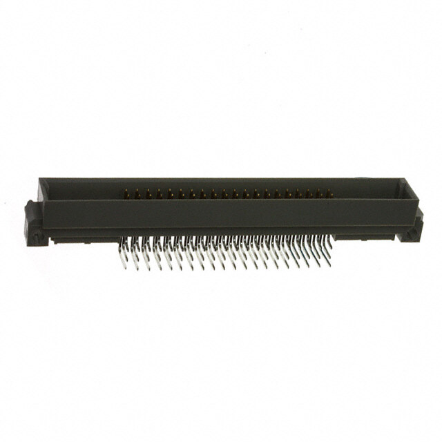
PT Connectors with Printed Circuit Board Contacts Box Mounting Receptacle (PT02) with PCB Contacts SR P.1T20 ± .005 Dia. M L Order by applicable part number in chart below; (TP) (.147 ± .005 Dia., size 24) add insert arrangement number. Refer to insert availability SP .150 ± .005 Dia. on pages 4-10. ■ (MMC) located within .0025 of (TP) R S 4 Holes A N (TP) K Z Receptacle Front View Receptacle Side View Part Number* SShizeell PT0C2o wntiathc tPsC B (TRP) +.0S11 +.0A01 +.0K21 MLax. +.M031 DNia. +.0Z40 -.010 -.005 -.010 -.000 Max. -.050 6 71-570120-XXX .469 .688 .348 .493 .825 .431 .323 .380 8 71-570121-XXX .594 .812 .473 .493 .825 .431 .449 .380 10 71-570122-XXX .719 .938 .590 .493 .825 .431 .573 .380 12 71-570123-XXX .812 1.031 .750 .493 .825 .431 .699 .380 14 71-570124-XXX .906 1.125 .875 .493 .825 .431 .823 .380 16 71-570125-XXX .969 1.219 1.000 .493 .825 .431 .949 .380 18 71-570126-XXX 1.062 1.312 1.125 .493 .825 .431 1.073 .380 20 71-570127-XXX 1.156 1.438 1.250 .650 1.076 .556 1.199 .286 22 71-570128-XXX 1.250 1.562 1.375 .650 1.076 .556 1.323 .286 24 71-570129-XXX 1.375 1.688 1.500 .683 1.109 .589 1.449 .253 All dimensions for reference only. Jam Nut Receptacle (PT07) S M H Z with PCB Contacts All lockwire holes are .044 Dia. Min. Order by applicable part number in chart below; add insert arrangement number. Refer to insert availability S J A on pages 4-10. R P K Receptacle Front View Receptacle Side View Part Number* SShizeell PT0C2o wntiathc tPsC B +.0H17 ±.0S10 A+ .D00ia1. J+ .F0l0a0t +.0K11 ±.M010 ThPi cPkanneesl s ThrRead +.0Z25 -.016 -.005 -.010 -.010 Min. Max. Class 2A -.035 6 71-533720-XXX .625 .812 .348 .405 .125 .696 .062 .125 .4375-28 UNEF .376 8 71-533721-XXX .750 .938 .473 .530 .125 .696 .062 .125 .5625-24 UNEF .376 10 71-533722-XXX .875 1.062 .590 .655 .125 .696 .062 .125 .6875-24 UNEF .376 12 71-533723-XXX 1.062 1.250 .750 .818 .125 .696 .062 .125 .8750-20 UNEF .376 14 71-533724-XXX 1.188 1.375 .875 .942 .125 .696 .062 .125 1.0000-20 UNEF .376 16 71-533725-XXX 1.312 1.500 1.000 1.066 .125 .696 .062 .125 1.1250-18 UNEF .376 18 71-533726-XXX 1.438 1.625 1.125 1.191 .125 .696 .062 .125 1.2500-18 UNEF .376 20 71-533727-XXX 1.562 1.812 1.250 1.316 .156 .884 .062 .250 1.3750-18 UNEF .367 22 71-533728-XXX 1.688 1.938 1.375 1.441 .156 .884 .062 .250 1.5000-18 UNEF .367 24 71-533729-XXX 1.816 2.062 1.500 1.556 .156 .917 .062 .250 1.6250-18 UNEF .334 All dimensions for reference only. * For RoHS compliance connectors with PCB contacts change “71”- to: “FL” designates conductive gray zinc nickel plating “93” designates black zinc cobalt plating 19
PTB SPB thru bulkhead receptacle L S PTB M R .120 ± .005 Dia. P (TP) (.147 ± .005 Dia., size 24) SPB .150 ± .005 Dia. 4 Holes R S A A (TP) K * PTB-XX-XXX * SPB-XX-XXX * To complete part number add desired arrangement number (refer to pages 4 and 5 for insert availability) and add “PS”; Example: PTB-18-32PS. If a rotation is required, use PTB-18-32PS and add W, X, Y or Z. Example: PTB-18-32 PSW. The socket end of the insert always appears at the “P” dimension end of shell. ■(MMC) located within .0025 of (TP) Receptacle Front View Receptacle Side View Shell R P Size (TP) S A K L M Max. +.001 +.016 +.010 ±.005 PTB SPB PTB SPB -.005 -.000 -.000 PTB SPB 6 .469 .641 .688 .953 .348 .625 1.050 .562 .125 .188 8 .594 .734 .812 1.047 .473 .625 1.050 .562 .125 .188 10 .719 .812 .938 1.125 .590 .625 1.050 .562 .125 .188 12 .812 .938 1.031 1.250 .750 .625 1.050 .562 .125 .188 14 .906 1.031 1.125 1.344 .875 .625 1.050 .562 .125 .188 16 .969 1.125 1.219 1.438 1.000 .625 1.050 .562 .125 .188 18 1.062 1.203 1.312 1.516 1.125 .625 1.050 .562 .125 .188 20 1.156 1.297 1.438 1.672 1.250 .781 1.330 .688 .125 .312 22 1.250 1.375 1.562 1.750 1.375 .781 1.330 .688 .125 .312 24 1.375 1.500 1.688 1.875 1.500 .781 1.330 .688 .125 .312 All dimensions for reference only. 20
PT hermetic Three shell styles are available in the hermetic PT bayonet series: • PTIH (MS3113H) • PT02H solder • PT07H (MS3114H) mounting receptacle These hermetic connectors are only available with solder cup or flat eyelet pin contacts in the MS/PT version. Socket contacts are available in some proprietary PT versions. Other design characteristics of the PT hermetic connector series are as follows: Shell sizes: 8 through 24 (tin plated) Contact count: 2 through 61. Refer to pages 4 and 5 for insert availability for hermetics. Current: 5.0 amp each #20 contact 10 amp each #16 contact 17 amp each #12 contact Contacts are tin plated for PT; gold is optional Dielectric Withstanding Voltage (sea level): 1500 volts (RMS) 60 cps, Service Rating I 2300 volts (RMS) 60 cps, Service Rating II box mounting receptacle Compression glass inserts, permanently lettered Helium Leakage: Less than 1.0 X 10⁻⁶ cc/sec. at 15 psi differential Physical Shock: 100 G’s Vibration: Exceeds MIL-E-5272 Procedure II Thermal Shock: No deterioration or failure after 5 cycles at –55°F to +257°F Intermateability: Mates with MS3116 and PT06 Refer to pages 4-10 for insert arrangement availability. jam nut receptacle 21
PTIH (MS3113H) hermetic solder mounting receptacle G L W A N .031 +.006 Z –.005 * PTIH-XX-XXX ** PTIY-XX-XXX ** MS3113H-XXCXXX † PTIH-XX-XXX (100) †† PTIY-XX-XXX (100) †† MS3113H-XXYXXX To complete part number see how to order on page 25. * Solder cup pin contacts without interfacial seal ** Solder cup pin contacts with interfacial seal † Flat eyelet pin contacts without interfacial seal †† Flat eyelet pin contacts with interfacial seal Recept. Receptacle Side View Front View Shell Size A Dia. L N Dia. W G Dia. Z +.001 +.025 +.001 +.001 Max. Max. -.005 -.016 -.005 -.010 6 .511 .348 .447 .438 .094 .386 8 .636 .473 .447 .562 .094 .386 10 .761 .590 .447 .672 .094 .386 12 .855 .750 .447 .781 .094 .386 14 .980 .875 .447 .906 .094 .386 16 1.105 1.000 .447 1.031 .094 .386 18 1.229 1.125 .447 1.156 .094 .386 20 1.323 1.250 .509 1.250 .094 .386 22 1.449 1.375 .509 1.375 .125 .418 24 1.574 1.500 .542 1.500 .125 .418 All dimensions for reference only. 22
PT02H hermetic box mounting receptacle S PT (TRP) .(.112407 ±± ..000055 DDiaia.., size 24) L W SP .150 ± .005 Dia. 4 Holes (TRP)S A N U Z * PT02H-XX-XXX ** PT02Y-XX-XXX † PT02H-XX-XXX (100) †† PT02Y-XX-XXX (100) To complete part number see how to order on page 25. * Solder cup pin contacts without interfacial seal ** Solder cup pin contacts with interfacial seal † Flat eyelet pin contacts without interfacial seal †† Flat eyelet pin contacts with interfacial seal ■ (MMC) located within .0025 of (TP) Recept. Front View Receptacle Side View Shell Size R S A Dia. K L N Dia. U Z +.001 +.025 +.001 +.011 (TP) ±.016 ±.015 Max. -.005 -.015 -.005 -.010 6 .469 .688 .348 .047 .494 .438 .062 .344 8 .594 .812 .473 .047 .494 .562 .062 .344 10 .719 .938 .590 .047 .494 .672 .062 .344 12 .812 1.031 .750 .047 .494 .781 .062 .344 14 .906 1.125 .875 .047 .494 .906 .062 .344 16 .969 1.219 1.000 .047 .494 1.031 .062 .344 18 1.062 1.312 1.125 .047 .494 1.156 .062 .344 20 1.156 1.438 1.250 .047 .556 1.250 .062 .344 22 1.250 1.562 1.375 .079 .556 1.375 .062 .377 24 1.375 1.688 1.500 .079 .588 1.500 .062 .377 All dimensions for reference only. 23
PT07H (MS3114H) hermetic jam nut receptacle S M Z H S A R P K * PT07H-XX-XXX ** PT07Y-XX-XXX ** MS3114H-XXCXXX † PT07H-XX-XXX (100) †† PT07Y-XX-XXX (100) †† MS3114H-XXYXXX To complete part number see how to order on page 25. * Solder cup pin contacts without interfacial seal ** Solder cup pin contacts with interfacial seal † Flat eyelet pin contacts without interfacial seal †† Flat eyelet pin contacts with interfacial seal Recept. Front View Receptacle Side View Shell H Hex A K M P Panel Thickness R Size S +.017 +.001 +.043 +.031 Thread Z Max. ±.016 -.016 -.005 -.016 -.000 Max. Min. Class 2A 6 .812 .625 .348 .094 .696 .125 .062 .4375-28 UNEF .206 8 .938 .750 .473 .094 .696 .125 .062 .5625-24 NEF .206 10 1.062 .875 .590 .094 .696 .125 .062 .6875-24 NEF .206 12 1.250 1.062 .750 .094 .696 .125 .062 .8750-20 UNEF .206 14 1.375 1.188 .875 .094 .696 .125 .062 1.0000-20 UNEF .206 16 1.500 1.312 1.000 .094 .696 .125 .062 1.1250-18 NEF .206 18 1.625 1.438 1.125 .094 .696 .125 .062 1.2500-18 NEF .206 20 1.812 1.562 1.250 .125 .884 .250 .062 1.3750-18 NEF .081 22 1.938 1.688 1.375 .125 .884 .250 .062 1.5000-18 NEF .081 24 2.062 1.812 1.500 .125 .917 .250 .062 1.6250-18 NEF .048 All dimensions for reference only. 24
PT, SP, MS/PT how to order PT,SP Ex: PT00A-20-41PW003 1. 2. 3. 4. 5. 6. 7. 8. Insert Connector Type Shell Style Service Class Shell Size Contact Configuration Insert Rotation Finish Arrangement PT 00 A 20 41 P W 003 1. Connector Type 3. Service Class 7. Insert Rotation PT standard olive drab, electrically conductive cadmium A General duty back shell No letter is required for normal position plate bayonet lock connector with solder contacts C Pressurized receptacle W electrically non-conductive, hard anodic coated bay- SP onet lock connector with solder contacts and larger E Environmental resisting open wire seal with grom- X Refer to page 6 flange and mounting holes for back panel mounting met and nut Y PTG plug with grounding fingers P Assembly with potting boot Z Adapter for cable glad for moisture proofing PG jacketed cables 2. Shell Style 8. Finish H Hermetic* without interfacial seal 00 Wall mounting receptacle SR Designates a strain relief clamp Y Hermetic* with interfacial seal 01 Cable connecting receptacle Indicate optional finishes as follows: 02 Box mounting receptacle 4. Shell Size 100 Suffix added for flat eyelet pin contacts in hermetic versions 06 Straight plug Shell sizes 6 - 24 available OR 07 Jam nut receptacle 005 * Anodic coating - Alumilite® (standard on “SP”) 08 90 degree plug cable support 5. Insert Arrangement 023 * Electroless nickel B thru bulkhead receptacle (pressurized) Refer to pages 4-10 for insert availability (Use only the number following the hyphen) 025 Black zinc cobalt plating I Solder mount receptacle (Hermetic only) 072 * Conductive gray zinc nickel plating 6. Contact Configuration 424 * Electroless nickel finish with strain relief P Pin contacts 470 Black zinc cobalt plating with strain relief S Socket contacts 725 Gray zinc nickel plating with strain relief For ordering connectors with printed circuit board contacts, see pg. 19. * RoHS Compliant finish MS/PT Note: Olive drab cadmium is the default plating. If required on SP MIL-DTL-26482, Series 1 type use suffix (003). Ex: MS3110E20-41PW 1. 2. 3. 4. 5. 6. 7. 8. Specification Contact Connector Type Shell Style Service Class Shell Size Insert Arrangment Insert Rotation Number Configuration MS 311 0 E 20 41 P W 1. Connector Type 4. Service Class 7. Contact Configuration MS Military standard E Environmental resisting connector P Pin contacts F Environmental resisting connectors S Socket contacts 2. Specification Number with strain relief For ordering connectors with printed circuit board Basic family number for J Clamp assembly for moisture proofing contacts, see pg. 19. 311 multi-jacketed cables, with strain relief MIL-DTL-26482, Series 1 solder type P Potted type with potting boot 8. Insert Rotation 3. Shell Style H Hermetic No letter is required for normal position 0 Wall mounting receptacle W 5. Shell Size 1 Cable connecting receptacle X Shell sizes 8 - 24 available Refer to page 6 2 Box mounting receptacle Y 3 Solder mount receptacle (Hermetic only) Z 6. Insert Arrangement 4 Jam nut receptacle Refer to pages 4-10 for insert availability 6 Straight plug (Use only the number following the hyphen) * Hermetic connectors are supplied with tin plated shells. Hermetic Version: ** This connector style is sometimes referred to as a cable connecting “plug”. It does, however, mate with either a In this version a letter replaces the hyphen between the straight or 90 degree plug. Shell Size and Insert Arrangement (Steps 5 and 6) Y Flat eyelet pin contacts C Solder cup pin co2nt5acts
Amphenol PT-SE, SP-SE, MS/PT-SE Proprietary/MIL-DTL-26482, Series 1 bayonet coupling and crimp termination Amphenol® SE crimp type miniature connectors provide performance and versatility needed for applications demanding high reliability and crimp removable contacts. wall mounting receptacle These crimp contacts are rear insertable/front release and are held in position by an MS approved spring tower retention system. The MS/PT-SE Series is qualified to MIL-DTL-26482, Series 1 and has all the outstanding design characteristics and quality of the PT Series. The SP-SE Series is a modification of the PT-SE, providing special shells with a cable wide mounting flange for back panel mounting. connecting receptacle* A corrosion resistant electrically conductive finish of cadmium plate with an olive drab chromate after-treatment is used on the PT-SE and MS/PT-SE. The SP-SE is given a durable non-conductive hard anodic “Alumilite”® coating which provides abrasion protection and resistance to corrosion. 500 hour corrosion resistance, RoHS compliant harsh environment conductive plating. Gray Zinc over an Electroless Nickel (Gray ZnNi) base, with a Light Gun box mounting Metal Gray appearance. receptacle Shell components for these series are aluminum. The dependable 5 key/ keyway polarization with bayonet lock coupling assures positive mating with no chance of cross plugging. Spring tension provided by a wave washer in the coupling nut ensures maintenance of interfacial seal between mating halves. Both the insert and main joint gasket are molded from resilient neoprene. straight plug This provides excellent moisture sealing at the gasket and superior electrical isolation of the contact in the insert. Both pins and sockets are machined from a copper alloy and are gold plated. This gold plating eliminates contact corrosion and offers an indefinite shelf life. Socket contacts for these series are closed entry design. Breakaway style plug is available in PT-SE crimp. jam nut receptacle The PT-SE, SP-SE and MS/PT-SE Series are intermateable and intermountable with all existing Miniature Cylindrical Series connectors. Refer to pages 4-10 for insert arrangement availability. * This connector style is sometimes referred to as a cable connecting “plug”. It does, however, mate with either a straight or 90 degree plug. 26
PT-SE, SP-SE, MS/PT-SE Contact Specifications Maximum Crimp Well Minimum Well Contact Size Test Current Millivolt Drop† Diameter Depth “SE”, 20 7.5 55 .049±.001 .267 MS / “E” 16 13.0 49 .067±.001 .236 open wire seal 12 23.0 42 .100±.002 .236 Service Rating Recommended Test Voltage AC (RMS), 60 cps Service Operating AC Rating Voltage at Sea Sea Level 50,000 ft. 70,000 ft. 110,000 ft. Level I 600 1,500 500 375 200 II 1,000 2,300 750 500 200 † Silver plated wire per MIL-DTL-26482 PT-SE and SP-SE Service Classes PT-SE and SP-SE connectors are available in the three service classes listed below. “SE” (SR), MS / “F” strain relief “SE” Open wire sealing - environmental resistant, clamp with a nut and grommet for moisture proofing individual wires “SE (SR)“ Strain relief clamp - environmental resistant strain relief clamp and grommet for moisture proofing individual wires; provides added wire bundle support “SP” Translucent nylon boot for retaining customer applied potting compounds; held in place by a threaded ring MS/PT-SE Service Classes MS-SE series connectors are available in the following certified service classes: “E” Open wire sealing - environmental resisting “SP”, connectors are supplied with a multi-hole MS / “P” potting boot grommet and clamping nut for moisture proofing individual open wires “F” Environmental resistant strain relief clamp and grommet for moisture proofing individual wires; provides added wire bundle support “P” Potting applications - these connectors are supplied with a translucent nylon boot for retention of customer applied potting compound 27
PT00 SE (MS3120) SP00 SE wall mounting receptacle S T Dia. R 4 Holes (TP) R S (TP) TERMINATION ASSEMBLIES “SE” Open Wire Seal “SP” Potting Boot “SE” (SR), MS / “F” Strain Relief L A N M K PT00SE-XX-XXX PT00SE-XX-XXX (SR) PT00SP-XX-XXX SP00SE-XX-XXX SP00SE-XX-XXX (SR) SP00SP-XX-XXX MS3120E-XX-XXX MS3120F-XX-XXX To complete part number see how to order on page 36. ■(MMC) located within .005 of (TP) Receptacle Front View Receptacle Side View M SShizeell (TRP) MSax. T± .D00ia5. A+ .D00ia1. ±.0K16 +-..000100 Panel TPh*ickness -.005 PT SP PT SP PT SP PT SP PT SP 8 .594 - .828 - .120 - .473 .062 .431 - .094 - 10 .719 .812 .954 1.141 .120 .150 .590 .062 .431 .462 .094 .125 12 .812 .938 1.047 1.226 .120 .150 .750 .062 .431 .462 .094 .125 14 .906 1.031 1.141 1.360 .120 .150 .875 .062 .431 .462 .094 .125 16 .969 1.125 1.234 1.453 .120 .150 1.000 .062 .431 .462 .094 .125 18 1.062 1.203 1.328 1.532 .120 .150 1.125 .062 .431 .462 .094 .125 20 1.156 1.297 1.453 1.688 .120 .150 1.250 .094 .556 .556 .219 .219 22 1.250 1.375 1.578 1.766 .120 .150 1.375 .094 .556 .556 .219 .219 24 1.375 1.500 1.703 1.891 .147 .150 1.500 .094 .589 .589 .219 .219 Class “SE”, MS/”E” Class “SE”(SR), MS/”F” Class “SP”, MS/”P” Shell Size L N Dia. G L N D Dia. L N Dia. Max. Max Dia. Max. Max. Max. Max. Max. 8 1.328 .560 .125 2.422 .781 - - - 10 1.328 .704 .188 2.422 .844 .444 1.656 .734 12 1.328 .825 .312 2.422 .969 .558 1.656 .858 14 1.328 .954 .375 2.422 1.094 .683 1.656 .984 16 1.328 1.080 .500 2.537 1.156 .808 1.656 1.110 18 1.328 1.204 .625 2.537 1.406 .909 1.656 1.234 20 1.359 1.330 .625 2.824 1.406 1.034 1.750 1.360 22 1.359 1.454 .750 2.824 1.594 1.159 1.750 1.484 24 1.422 1.580 .800 2.900 1.688 1.284 1.782 1.610 * Back panel mounting 28 All dimensions for reference only.
MF00 SE (MS3128) wall mounting receptacle T1 Dia. 4 Holes S R1 (TP) R (TP) (TRP) (TRP1)S T Dia. 4 Holes “SE” Open Wire Seal TERMINATION ASSEMBLIES MS / “F” Strain Relief L A N M K MF00SE-XX-XXX (SR) MF00SE-XX-XXX MS3128F-XX-XXX MS3128E-XX-XXX Receptacle Front View Receptacle Side View Shell A Dia. M Class MS/ ”E” Class MS/ “F” Size S T Dia. T1 Dia. K R R1 Max. ±.005 ±.005 +.001 ±.016 +.010 L N F G L N -.000 -.000 Max. Max. Min. Dia. Max. Max. 10 .719 .812 1.141 .120 .150 .590 .062 .462 1.328 .685 .297 .188 1.906 .891 12 .812 .938 1.266 .120 .150 .750 .062 .462 1.328 .813 .422 .312 1.906 1.016 14 .906 1.031 1.360 .120 .150 .875 .062 .462 1.328 .930 .547 .375 1.906 1.141 16 .969 1.125 1.453 .120 .150 1.000 .062 .462 1.328 1.057 .609 .500 2.000 1.203 18 1.062 1.203 1.532 .120 .150 1.125 .062 .462 1.28 1.175 .734 .625 2.000 1.469 20 1.156 1.297 1.688 .120 .150 1.250 .094 .556 1.359 1.301 .734 .625 2.172 1.469 22 1.250 1.375 1.766 .120 .150 1.375 .094 .556 1.359 1.428 .922 .750 2.172 1.656 24 1.375 1.500 1.891 .147 .150 1.500 .094 .589 1.422 1.533 .984 .800 2.234 1.750 All dimensions for reference only. 29
PT01 SE (MS3121) SP01 SE cable connecting receptacle S S TERMINATION ASSEMBLIES “SE” Open Wire Seal “SE” (SR), MS / “F” Strain Relief “SP”, MS / “P” Potting Boot L L A N A D N K K K PT01SE-XX-XXX PT01SE-XX-XXX (SR) PT01SP-XX-XXX SP01SE-XX-XXX SP01SE-XX-XXX (SR) SP01SP-XX-XXX MS3121E-XX-XXX MS3121F-XX-XXX MS3121P-XX-XXX Note: This connector style is sometimes referred to as a cable connecting “plug”. It does, however, mate with either a straight or 90 degree plug. To complete part number see how to order on page 36. Receptacle Receptacle Side View Front View Shell Class “SE”, MS/ ”E” Class “SE” (SR), MS/”F” Class “SP”, MS/”P” Size S A Dia. Max. +.001 K L N Dia. G Dia. L Max. N D Dia. L N Dia. ±.018 Max. Max. Max. Max. Max. -.005 8 .832 .473 .094 1.522 .560 .125 2.422 .828 - - - 10 .975 .590 .094 1.522 .685 .188 2.422 .891 .444 1.656 .734 12 1.068 .750 .094 1.522 .813 .312 2.422 1.016 .558 1.656 .858 14 1.162 .875 .094 1.522 .930 .375 2.422 1.141 .683 1.656 .984 16 1.256 1.000 .094 1.522 1.057 .500 2.537 1.203 .808 1.656 1.110 18 1.349 1.125 .094 1.522 1.175 .625 2.537 1.469 .909 1.656 1.234 20 1.475 1.250 .115 1.709 1.301 .625 2.824 1.469 1.034 1.750 1.360 22 1.599 1.375 .115 1.709 1.428 .750 2.824 1.656 1.159 1.750 1.484 24 1.729 1.500 .115 1.709 1.555 .800 2.900 1.750 1.284 1.782 1.610 All dimensions for reference only. 30
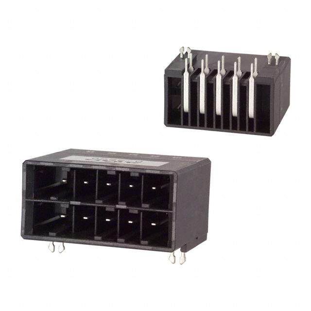
PT02 SE (MS3122) SP02 SE box mounting receptacle S L R (TP) M K R S A N (TP) T Dia. D 4 Holes PT02SE-XX-XXX SP02SE-XX-XXX MS3122E-XX-XXX To complete part number see how to order on page 36. ■ (MMC) located within .0025 of (TP) Receptacle Front View Receptacle Side View T M Shell S A D N R Dia. +.010 Size Max. Dia. Max. K L Dia. ±.005 -.000 +.001 ±.025 Max. +.011 PT SP PT SP PT SP -.005 PT SP PT SP -.000 8 .594 - .828 - .120 - .473 .312 - .062 1.358 .431 - .438 10 .719 .812 .954 1.141 .120 .150 .590 .312 .219 .062 1.296 .431 .462 .562 12 .812 .938 1.047 1.266 .120 .150 .750 .312 .219 .062 1.296 .431 .462 .688 14 .906 1.031 1.141 1.360 .120 .150 .875 .312 .219 .062 1.296 .431 .462 .812 16 .969 1.125 1.234 1.453 .120 .150 1.000 .312 .219 .062 1.296 .431 .462 .938 18 1.062 1.203 1.328 1.532 .120 .150 1.125 .312 .219 .062 1.296 .431 .462 1.062 20 1.156 1.297 1.453 1.688 .120 .150 1.250 .406 .344 .094 1.358 .556 .556 1.188 22 1.250 1.375 1.578 1.766 .120 .150 1.375 .406 .344 .094 1.358 .556 .556 1.312 24 1.375 1.500 1.703 1.891 .147 .150 1.500 .406 .344 .094 1.358 .589 .589 1.438 All dimensions for reference only. 31
MF02 SE (MS3127) box mounting receptacle T1 Dia. 4 Holes S L R1 (TP) M R (TP) K (TRP) (TRP1)S A N T Dia. D 4 Holes MF02SE-XX-XXX MS3127E-XX-XXX To complete part number see how to order on page 36. ■ (MMC) located within .0025 of (TP) Receptacle Front View Receptacle Side View Shell N A M Size Dia. R R1 S T T1 Dia. D K L +.010 +.011 Max. ±.005 ±.005 +.001 Max. ±.016 Max. -.000 -.000 -.005 10 .562 .719 .812 1.141 .120 .150 .590 .219 .062 1.266 .462 12 .688 .812 .938 1.266 .120 .150 .750 .219 .062 1.266 .462 14 .812 .906 1.031 1.360 .120 .150 .875 .219 .062 1.266 .462 16 .938 .969 1.125 1.453 .120 .150 1.000 .219 .062 1.266 .462 18 1.062 1.062 1.203 1.532 .120 .150 1.125 .219 .062 1.266 .462 20 1.188 1.156 1.297 1.688 .120 .150 1.250 .344 .094 1.328 .556 22 1.312 1.250 1.375 1.766 .120 .150 1.375 .344 .094 1.328 .556 24 1.438 1.375 1.500 1.891 .147 .150 1.500 .344 .094 1.328 .589 All dimensions for reference only. 32
PT06 SE (MS3126) SP06 SE straight plug S TERMINATION ASSEMBLIES “SE”, MS / “E” Open Wire Seal “SE” (SR), MS / “F” Strain Relief “SP”, MS / “P” Potting Boot L L L N G N D N Z pin contacts Z pin contacts Z pin contacts Z1 socket contacts Z1 socket contacts Z1 socket contacts PT06SE-XX-XXX PT06SE-XX-XXX (SR) PT06SP-XX-XXX SP06SE-XX-XXX SP06SE-XX-XXX (SR) SP06SP-XX-XXX PTG06SE-XX-XXX PTG06SE-XX-XXX (SR) PTG06SP-XX-XXX MS3126E-XX-XXX MS3126F-XX-XXX MS3126P-XX-XXX To complete part number see how to order on page 36. Plug Front View Plug Side View Class “SE”, MS/”E” Class “SE” (SR), MS/”F” Class “SP”, MS/”P” Shell Size S Dia. Z Z1 Max. ±.045 ±.045 L Max. N Max. G L N D L N Dia. Dia. Max. Max. Dia. Max. Max. 8* .734 .640 .579 1.328 .540 .125 2.413 .828 .327 1.750 .578 10 .859 .640 .579 1.328 .685 .188 2.413 .891 .444 1.750 .734 12 1.031 .640 .579 1.328 .813 .312 2.413 1.016 .558 1.750 .858 14 1.156 .640 .579 1.328 .930 .375 2.413 1.141 .683 1.750 .984 16 1.281 .640 .579 1.328 1.057 .500 2.528 1.203 .808 1.750 1.110 18 1.391 .640 .579 1.328 1.175 .625 2.528 1.469 .909 1.750 1.234 20 1.531 .640 .579 1.297 1.301 .625 2.753 1.469 1.034 1.750 1.360 22 1.656 .640 .579 1.297 1.428 .750 2.753 1.656 1.159 1.750 1.484 24 1.777 .640 .579 1.359 1.533 .800 2.830 1.750 1.284 1.766 1.610 * PT-SE, MS-SE and MS-SP only. All dimensions for reference only. 33
PT07 SE (MS3124) SP07 SE S H jam nut receptacle S TERMINATION ASSEMBLIES “SE”, MS / “E” Open Wire Seal “SE” (SR), MS / “F” Strain Relief “SP”, MS / “P” Potting Boot L L L M M M K K K R J A N J A F N J A G N R R P P P PT07SE-XX-XXX PT07SE-XX-XXX (SR) PT07SP-XX-XXX SP07SE-XX-XXX SP07SE-XX-XXX (SR) SP07SP-XX-XXX MS3124E-XX-XXX MS3124F-XX-XXX MS3124P-XX-XXX To complete part number see how to order on page 36. All lockwire holes are .044 Dia. Min. Receptacle Front View Receptacle Side View Shell Size H Hex S A+ .D00ia1. J+ .F0l0a0t +.0K11 M Panel ThPickness ThrRead Max. Max. ±.005 -.005 -.010 -.010 Min. Max. Class 2A 8 .767 .954 .473 .530 .125 .696 .062 .125 .5625-24 UNEF 10 .892 1.078 .590 .655 .125 .696 .062 .125 .6875-24 NEF 12 1.079 1.266 .750 .818 .125 .696 .062 .125 .8750-20 UNEF 14 1.205 1.391 .875 .942 .125 .696 .062 .125 1.0000-20 UNEF 16 1.329 1.516 1.000 1.066 .125 .696 .062 .125 1.1250-18 NEF 18 1.455 1.641 1.125 1.191 .125 .696 .062 .125 1.2500-18 NEF 20 1.579 1.828 1.250 1.316 .156 .884 .062 .250 1.3750-18 NEF 22 1.705 1.954 1.375 1.441 .156 .884 .062 .250 1.5000-18 NEF 24 1.829 2.078 1.500 1.556 .156 .917 .062 .250 1.6250-18 NEF Class “SE”, MS/”E” Class “SE” (SR), MS/”F” Class “SP”, MS/”P” Shell Size L N F G Dia. L N G L N Dia. Max. Max. Min. Free Max. Max. Dia. Max. Max. 8 1.438 .749 .234 .125 1.922 .828 - - - 10 1.438 .874 .297 .188 1.922 .891 .444 1.656 .734 12 1.438 .999 .422 .312 1.922 1.016 .558 1.656 .858 14 1.438 1.124 .547 .375 1.922 1.141 .683 1.656 .984 16 1.438 1.249 .609 .500 2.000 1.203 .808 1.656 1.110 18 1.438 1.374 .734 .625 2.000 1.469 .909 1.656 1.234 20 1.625 1.530 .734 .625 2.172 1.469 1.034 1.922 1.360 22 1.625 1.655 .922 .750 2.172 1.656 1.159 1.922 1.484 24 1.688 1.780 .984 .800 2..234 1.750 1.284 1.951 1.610 All dimensions for reference only. 34
PT08 SE SP08 SE 90 degree plug G “SE” Open Wire Seal, “SE” (SR) Strain Relief TERMINATION ASSEMBLIES “SP” Potting Boot 75 degrees L L E B A H PT08SE-XX-XXX PT08SP-XX-XXX SP08SE-XX-XXX SP08SP-XX-XXX PT08SE-XX-XXX (SR) D SP08SE-XX-XXX (SR) K C To complete part number see how to order on page 36. All lockwire holes are .044 Dia. Min. Plug Front View Plug Side View Shell Size C E G Dia. B D L A H K L +.010 +.047 Max. ±.031 ±.062 Max. ±.025 ±.015 ±.015 Max. -.025 -.025 10 .921 .749 .170 1.191 .393 2.137 .547 .438 .562 2.031 12 1.046 .812 .264 1.191 .450 2.222 .625 .516 .688 2.093 14 1.171 .905 .310 1.254 .519 2.370 .734 .625 .781 2.203 16 1.297 1.030 .330 1.316 .583 2.572 .750 .656 .890 2.250 18 1.422 1.015 .444 1.562 .621 2.680 .781 .703 1.000 2.296 20 1.562 1.077 .510 1.625 .683 2.753 .859 .766 1.125 2.343 22 1.672 1.139 .515 1.719 .739 2.799 .906 .812 1.234 2.390 24 1.797 1.250 .656 1.750 .787 3.037 1.181 .918 1.374 2.624 All dimensions for reference only. 35
PT-SE, SP-SE, MS/PT-SE how to order PT-SE, SP-SE Ex: PT00SE-20-41PW003 1. 2. 3. 4. 5. 6. 7. 8. Insert Connector Type Shell Style Service Class Shell Size Contact Configuration Insert Rotation Finish Arrangement PT 00 SE 20 41 P W 003 1. Connector Type 3. Service Class 7. Insert Rotation PT standard olive drab, electrically conductive cadmium SE Environmental crimp No letter is required for normal position plate bayonet lock connector with solder contacts SP potted type crimp W standard olive drab, electrically conductive cadmium MF plated, bayonet lock connector with dual mounting Both of the above are Amphenol proprietary versions of the X Refer to page 6 holes, and MILDTL-26482, Series 1 crimp contact connector and offer Y crimp contacts 15 lbs. contact retention for size 20 contacts; 25 lbs. for size Z 16 contacts. electrically non-conductive, hard anodic coated bay- SP onet lock connector with solder contacts and larger adapter for cable gland for moisture proofing PG flange and mounting holes for back panel mounting jacketed cables SQ Braided shield termination 8. Finish 2. Shell Style G Heatshrink termination SR Designates a strain relief clamp 00 Wall mounting receptacle Indicate optional finishes as follows: 01 Cable connecting receptacle 4. Shell Size 100 Suffix added for flat eyelet pin contacts in hermetic versions 02 Box mounting receptacle Shell sizes 8 - 24 available OR 06 Straight plug 005 * Anodic coating - Alumilite® (standard on “SP”) 07 Jam nut receptacle 5. Insert Arrangement 023 * Electroless nickel 08 90 degree plug Refer to pages 4-10 for insert availability (Use only the number following the hyphen) 025 Black zinc cobalt plating 072 * Conductive gray zinc nickel plating 6. Contact Configuration 424 * Electroless nickel finish with strain relief P Pin contacts 470 Black zinc cobalt plating with strain relief S Socket contacts 725 Gray zinc nickel plating with strain relief * RoHS Compliant finish MS/PT-SE MIL-DTL-26482, Series 1 Note: Olive drab cadmium is the default plating. If required on SP type use suffix (003). Ex: MS3120E20-41PW 1. 2. 3. 4. 5. 6. 7. 8. Specification Contact Connector Type Shell Style Service Class Shell Size Insert Arrangement Insert Rotation Number Configuration MS 311 0 E 20 41 P W 1. Connector Type 4. Service Class 7. Contact Configuration MS Military standard E Environmental resisting connector P Pin contacts F Environmental resisting connectors with strain relief S Socket contacts 2. Specification Number P Potted type with potting boot 312 basic family for MIL-DTL-26482, Series 1 crimp type SQ Braided shield termination 8. Insert Rotation G Heatshrink termination No letter is required for normal position 3. Shell Style W 0 Wall mounting receptacle X 5. Shell Size Refer to page 6 1 Cable connecting receptacle* Y 2 Box mounting receptacle Shell sizes 8 - 24 available Z 4 Jam nut receptacle 6. Insert Arrangement * This connector style is sometimes referred to as a cable 6 Straight plug connecting “plug”. It does, however, mate with either a Refer to pages 4-10 for insert availability straight or 90 degree plug. 7 box mounting receptacle with dual mounting holes (Use only the number following the hyphen) 8 wall mounting receptacle with dual mounting holes 36
PT & SP accessories – sealing plugs, flange gaskets, potting boots SEALING PLUGS- FOR PT & SP A B Contact Amphenol® MS C Color Dia. Dia. Size Part Number Number ±.010 Code ±.010 ±.005 C B 12 10-405996-12 MS27488-12 .121 .171 .564 Yellow DIA .135 +.030 –.025 16 10-405996-16 MS27488-16 .083 .133 .564 Blue A DIA 20 10-405996-16 MS27488-20 .060 .090 .564 Red How to Order: Order by 10- (Proprietary) or MS part number as shown in chart SEALING PLUG above. MS27488-XX 10-405996-XX MOUNTING FLANGE GASKETS – FOR PT & SP PT & SP .130 DIA SIZE 6 TO 22 PT SP 10-101949 .156 DIA SIZE 24 10-101949 10-150949 .160 DIA 10-150949 10-150949 Shell Size F R S R S T +.016 ±.010 ±.010 ±.010 ±.010 ±.008 -.000 6 .469 .688 .641 .953 .375 .024 8 .594 .812 .734 1.047 .500 .024 T 10 .719 .938 .812 1.125 .625 .024 12 .813 1.031 .938 1.250 .750 .024 14 .906 1.125 1.031 1.344 .875 .024 16 .969 1.219 1.125 1.438 1.000 .024 MOUNTING FLANGE GASKET 18 1.063 1.312 1.203 1.516 1.125 .024 10-101949-XX 10-150949-XX 20 1.156 1.438 1.297 1.672 1.250 .024 22 1.250 1.563 1.375 1.750 1.375 .024 24 1.375 1.688 1.500 1.875 1.500 .024 How to Order: For PT: 10-101949-XX (complete order number with desired shell size). For SP: 10-150949-XX (complete order number with desired shell size). 75° POTTING BOOTS – FOR PT & SP Shell B D E L Size Max. ±.015 ±.015 Max. B E 15º 8 .433 .312 .438 .766 REF 10 .493 .438 .562 .830 D 12 .552 .516 .688 .861 14 .643 .625 .781 .916 L 16 .658 .656 .890 .936 18 .689 .703 1.000 .959 20 .750 .766 1.125 1.052 75° POTTING BOOT 22 .794 .812 1.234 1.073 10-101988-XX 24 1.070 .918 1.374 1.310 How to Order: 10-101988-XX (complete order number with desired shell size). All dimensions for reference only 37
PT & SP CLASS “E” STRAIN RELIEF CLAMP – FOR PT & SP Shell B C Thread D G L accessories – clamps Size Max. Class 2B Min. Max. Max. 8 .550 6-32 NC .240 .812 .930 10 .675 6-32 NC .302 .875 .930 12 .803 6-32 NC .428 1.000 .930 14 .920 6-32 NC .552 1.125 .930 16 1.047 6-32 NC .615 1.188 1.062 L 18 1.165 8-32 NC .740 1.438 1.062 20 1.291 8-32 NC .740 1.438 1.093 22 1.418 8-32 NC .928 1.719 1.093 B D G 24 1.533 8-32 NC .928 1.719 1.093 How to Order: 10-101971-XX X C Add desired Add desired finish suffix† shell size “3” designates olive drab cadmium “5’ designates Alumilite® CLASS “E” STRAIN RELIEF CLAMP Not for use with jam nut style connectors 10-101971-XX CLASSES “A” & “P” STRAIN RELIEF CLAMP – FOR PT & SP L Shell B C Thread D G +.010 Size Max. Class 2B Min. Max. -.020 8 .540 6-32 NC .240 .812 .843 10 .665 6-32 NC .302 .875 .843 12 .793 6-32 NC .428 1.000 .843 14 .910 6-32 NC .552 1.125 .843 L 16 1.037 6-32 NC .614 1.188 .975 18 1.155 8-32 NC .740 1.438 .975 20 1.281 8-32 NC .740 1.438 1.007 B D G 22 1.408 8-32 NC .928 1.719 1.007 24 1.533 8-32 NC .938 1.719 1.007 C How to Order: 10-101980-XX X Add desired Add desired finish suffix† CLASSES “A” & “P” STRAIN shell size “3” designates olive drab cadmium RELIEF CLAMP “5’ designates Alumilite® 10-101980-XX Not for use with jam nut style connectors CLASS “A” CABLE CLAMPS – FOR PT & SP Shell Amphenol® A B C V Size Part Number ±.031 Max. Dia. Min. Thread 10 97-3057-1004 .795 .842 .3125 .6250-24 12 97-3057-1007 .850 .995 .4375 .7500-20 14 97-3057-1008 .920 1.120 .5625 .8750-20 16 97-3057-1010 .920 1.216 .6250 1.0000-20 V Thread 18/20 97-3057-1012 .927 1.403 .7500 1.1875-18 22/24 97-3057-1016 1.015 1.683 .9375 1.4375-18 How to Order: Order by 97-3057-XXXX number listed above. Standard finish is olive B drab zinc alloy. Consult Amphenol, Sidney, NY for alternate finishes. † Standard accessory finishes are “3” olive drab cadmium for PT and MS/PT types, “5” Alumilite® for SP types. Electroless nickel plating is also available on some items; consult Amphenol, Sidney, NY C A All dimensions for reference only. CLASS “A” CABLE CLAMP 97-3057-XXXX 38
PT, SP, MS/PT accessories – protection caps RECEPTACLE PROTECTION CAPS – FOR PT, SP, MS/PT PLUG PROTECTION CAPS – FOR PT, SP, MS/PT B C .140 +.010 L L DIA –.005 FOR SIZE 24 .125 +.010 +.010 –.005 G N DIA .140 FOR SIZE 6-22 X X RECEPTACLE PROTECTION CAP PLUG PROTECTION CAP FOR PT, SP, MS/PT CONNECTORS FOR PT, SP, MS/PT CONNECTORS 10-101960-XXX 10-101961-XXX 10-101964-XXX MS3180-XXX MS3181-XXX (Cable Connecting MS3181-XXX 10-101957-XXX (Wall Receptacle) Receptacle) (Jam Nut Recptacle) B Dia. C Dia. G L X X N Dia. L Dia. X X Shell Shell +.010 +.010 Dia. +.020 Std. & MS MS only +.001 +.025 Std. & MS MS only Size Size -.000 -.000 Max. -.000 RA, CA, NA RAL/CAL/NAL -.005 -.015 CA, RA CAL/ RAL 6 .328 .454 .577 .563 3.000 5.000 6 .348 .532 3.000 5.000 8 .454 .578 .706 .563 3.000 5.000 8 .473 .532 3.000 5.000 10 .578 .703 .816 .563 3.000 5.000 10 .590 .532 3.000 5.000 12 .703 .891 1.000 .563 3.500 5.000 12 .750 .532 3.500 5.000 14 .844 1.016 1.128 .563 3.500 5.000 14 .875 .532 3.500 5.000 16 .969 1.141 1.257 .563 3.500 5.000 16 1.000 .532 3.500 5.000 18 1.094 1.266 1.367 .563 3.500 5.000 18 1.125 .532 3.500 5.000 20 1.219 1.391 1.496 .563 4.000 5.000 20 1.250 .594 4.000 5.000 22 1.343 1.516 1.624 .563 4.000 5.000 22 1.375 .594 4.000 5.000 24 1.453 1.614 1.747 .603 4.000 5.000 24 1.500 .627 4.000 5.000 How to Order Proprietary Receptacle Caps: How to Order Proprietary Plug Caps: 10-101957-XX X Wall Receptacle Caps: 10-101960- XX X Add desired shell size Cable Connecting Receptacle Caps: 10-101961- XX X Add desired finish suffix† Jam Nut Receptacle Caps: 10-101964- XX X “FL” designates gray zinc nickel Add desired shell size “3” designates olive drab cadmium Add desired finish suffix† “5” designates Alumilite® “FL” designates gray zinc nickel Proprietary caps are supplied with standard bead chains only (as “3” designates olive drab cadmium shown in drawing at left). For other chain options an MS version “5” designates Alumilite® cap should be ordered. Proprietary caps are supplied with standard bead chains only (as shown in drawing at left). For other chain options, an MS version cap should be How to Order ordered. MS Version Plug Caps: MS3180- XX -CA for sash chain How to Order MS Version Receptacle Caps: -CAL for long sash chain Wall Receptacle Caps: MS3181- XX -CA for sash chain -RA for rope chain -CAL for long sash chain Shell Size -RAL for long rope chain -RA for rope chain -RAL for long rope chain Jam Nut Recept. Caps: MS3181- XX -NA for sash chain -NAL for long sash chain Shell size MS versions are supplied with standard anodize finish only. For other finish options a proprietary cap should be ordered. 39
PT & SP accessories – dummy receptacles, “O” rings, plastic dust caps DUMMY RECEPTACLES – FOR PT, SP, MS/PT Proprietary S .150 DIA. +–..000042 M Shell K +.M030 +.0N01 Version MS Version R 4 HOLES K Size ±.010 -.000 -.005 R S R1 S1 ±.005 ±.010 (TP) (TP) 8 .062 .462 .473 .734 1.047 .594 .828 R S N 10 .062 .462 .590 .812 1.125 .719 .954 12 .062 .462 .750 .938 1.250 .812 1.047 14 .062 .462 .875 1.031 1.344 .906 1.141 16 .062 .462 1.000 1.125 1.438 .969 1.234 DUMMY RECEPTACLE FOR PT, SP, MS/PT CONNECTORS 18 .062 .462 1.125 1.203 1.516 1.062 1.328 MS3115-XXX 20 .062 .556 1.250 1.297 1.672 1.156 1.453 10-150921-XXX 22 .062 .556 1.375 1.375 1.750 1.250 1.578 24 .062 .589 1.500 1.500 1.875 1.375 1.703 How to Order Proprietary Dummy Receptacles: 10-150921-XX X Add desired shell size Add desired finish suffix† “FL” designates gray zinc nickel “3” designates olive drab cadmium “5” designates Alumilite® How to Order MS Version Dummy Receptacles: MS3115-XX X Add desired shell size Add desired finish suffix† -A designates Alumilite® -L designates electroless nickel -W designates olive drab cadmium PLASTIC DUST CAPS – FOR PT, SP How to Order Plastic Dust Caps: Plug Plastic Dust Receptacle Plastic Shell Size Cap Dust Cap To the basic order number add the dust cap size to 6 10-70500-8 10-70506-8S match connector plug or receptacle shell size, as shown in the tables above. 8 10-70506-12 10-70506-10 Example: 10-70506-12 would be the correct order number for a plastic dust cap for a PT00 receptacle, shell size 10. 10 10-70500-12 10-70506-12 12 10-70506-16 10-70506-14 14 10-70506-18 10-70506-16 16 10-70506-20 10-70506-18 18 10-70506-22 10-70506-20 20 10-70506-24 10-79506-22 22 10-70524-1 10-70506-24 24 10-70506-28 10-70524-1 All dimensions for reference only. 40
PT accessories glands Nylon Cable Glands Metal Cable Glands Material: Nylon 66 (UL Approved 94V-2) DUMMY RECEPTACLES – FOR PT, SP, MS/PT Material: Brass with Nickel; Brass with Tin/Nickel Seal ring: UL 94V-2 (UL Approved 94V-2) Clamping: UL approved PA6, 94V-0 Thread Type: Metric; PG, NPT Seal Ring: UL 94V-2 (UL approved NBR, 94V-2;UL approved Temp Range: Static: -40° to +100°C DOW CORNING RUBBER, 94V-0 Dynamic: -20° to +80°C Thread Type: Metric, PG, NPT Short Term: +120° Protective: IP68 (tighten with o-ring) Current Colors: Gray, Black Temp Range: -40° to +100°C Torque Value (N-M) of hex and cap nuts: 3.0-4.5 N-M M12, M16, M20 are UL recognized under file #E339605 Cable Thread Clamp Spanner Cable Thread Clamp Spanner M “d” Thread M “d” AIGO Part Thread “A” Range “L” “H” “S” AIGO Part Range “L” “H” “S” (mm) “A” (mm) (mm) (mm) (mm) (mm) (mm) (mm) (mm) (mm) AIO-CSM12 M12 x1.5 8 3-6.5 8 20 15 AIO-CSJM12 M12x1.5 6.5 3-6.5 6.2 15 14 AIO-CSM16 M16 x 1.5 8 4-8 8 22 19 AIO-CSJM14 M14x1.5 8 4-8 5 19 15 AIO-CSJM16 M16x1.5 9 6-9 6.3 20 18 AIO-CSM18 M18 x 1.5 10 5-10 9 25 22 AIO-CSJM18 M18x1.5 10 5-10 7 20 22 AIO-CSM18 M20 x 1.5 12 6-12 9 30 24 AIO-CSJM20 M20x1.5 12 6-12 8.3 20 22 AIO-CSM20 M22 x 1.5 14 10-14 10 30 27 AIO-CSJM22 M22x1.5 14 10-14 8 24 24 AIO-CSM22 M24 x 1.5 14 10-14 10 30 27 AIO-CSJM24 M24x1.5 14 10-14 8 24 27 AIO-CSM24 M25 x 1.5 18 13-18 10 30 33 AIO-CSJM25 M25x1.5 18 13-18 7.8 23 30 AIO-CSJM27 M27x1.5 18 13-18 8 26 30 AIO-CSM25 M30 x 2.0 18 13-18 11 33 33 AIO-CSJM30 M30x2.0 18 13-18 8 26 32 AIO-CSM30 M32 x 1.5 25 18-25 11 38 42 AIO-CSJM32 M32x1.5 25 18-25 10 27 40 AIO-CSM32 M33 x 2.0 25 18-25 11 39 42 AIO-CSJM36 M36x2.0 25 18-25 10 34 40 AIO-CSM33 M40 x 1.5 32 22-32 13 48 54 AIO-CSJM40 M40x1.5 32 22-32 10 39 50 AIO-CSM40 M50 x 1.5 38 32-38 14 50 60 AIO-CSJM50 M50x1.5 38 32-38 11 39 60 AIO-CSJM63 M63x1.5 44 37-44 12 43 67 AIO-CSM50 M72 x 2.0 57 51-57 16 75 80 AIO-CSJM72 M72x1.5 52 46-52 16 47 75 AIO-CSM72 NPT1/2” 12 6-12 13.6 28 24 AIO-CSJM80 M80x2.0 60 52-60 20 57 90 AIO-CSIN1/2 NPT 3/4” 18 13-18 14.1 32 33 AIO-CSJM90 M90x2.0 70 62-70 20 57 100 AIO-CSIN3/4 NPT 1”1/2” 32 22-32 17.3 50 54 AIO-CSJIN1/2 NPT 1/2” 12 6-12 13.6 25 24 AIO-CSJIN3/4 NPT 3/4” 18 13-18 14.1 26 30 AIO-CSIN3/2 G 1/2” 12 6-12 9 26 24 AIO-CSJIN5/4 NPT 1”1/4” 32 22-32 17.3 41 50 AIO-CSGIN3/4 G 3/4” 18 13-18 11 27 33 AIO-CSJIN3/2 NPT 1”1/2” 32 22-32 17.3 46 50 AIO-CSGIN1 G1” 25 18-25 11 33 42 AIO-CSJIN2 NPT2” 44 37-44 17.7 46 65 AIO-CSGIN5/4 G1”1/4 28 21-28 13 48 54 AIO-CSJIN5/2 NPT2 1/2” 52 46-52 23.7 58 80 AIO-CSGIN3/2 G1”1/2” 32 22-32 13 48 54 AIO-CSJIN3 NPT3” 70 62-70 26 58 100 AIO-CSJGIN1/2 G1/2” 12 6-12 8 24 24 AIO-CSGIN5/2 G2”1/2” 57 51-57 14 75 80 AIO-CSJGIN3/4 G3/4” 18 13-18 8 27 30 AIO-CSPG7 PG7 6.5 3-6.5 8 20 15 AIO-CSJGIN1 G1” 25 18-25 10 34 40 AIO-CSPG9 PG9 8 4-8 8 22 19 AIO-CSJGIN5/4 G1”1/4” 32 22-32 10 39 50 AIO-CSPG11 PG11 10 5-10 8 24 22 AIO-CSJGIN3/2 G1”1/2” 32 22-32 10 39 50 AIO-CSJGIN2 G2” 44 37-44 12 44 65 AIO-CSPG13.5 PG13.5 12 6-12 9 26 24 AIO-CSJGIN 5/2 G2 1/2” 52 46-52 16 47 82 AIO-CSPG16 PG16 14 10-14 10 28 27 AIO-CSJPG7 PG7 6.5 3-6.5 6 18 14 AIO-CSPG21 PG21 18 13-18 11 33 33 AIO-CSJPG9 PG9 8 4-8 7 21 18 AIO-CSPG29 PG29 25 18-25 11 38 42 AIO-CSJPG11 PG11 10 5-10 7 20 22 AIO-CSJPG13.5 PG13.5 12 6-12 8 24 22 AIO-CSPG36 PG36 32 22-32 13 48 54 AIO-CSJPG16 PG16 14 10-14 8 25 24 AIO-CSPG42 PG42 38 32-38 14 52 60 AIO-CSJPG21 PG21 18 13-18 8 26 30 AIO-CSJPG36 PG36 32 22-32 10 38 50 For additional information on other products available refer to our AIO-CSJPG42 PG42 38 32-38 11 42 60 Cord grips & Cable Glands, Catalog 12-055 AIO-CSJPG48 PG48 44 37-44 12 44 65 41
Application Tools “SE” The following data includes information pertaining to the application tools for crimping, inserting and removing size 20, 16, and 12 contacts incorporated in Amphenol® Miniature Cylindrical Connectors. All crimping tools included are the “full cycling” type, and when used as specified by the manufacturer, provide reliable crimped wire to contact termination. Tool frames and turret heads are available from approved tool manufacturers; consult Amphenol, Sidney, NY for listings. Assembly instructions are available online at www.amphenol-industrial.com See the following: L-786 for SE assembly instructions L-555 for solder type instructions CRIMPING TOOLS FOR PT-SE, SP-SE, MS/PT-SE (MIL-DTL-26482, Series 1) Connectors MS Tool Part Number Contact Size Tool From Turret Head 20 M22520/1-01 M22520/1-02 16 M22520/1-01 M22520/1-02 12 M22520/1-01 M22520/1-02 INSERTION/REMOVAL TOOLS FOR PT-SE, SP-SE, MS/PT-SE (MIL-DTL-26482, Series 1) Connectors Insertion Tool Removal Tool Contact Size MS Amphenol® Amphenol® MS Amphenol® Part Number Contact Contact Insertion Part Number Con- Contact Contact Removal Insertion Pliers Tool tact Insertion Tool Removal Tool Tool 20 11-8107-20 11-7401-20 M81969/17-03 11-7880-20 M81969/19-07 16 11-8107-16 11-7401-16 M81969/17-04 11-7880-16 M81969/19-08 12 - - M81969/17-05 - M81969/19-09 42
Contacts - Power and Thermocouple Crimp for miniature cylindrical connectors The following tables provide part number information for crimp contacts used in Amphenol® Miniature Cylindrical Connectors. For additional information, consult Amphenol, Sidney, NY. CRIMP CONTACTS for MIL-DTL-26482, Series 1 (PT-SE, SP-SE) Connectors Pins Sockets Accommodates Contact Size Wire Size Amphenol® Amphenol® MS Number Proprietary MS Number Proprietary Number Number 20, 22 & 24 20 M39029/31-240 10-683787-20P M39029/32-259 10-731210-3D1 AWG 16, 18 & 20 16 M39029/31-228 10-683788-16P M39029/32-247 10-679379-16D AWG 12 12 & 14 AWG M39029/31-235 10-807100-125 M39029/32-254 10-807103-125 20-16 16 AWG 10-330930-20F 10-807155-205 16-20 20 AWG 10-330932-16F 10-330933-16F 12-10 12 AWG 10-330938-12F 10-330939-12F THERMOCOUPLE CONTACTS for Miniature Connectors Pins Sockets Size Material Proprietary Part Number Proprietary Part Number SE SE Chromel 10-330940-21P 10-330940-21S 16 Crimp Termination Alumel 10-330940-22P 10-330940-22S Chromel 10-330940-1P 10-330940-1S Alumel 10-330940-2P 10-330940-2S 20 Crimp Termination Iron 10-330940-3P 10-330940-3S Constantan 10-330940-4P 10-330940-4S See L-776 for thermocouple contact termination instructions. These are online at www.amphenol-industrial.com For PCB contacts for miniature connectors, see page 20. 43
Coaxial Contacts for miniature cylindrical connectors Amphenol® Miniature Connectors can incorporate shielded coax contacts. The Miniature family is built around MIL-DTL-26482 specifications, with Mil-approved and proprietary styles offered. Normal operating voltage for Miniature cylindricals with power only contacts is up to 1,000 VAC (RMS) at sea level. Table 1: Miniature Cylindricals offer these features for contact termination flexibility: • Several insert arrangements that can incorporate: Solder Coax Contact for use in Miniature Solder Type Connectors • Size 8 & 12 Crimp Coax contacts for Crimp type • Size 8 & 12 Solder Coax contacts for Solder type • Wide selection of connector shell styles and sizes • Standard power contact options within the various connector styles include: solder type, crimp front release, crimp rear release • Coax contacts are designed to the same high performance standards as power contacts. Coax and power contacts may be intermixed with no degradation of connector reliability. • No mis-mating or cross-plugging with insert rotation and keyway polarization. Table 2: GENERAL ORDERING INFORMATION Amphenol Miniature Cylindricals are normally supplied with a full complement of power contacts, separately packaged. Coax contacts are ordered by part number as referenced in the part number charts on the following pages of this catalog, and are substituted for the power contacts at the time of the cable or equipment assembly. If the application is for coax only, the connector may be ordered less contacts and no power contacts will be supplied. Pin Crimp Coax Contact for use in Miniature Crimp SE Type Connectors Installation instructions for the coax contacts for Miniature Connectors are provided in Amphenol documents as follows: L-633 for solder type; L-613 for SE type. HOW TO ORDER: A. Select the coax contacts designed for the cable being used from the applicable charts in this catalog for each Miniature type (solder, SE). B. Select a connector insert from those shown on pages 4-5 which will accommodate the quantity and size of coaxial contacts needed plus any power contacts required. Note: Size 8S and 12S contacts are used with connector inserts through shell size 18 only. For larger connector shell sizes, use size 8L contacts. Socket Crimp Coax Contact C. Determine the Miniature Cylindrical type, shell style, finish, for use in Miniature Crimp SE Type Connectors service class and insert rotation required for your application. D. Consult Amphenol, Sidney NY with the pertinent cable, contact, insert arrangement and connector style choices for complete connector part number. 44
Coaxial Contacts for miniature cylindrical connectors, cont. Amphenol® Coaxial Contacts designed for use TYPICAL MINIATURE CRIMP COAX in Miniature Cylindrical Connectors offer the same SOCKET CONTACT has crimp socket outer durability advantages and design benefits for reliable contact with a solder pin inner contact interconnection as the Amphenol coax contacts used in high performance D38999 connectors. A variety of military and commercial shielded cables are accommodated within the miniature cylindrical series. Amphenol supplies coax contacts for solder and crimp SE connector styles. Other features of the coax for miniature cylindricals include: • Miniature coax design has an outside nut within the assembly for fast, reliable assembly of contact to cable. • All types feature solder style inner contacts and crimp style outer contacts for reliable cable termination • Miniature coax crimp type contacts are designed for use in Miniature crimp series connectors • Miniature coax solder type contacts are designed TYPICAL MINIATURE CRIMP COAX PIN for use in Miniature solder series connectors. These CONTACT has crimp pin outer contact with a solder socket inner contact come pre-installed into the solder connector. TYPICAL ELECTRICAL PERFORMANCE Size 8 and 12 Coax Contacts Contact Resistance: Center @ 1 Amp, 170 millivolts max. voltage drop @ 25°C Outer @ 12 Amps, 150 millivolts max. voltage drop @ 25°C Dielectric Withstanding Voltage: Size 8: 1,300 VAC Rms @ sea level Size 12: 1,000 VAC Rms @ sea level Size 8 & 12: 250 VAC Rms @ 50,000 ft. Insulation Resistance 5,000 megohms minimum @ 25°C Typical VSWR for size 8 & 12 PT-SE Types II & III only: 1.2 + .12F (GHz) up to 10 GHz EXPLANATION OF TYPE CLASSIFICATIONS: PT-SE Type I is moisture seal design with internal O-ring. PT-SE Type II is 50 ohm impedance matched version. Contacts terminated to other than 50 ohm cables are therefore not matched. PT-SE Type III is 50 ohm contact, non-serviceable after assembly. Solders are non-impedance matched contacts. CONTACT FINISHES: Suffix Finish 1 0.00020 min. silver over copper flash 2 0.00005 min. gold (Knoop hardness 130-200) over silver 3 0.00010 min. gold (Knoop hardness 130-200) over silver 4 0.00010 min. gold (Knoop hardness 130-200) over copper 5 0.00005 min. gold (Knoop hardness 130-200) over nickel E 0.00005 min. gold (Knoop hardness 90 max.) over copper F 0.00005 min. gold (Knoop hardness 130-200) over copper H 0.00010 min. gold (Knoop hardness 130-200) over copper 45
Coaxial Contacts for miniature cylindrical connectors, cont. solder (MIL-DTL-26482 Series 1 type) - application data MATING L PIN DIA H F G SOCKET L H F GMATING PIN DIA PIN SOLDER COAX CONTACTS For use in Miniature Solder Type Connectors: PT, SP, and MS/PT Styles Dimensional Data Contact Part Number Crimp Ferrule Tools (See Drawings above) Retainer Contact Cable Size G H AcrFo ss LengtLh Ref. MIL-T-T2o2o9l10/7-1 MIL-C-T2o2o52l0/5-01 MIL-C-2T2o5o2l0/10-01 WrNeuntc h Pin Socket Dia. Dia. Flats Use with Die Part Use with Die Part Use with Die Part ±0.001 ±0.004 Pin Socket Number Number Number RG-58C/U, 0.040 M22520/5-05 (B) RG-141A/U, 21-33020-2 21-33019-2 8S 0.219 0.280 1.114 1.115 M22910/7-15 (B) M22520/10-07 (B) 11-8676-2 ± 0.001 M22520/5-41 (B) RG-303/U RG-59B/U, 21-33020-1 21-33019-1 8L 0.040 0.219 0.280 1.176 1.177 RG-62A/U, ± 0.001 M22910/7-18 (B) M22520/5-45 (B) 11-8676-3 RG-62B/U, 0.040 RG-210/U 21-33020-3 21-33019-3 8S ± 0.001 0.219 0.280 1.114 1.115 RG-142B/U, 0.040 Times 21-33020-7* 21-33019-7* 8S 0.219 0.280 1.114 1.115 M22910/7-16 (B) M22520/5-43 (B) 11-8678-2 ± 0.001 MI51115 RG-161/U, RG-174A/U, M22520/5-03 (A) RG-179B/U, 0.0300 21-33020-32* 21-33019-32* 12S 0.140 0.172 1.092 1.093 M22910/7-12 (B) M22520/5-08 (A) M22520/10-05 (A) 11-8676-1 RG-187A/U, ± 0.0005 M22520/5-35 (B) RG-188A/U, RG-316/U 0.040 M22520/5-03 (B) RG-178B/U 21-33020-4 21-33019-4* 8S 0.219 0.280 1.114 1.115 M22910/7-11 (B) M22520/10-05 (B) 11-8676-2 ± 0.001 M22520/5-33 (B) 0.0300 M22520/5-03 (B) RG-196A/U 21-33020-31† 21-33061-31*† 12S 0.140 0.172 1.092 1.093 M22910/7-11 (B) M22520/10-05 (B) 11-8676-1 ± 0.0005 M22520/5-33 (B) RG-180B/U, RG-195A/U, 0.040 M22520/5-05 (B) 21-33020-5* 21-33019-5* 8S 0.219 0.280 1.114 1.115 M22910/7-15 (B) M22520/10-07 (B) 11-8676-2 Raychem ± 0.001 M22520/5-41 (B) 5022D1312-9 Raychem 0.040 M22520/5-05 (B) 21-33020-6* 21-33019-6* 8S 0.219 0.280 1.114 1.115 M22910/7-15 (B) M22520/10-07 (B) 11-8676-2 5021D1331-9 ± 0.001 M22520/5-41 (B) Thermatics 0.0200 21-33020-33 21-33061-33 12S 0.140 0.172 1.092 1.093 M22910/7-13 (B) M22520/5-37 (B) 11-8676-1 2929-29 ± 0.0005 NOTE: Contacts can be ordered by part numbers given in chart * Consult Amphenol, Sidney NY for availability NOTE: Size 8S and 12S contacts are used with connector CRIMPING TOOLS: Italicized letters in parenthesis that follow positioner inserts through shell size 18 only. For larger connector shell part numbers indicate applicable die closure. Commercial sizes, use size 8L contacts. equivalents with the same die closure dimension may be used. CONTACT FINISH: For all contacts in this series feature † 21-33020-31 and 21-33061-31 only mate with each other 0.000050 minimum gold (Knoop hardness 130-200). 46
Coaxial Contacts for miniature cylindrical connectors, cont. crimp SE (MIL-DTL-26482 Series 1 type) - application data L L F G H H G MATING MATING F SOCKET PIN DIA PIN DIA PIN NOTE: All contacts of the same size and the same inner and outer contact diameters (G & H) will mate with each other. SE CRIMP COAX CONTACTS For use in Miniature Crimp Type Connectors: PT-SE, SP-SE, and MS/PT-SE Styles Dimensional Data (See Drawings above) Installation Tools Contact Part Number Crimp Ferrule Tools Finish L Length Ref. Cable CoSniztaect Type Maotnin g G H AcrFoss MIL-T-22910/7-1 MIL-C-22520/5-01 MIL-C-22520/10-0 ReWtarineenrc hN ut Pin Socket Parts Dia. ±0D.i0a0.1 ±F0l.a0t0s 4 Pin Socket Use wiTtho oDlie Part Use wiTtho oDlie Part Use wiTtho oDlie Part Insertion Removal Number Number Number 21-33012-21 21-33011-21 8 I 2 RG-55B/U, 21-33012-25 21-33011-25 8 II RRGG--114422AB//UU,, 2211--3333003388--2251* 2211--3333003377--2215 88 III 4 ±00.0.0305150 0.218 0.280 1.156 1.144 M22910/7-17 (B) MM2222552200//55--1095 ((BA)) M22520/10-07 (A) 11-8676-2 1111--88366690--55 1111--78818504--81 RG-223/U 21-33138-21( )* 21-33137-21( )* 8 I ** 21-33138-25( )* 21-33137-25( )* 8 II 21-33012-22 21-33011-22 8 I 2 21-33012-26 21-33011-26 8 II RRGG--5184C1A/U/U,, 2211--3333003388--2226** 2211--3333003377--2262* 88 III 4 ±00.0.0305150 0.218 0.280 1.156 1.144 M22910/7-15 (B) MM2222552200//55--0451 ((BB)) M22520/10-07 (B) 11-8676-2 1111--88366690--44 1111--78818504--81 RG-303/U 21-33138-22( )* 21-33137-22( ) 8 I ** 21-33138-26( )* 21-33137-26( )* 8 II RG-59B/U, 21-33012-36 21-33011-36 8 II 2 RG-62A/U, 0.0355 11-8369-5 11-7880-8 RG-62B/U, 21-33038-36* 21-33037-36 8 II 4 ±0.0010 0.218 0.280 1.156 1.144 M22910/7-18 (B) M22520/5-45 (B) 11-8676-3 11-8660-5 11-8154-1 RG-210/U 21-33138-36( )* 21-33137-36( ) 8 II ** 21-33012-37* 21-33011-37* 8 II 2 RG-140/U, 0.0355 M22520/5-05 (A) 11-8369-5 11-7880-8 21-33038-37* 21-33037-37* 8 II 4 0.218 0.280 1.156 1.144 M22910/7-17 (B) M22520/10-07 (A) 11-8676-2 RG-302/U ±0.0010 M22520/5-19 (B) 11-8660-5 11-8154-1 21-33138-37( )* 21-33137-37( )* 8 II ** 21-33012-34 21-33011-34 8 I 2 21-33012-30 21-33011-30 8 II 2211--3333003388--3340 2211--3333003377--3340 88 III 4 ±00.0.0305150 0.218 0.280 1.156 1.144 11-8676-2 1111--78818504--81 RG-161/U, 21-33138-34( )* 21-33137-34( )* 8 I RG-174A/U, 21-33138-30( )* 21-33137-30( )* 8 II ** M22520/5-03 (A) RRGG--117897BA//UU,, 2211--3333001122--14 2211--3333001111--14 1122 III 2 M22910/7-12 (B) MM2222552200//55--3058 ((BA)) M22520/10-05 (A) 1111--88366690--22 RG-188A/U, RG-316/U 2211--3333003388--14* 2211--3333003377--14** 1122 III 4 ±00.0.0200005 0.128 0.172 1.092 1.072 11-8676-1 1111--78818504--122 21-33138-1( )* 21-33137-1( ) 12 I ** 21-33138-4( )* 21-33137-4( )* 12 II 21-33012-35 21-33011-35 8 I 2 0.0355 11-7880-8 21-33038-35 21-33037-35 8 I 4 0.218 0.280 1.156 1.144 11-8676-2 ±0.0010 11-7880-8 21-33138-35( )* 21-33137-35( )* 8 I ** RRGG--117986BA//UU, 2211--3333001122--35* 2211--3333001111--35* 1122 III 2 M22910/7-11 (B) MM2222552200//55--0333 ((BB)) 1111--88366690--11 2211--3333003388--35* 2211--3333003377--35** 1122 III 4 ±0 0.0.0200005 0.128 0.172 1.092 1.072 11-8676-1 1111--78818504--122 21-33138-3( )* 21-33137-3( )* 12 I ** 21-33138-5( )* 21-33137-5( )* 12 II NOTE: Contacts can be ordered by part numbers given in chart CRIMPING TOOLS: Italicized letters in parenthesis that follow ** See finish options for SE crimp Miniature contacts listed on positioner part numbers indicate applicable die closure. page 44. Replace the parenthesis of the contact part number with Commercial equivalents with the same die closure dimension may the finish suffix number. However, you should consult Amphenol, be used. Sidney, NY regarding the availability of all finish choices for each part number. CHART CONTINUES ON NEXT PAGE * Consult Amphenol, Sidney NY for availability 47
Coaxial Contacts for miniature cylindrical connectors, cont. crimp SE (MIL-MDL-26482 Series 1 type) - application data, cont. SE CRIMP COAX CONTACTS For use in Miniature Crimp Type Connectors: PT-SE, SP-SE, and MS/PT-SE Styles Dimensional Data Installation Tools Contact Part Number Crimp Ferrule Tools Finish Contact on L Length Ref. Retainer Cable Type F Nut Size Mating H parts G Dia. Across MIL-T-22910/7-1 47MIL-C-22520/5-01 MIL-C-22520/10-0 Wrench Insertion Removal Dia. Flats ±0.001 Tool Tool Tool Pin Socket ±0.004 Pin Socket Use with Die Part Use with Die Part Use with Die Part Number Number Number 21-33012-24 21-33011-24 8 I 2 21-33012-46* 21-33011-46* 8 II RG-180B/U, 21-33038-24 21-33037-24 8 I 0.0355 M22520/5-05 (B) 11-8369-4 11-7880-8 4 0.218 0.280 1.156 1.114 M22520/7-15 (B) M22520/10-07 (B) 11-8676-2 RG-195A/U 21-33038-46* 21-33037-46* 8 II ± 0.0010 M22520/5-41 (B) 11-8660-4 11-8154-1 21-33138-24( )* 21-33137-24( )* 8 I ** 21-33138-46( )* 21-33137-46( )* 8 II Raychem 9527E1118, 0.0200 Daniels GS200 Tool with G2P330 or 11-7880-12 21-33106-40( ) 21-33105-40( ) 12 III ** 0.128 0.899 0.879 11-8674-2 RG-180B/U, ± 0.0005 M22520/31-01 Tool with Positioner M22520/31-02 11-8154-2 RG-195A/U 21-33012-6* 21-33011-6* 12 I 2 21-33012-7* 21-33011-7* 12 II RG-188 or 21-33038-6* 21-33037-6* 12 I 0.0200 11-8369-2 11-7880-12 RG-316 4 0.128 0.172 1.092 1.072 11-8676-1 21-33038-7* 21-33037-7* 12 II ± 0.0005 11-8660-2 11-8154-2 Double Braid 21-33138-6( )* 21-33137-6( )* 12 I ** M22910/7-13 (B) M22520/5-37 (B) 21-33138-7( )* 21-33137-7( )* 12 II 21-33012-44 21-33011-44 8 II 2 Thermax 0.0355 11-8369-4 11-7880-8 21-33038-44* 21-33037-44* 8 II 4 0.128 0.280 1.156 1.144 11-8676-2 50C-25ADS-1 ± 0.0010 11-8660-4 11-8154-1 21-33138-44( )* 21-33137-44( )* 8 II ** 21-33012-28 21-33011-28 8 I 2 RG-195 0.0355 11-8369-4 11-7880-8 21-33038-28* 21-33037-28* 8 I 4 0.128 0.280 1.156 1.144 M22910/7-16 (B) M22520/5-43 (B) 11-8676-2 Double Braid ± 0.0010 11-8660-4 11-8154-1 21-33138-28( )* 21-33137-28( )* 8 I ** 21-33012-23 21-33011-23 8 I 2 21-33012-27 21-33011-27 8 II RG-122/U, 21-33038-23* 21-33037-23* 8 I Raychem 4 21-33038-27 21-33037-27 8 II 5022E5111 2211--3333113388--2237(( ))** 2211--3333113377--2237(( ))** 88 III ** ±0 0.0.0305150 0.218 0.280 1.156 1.144 M22520/7-15 (B) MM2222552200//55--0451 ((BB)) M22520/10-07 (B) 11-8676-2 1111--88366690--44 1111--78818504--81 21-33012-31 21-33011-31 8 I 2 Raychem 21-33038-31 21-33037-31 8 I 4 9530D5314 21-33138-31( )* 21-33137-31( )* 8 I ** 21-33012-39 21-33011-39 8 II 2 Raychem 0.0355 M22520/5-05 (B) 11-8369-4 11-7880-8 21-33038-39* 21-33037-39* 8 II 4 0.218 0.280 1.156 1.144 M22910/7-15 (B) M22520/10-07 (B) 11-8676-2 9527A1317 ± 0.0010 M22520/5-41 (B) 11-8660-4 11-8154-1 21-33138-39( )* 21-33137-39( )* 8 II ** 21-33012-40* 21-33011-40 8 II 2 M22520/5-03 (A) Raychem 0.0355 11-8369-2 11-7880-8 0.218 0.280 1.156 1.144 M22910/7-12 (B) M22520/5-08 (A) M22520/10-05 (A) 11-8676-2 7527A1318 21-33038-40* 21-33037-40* 8 II 4 ± 0.0010 M22520/5-35 (B) 11-8660-2 11-8154-1 21-33138-40* 21-33137-40( )* 8 II ** 21-33012-43 21-33011-43 12 II 2 Westrex 199-49-1, 21-33038-43 21-33037-43 12 II 4 0.0200 0.128 0.172 1.092 1.072 M22910/7-11 (B) M22520/5-03 (B) M22520/10-05 (B) 11-8676-1 11-8369-1 11-7880-12 Tensolite ± 0.0005 M22520/5-33 (B) 11-8660-1 11-8154-2 30850/87T-1 21-33138-43( )* 21-33137-43( )* 12 II ** NOTE: Contacts can be ordered by part numbers given in chart CRIMPING TOOLS: Italicized letters in parenthesis that follow ** See finish options for SE crimp Miniature contacts listed on page 44. positioner part numbers indicate applicable die closure. Replace the parenthesis of the contact part number with the finish suffix Commercial equivalents with the same die closure dimension number. However, you should consult Amphenol, Sidney, NY regarding the may be used. availability of all finish choices for each part number. * Consult Amphenol, Sidney NY for availability 48
Mounting Recommendations for miniature cylindrical connectors FLANGE MOUNTED CONNECTORS All flange mounting PT connectors use standard MS mounting dimensions. They cannot be back panel mounted due to coupling clearance. The PTB (thru-bulkhead) type connector must also be back panel mounted on one side. Flange gaskets are available for both series, see page 37. FLANGE MOUNTED CONNECTORS R (TP) D Dia. Shell Size PT, PTB SP PT SP, PTB R .41 2H0O DLEiaS. for Shell Sizes 6-22 Nfoor .P 4C S &c rPeTw (TP) PC & PT No. 6 Screw 6 .469 .641 .323 .439 .147 Dia. for for SP and for Size 24 PT Size 24 PT 8 .594 .734 .449 .563 .150 Dia. for SP only 10 .719 .812 .573 .680 D Dia. 12 .812 .938 .699 .859 14 .906 1.031 .823 .984 R 16 .969 1.125 .949 1.108 2 18 1.062 1.203 1.073 1.233 R CUT-OUT SECTION 20 1.156 1.297 1.199 1.358 2 22 1.250 1.375 1.323 1.483 24 1.375 1.449 1.449 - JAM NUT MOUNTINGS JAM NUT MOUNTINGS The jam nut design has become very popular because it allows bench wiring of harness assemblies. The labor saving often offsets the added cost of the jam F JAM NUT MOUNTINGS nut receptacle which is due to the self contained “O” ring and the extra nut. R B F P Panel Thickness F Shell Size +.010 +.000 ±.010 -.000 -.010 Min. Max. B F 6 .447 .420 .286 .062 .125 R 8 .572 .542 .331 .062 .125R B F 10 .697 .669 .375 .062 .125 12 .884 .830 .442 .062 .125 14 1.007 .955 .486 .062 .125 16 1.134 1.084 .530 .062 .125 CUT-OUT FOR 18 1.259 1.208 .573 .062 .125 PT ONLY CUT-OUT FOR PIN LPOTC AOTNIOLNY FOR PC ONLY SECTION 20 1.384 1.333 .641 .062 .250 PIN LOCATION FOR PC ONLY SECTION 22 1.507 1.459 .685 .062 .250 24 1.634 1.575 - .062 .250 HERMETIC RECEPTACLE MOUNTINGS Shell N HERMETIC RECEPTACLES This series must be mounted in such a way as to preserve the Size Max. hermetic seal provided by the glass insert. Mounting data for 6 .458 box and jam nut receptacles is given above. Cut-out required for solder mounting receptacles (N) is given below. 8 .582 N 10 .692 The finish of each of these hermetic receptacles is fused electro- 12 .801 deposited tin for easy solderability, and protected by a special 14 .926 lacquer for optimum shelf life. The lacquer will not interfere with 16 1.051 any soldering operation. 18 1.176 Low temperature solder should be used and the addition of a 20 1.395 solder fillet at arrow points on drawing at right is recommended. 22 1.375 Care must be taken that the operating temperature of the fina l 24 1.520 SOLDER JAM NUT BOX assembly does not rise above the melting point of tin (440° F). CUT-OUT RECEPTACLE RECEPTACLE RECEPTACLE (See dimensions (See dimensions above) above) 49
Other Amphenol Miniature Cylindrical Connectors Geophysical Miniature Cylindricals Designed for the Geophysical industry’s rugged environments, the Amphenol® RPT Series connector has custom features that provide reliability in extreme temperature and moisture conditions. The unique shell design provides stronger shells along with an anodized (non-conductive) finish for greater salt, corrosion and abrasion resistance. Coupling nuts are manufactured with round detent holes and are sold separately for greater customer flexibility. See product data sheet #146. RJ Field Bayonet Cylindricals Amphenol PCD division provides MIL-DTL-26482 bayonet coupling cylindrical connectors with an RJ45 Ethernet interface*. These are designed for use in all levels of harsh environments from industrial to mil-aero applications providing IP67 protection from dust, fluids, vibration, shock and traction. The Amphenol® RJ Field allows the use of Ethernet Class D/Cat 5 and Cat 5e connections for 10 BaseT, 100 Base TX, or 1000 BaseT networks. It works with any standard RJ45 cordset with no extra tooling. It also offers reinforced EMI protection. For more information go online to www.rjfield.com or ask for the Field Series brochure. * RJ Field Bayonet and other Field Series products are available through Amphenol PCD. These include RJF TV within MIL-DTL-38999 Series III threaded coupling connectors, and RJF 544 within ECTA push-pull plastic shell coupling. 50