
 Datasheet下载
- 型号: MS3101E16S-1SW
- 制造商: ITT CANNON
- 库位|库存: xxxx|xxxx
- 要求:
| 数量阶梯 | 香港交货 | 国内含税 |
| +xxxx | $xxxx | ¥xxxx |
查看当月历史价格
查看今年历史价格
MS3101E16S-1SW产品简介:
ICGOO电子元器件商城为您提供MS3101E16S-1SW由ITT CANNON设计生产,在icgoo商城现货销售,并且可以通过原厂、代理商等渠道进行代购。 MS3101E16S-1SW价格参考¥158.77-¥252.02。ITT CANNONMS3101E16S-1SW封装/规格:圆形连接器, 7 Position Circular Connector Receptacle, Female Sockets Solder Cup Silver。您可以下载MS3101E16S-1SW参考资料、Datasheet数据手册功能说明书,资料中有MS3101E16S-1SW 详细功能的应用电路图电压和使用方法及教程。
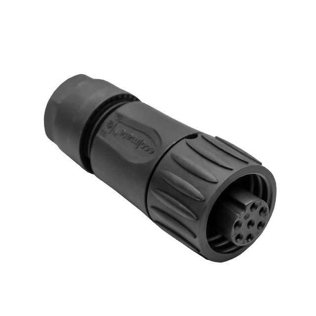
ITT Cannon, LLC生产的MS3101E16S-1SW是一款符合MIL-DTL-5015标准的圆形连接器,属于坚固耐用的工业级电气连接器。该型号广泛应用于对可靠性、稳定性和环境适应性要求较高的场景。

典型应用场景包括航空航天领域,用于飞机内部控制系统、传感器和电源连接;在国防与军事装备中,适用于通信设备、雷达系统及车载电子系统,具备良好的抗振动和耐冲击性能。此外,该连接器也常见于工业自动化设备、重型机械和石油天然气勘探设备中,能在恶劣环境(如高温、潮湿、粉尘)下保持稳定电气连接。

MS3101E16S-1SW为插针式(插头),外壳尺寸为16S,螺纹锁紧结构确保连接牢固,具备优良的电磁屏蔽性能和环境密封性,适合需要高可靠信号或电力传输的场合。其金属外壳设计增强了机械强度和耐用性,适用于固定安装或频繁插拔较少的系统。

总之,该连接器主要应用于航空电子、军用设备、工业控制和能源领域,是高可靠性机电系统中的关键组件。
| 参数 | 数值 |
| 产品目录 | |
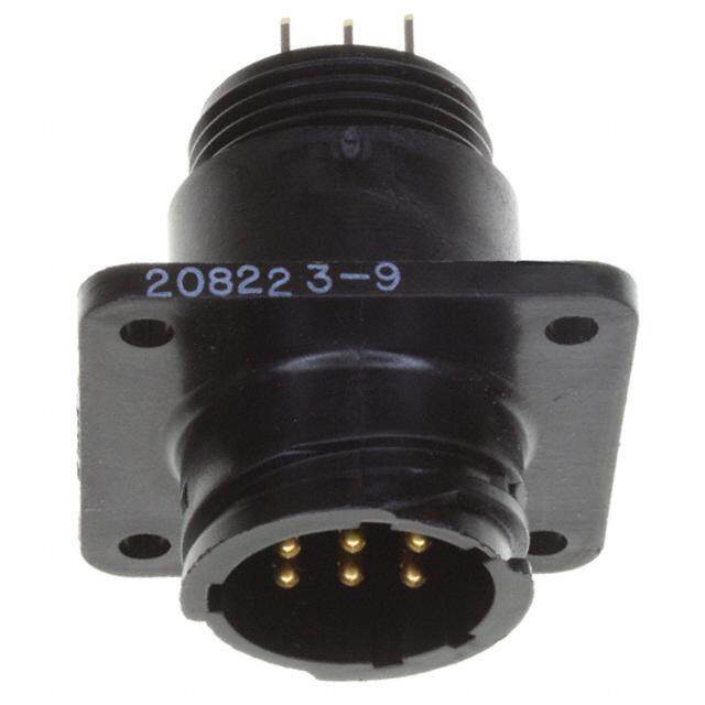
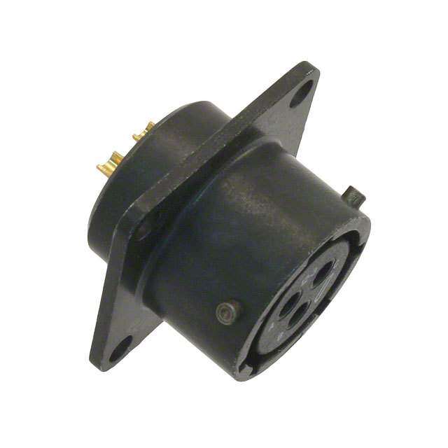
| 描述 | CONN RCPT 7POS INLINE W/SKTS |
| 产品分类 | |
| 品牌 | ITT Cannon |
| 数据手册 | |
| 产品图片 | |
| 产品型号 | MS3101E16S-1SW |
| rohs | 含铅 / 不符合限制有害物质指令(RoHS)规范要求 |
| 产品系列 | 军用, MIL-DTL-5015, MS |
| 侵入防护 | 抗环境影响 |
| 包装 | 散装 |
| 外壳尺寸-插件 | 16S-1 |
| 外壳尺寸,MIL | - |
| 外壳材料,镀层 | 铝合金, 草绿色,镀镉 |
| 安装类型 | 自由悬挂 |
| 工作温度 | -55°C ~ 125°C |
| 朝向 | W |
| 标准包装 | 1 |
| 特性 | 应力消除 |
| 电压-额定 | 500VAC,700VDC |
| 端接 | 焊杯 |
| 紧固类型 | 有螺纹 |
| 触头镀层 | 银 |
| 触头镀层厚度 | - |
| 连接器类型 | 插座,母形插口 |
| 针脚数 | 7 |
| 额定电流 | 22A |

.jpg)
.jpg)


- 商务部:美国ITC正式对集成电路等产品启动337调查
- 曝三星4nm工艺存在良率问题 高通将骁龙8 Gen1或转产台积电
- 太阳诱电将投资9.5亿元在常州建新厂生产MLCC 预计2023年完工
- 英特尔发布欧洲新工厂建设计划 深化IDM 2.0 战略
- 台积电先进制程称霸业界 有大客户加持明年业绩稳了
- 达到5530亿美元!SIA预计今年全球半导体销售额将创下新高
- 英特尔拟将自动驾驶子公司Mobileye上市 估值或超500亿美元
- 三星加码芯片和SET,合并消费电子和移动部门,撤换高东真等 CEO
- 三星电子宣布重大人事变动 还合并消费电子和移动部门
- 海关总署:前11个月进口集成电路产品价值2.52万亿元 增长14.8%

.jpg)

PDF Datasheet 数据手册内容提取
MS C O N N E C T O R S according to MIL-C-5015 MS-6/0100
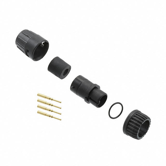
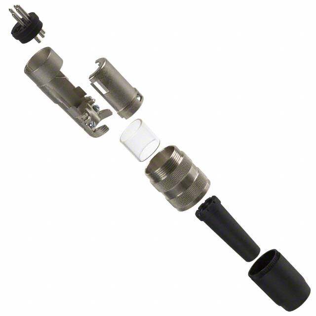
MS Contents Introduction Different Classes General Information ........................................ 2 This catalogue describes Cannon connectors Connector classes MS 3106F, MS 3106R and Shell Styles .................................................... 3 designed and manufactured to MIL-C-5015, the MS 3108R feature an O-ring under the coupling Technical Data ................................................ 4 military specification covering MS electrical nut. It is missing on connectors class MS 3106E Part number Explanation ................................ 5 connectors. These connectors were originally and MS 3108E. Contact Arrangements .................................... 6 designed for aircraft, but are now widely used in Wall Mounting Receptacle .............................. 17 many other fields. They are particularly suitable To reduce size and weight, connector classes Cable Connecting Plug ....................................18 for commercial applications requiring low cost MS 3100R, MS 3101R and MS 3106R have no Box Mounting Receptacle ............................... 19 and high reliability. cable strain relief. The 90° angle plug MS 3106R Straight Plug ................................................... 19 has no cable clamp and is suitable for hose 90° Angle Plug .............................................. 20 The design of connector classes MS-E, MS-F and connection. Strain relief for this connector has Straight Plug, CA-F Type ............................... 21 MS-R conforms to MIL-C-5015 D. The new class to be ordered separately (see page 23). More- Straight Plug, CA-E Type ............................... 22 F connectors supersede the previous class E over, construction and materials used are identi- Through-Bulkhead ......................................... 22 connectors. For new programs only class F cal for all connector classes. Accessories ................................................... 23 should be ordered.The coupling measurements Contacts ....................................................... 27 as well as the dimensions of class MS-E, -F and Different Designations Tooling ........................................................... 29 -R are in accordance with the latest revision of Product Safety Information ........................... 30 VG 0095342. Wall mount receptacle, box re- Connectors with MS designation conform to ceptacle, cable connector and straight plug have MIL-C-5015 in respect of dimensions and con- the same coupling dimensions. This allows tact arrangements. mating of the different classes of these connec- tors. Deviations from this specification, e. g. crimp contacts, other shell or contact finishes, are The connectors of class E, F and R are designed designated CA. to operate in extreme environmental conditions. These connectors are completely sealed to withstand moisture, condensation, vibration and flash-over. MS-F and MS-R connectors have a resilient grommet around each wire. This allows the wires to slide through the grommet with a minimum of friction. Yet when the ferrule is sealed and the endbells are tightened, it provides perfect wire seal through a wide variety of wire diameters. This seal at the rear plus the interfacial seal at the front, effect a completely environmen- tal resistant assembly when the plug is mated to an F or R receptacle. Design Features Straight Plug (E- and F-Types) O Ring MS-F only Straight Plug (R-Type) Bushing Endbell Ferrule Grommet Pin contacts Insulator Coupling Nut Barrel O Ring Dimensions are mm 2 Subject to changes
MS Shell styles and designations Wall mounting receptacles MS 3100E and F / CA 3100E Straight plug MS 3106E and F / CA 3106E and CA06R Dimensions / sizes Page 17 Dimensions / sizes Page 19 Wall mouting receptacle MS 3100R / CA 3100R Straight plug MS 3106R / CA 3106R Dimensions / sizes Page 17 Dimensions / sizes Page 20 Cable connecting plug MS 3101E and F / CA 3101E Dimensions / sizes Page 18 90° Angle plug MS 3108E and R / CA 3108E / R (MS3108R, CA3108F/R without cable clamp) Dimensions / sizes Page 20 Cable connecting plug MS 3101R / CA 3101R Dimensions / sizes Page 18 Straight plug CA 3106F Dimensions / sizes Page 21 Accessories: Cable clamps, Telescoping bushings, Box mounting receptacle MS 3102E and R / CA 3102E Sealing gaskets, Protective caps with and without chain, Dimensions / sizes Page 19 Dummy receptacles, etc. Pages 23 – 26 3
MS Standard Data Shell Material Aluminum alloy Finish Olive drab chromate coating over cadmium plating Insulator Material Polychloroprene (resilient) acc. to MI-R-3065 Contacts Material Copper alloy or brass Finish Silver plated, solder pot tinned Termination Crimp or solder for AWG and metric contact size Operating Temperature –55/125°C Separation Force (N) Contact sizes AWG – 16S/16 12 8 4 0 Metric 10 15S/15 25 100 160 500 Separation force N min. 0,3 1,0 1,5 3 4 8,5 Please note: Connector classes 00E / F, 01E / F, 06E / F and 08E are always delivered with cable bushing. Dimensions of cable bushing see page 22. Electrical Data Operating voltage and connector usage When the connectors in this catalogue are used for voltages greater than 50 Volts and have touchable conductive shell parts they must be used in accordance with the safety regulations DIN VDE Part 410; IEC 60364-4-41. This regulation basically dictates that the power source should be turned off before any mating and unmating of the connector, this regulation does not provide for protection against electrical shock when mating and unmating the connectors in the live condition. Nominal current and potential drop Maximum current ratings of contacts and maximum allowable voltage drop under test conditions when assembled as in service are shown below. Contact size AWG 16S/16 12 8 4 0 Contact size metric 15S/15 25 100 160 500 Wire size mm2 1,0/1,5 2,5 10 16 50 Current rating A* 22 41 73 135 245 Potential drop mV 6 3 1 0,3 0,2 *measured between the contacts at +25-3 °C Service rating MS connectors show no evidence of breakdown when the test voltage given below is applied between the two closest contacts and between the shell and the contacts closest to the shell for a period of one minute. High potential test voltage is conducted in VG 95319 part 2 test no. 5.13 and VG 95210 part 31. MS Service rating Instruments A D E Test voltage Veff 50 Hz 1050 1600 2500 3000 Air spacing mm 0,7 1,1 2,8 4,8 Creeping distance mm 0,7 1,1 2,8 4,8 Dimensions are mm 4 Subject to changes
MS Part Number Explanation MS 3106 R 18-1 P W * CA 3106 F 18-1 S - F80* Prefix MS – conform to MIL-C-5015 CA – Cannon designation for any modification Shell style (see pages 17 – 22) 3100 – wall mounting receptacle 3101 – cable connecting plug 3102 – box mounting receptacle 3106 – straight plug 3108 – 90° plug Class E –with resilient insulator and integral clamp for cable strain relief F – same as E, however style 3106 with O-ring seal under the coupling nut R –with resilient insulator and shortened, lightweight endbell (additional sealing with O-ring under the coupling nut for shell styles 3106 and 3108) Shell size 10S, 12S, 12, 14S, 14, 16S, 16, 18, 20, 22, 24, 28, 32 and 36 Contact arrangements See pages 6 through 16 Contact type P – pin S – socket Alternate insert position Modifications A176–Contacts hard gold over nickel F 80 –Snap-in crimp contacts for AWG size conductors F183 –Snap-in crimp contacts for metric conductors (Crimp contacts are to be ordered separately and will be supplied as loose pieces. After wiring they are inserted into the insulator by the customer) 5
MS Wire Selection The connectors are designed for individual used. When using wires which do not cor- wiring. Spray water and moisture resistance are respond to these specifications the wire dia- only guaranteed if wires according to MIL-W- meters and outer dimensions of the insulation 5086, LN 9251 (for AWG diameters), TL 6145- indicated in below table have to be adhered to. 009 and TL 6145-011 (for metric diameters) are Contact size Conductor size Insulation sizes for solder contacts for crimp contacts (in mm) for AWG mm2 AWG conductor ∅ metric conductor ∅ AWG metric mm mm2 mm contacts contacts – / 10 – – – – 0,75 1,0 1,0 - 1,4 – 2,0 - 2,5 16S/15S 16-22 1,2 - 0,4 16 1,25 - 1,7 1,0 - 1,7 1,25 - 1,7 1,63 - 3,3 2,2 - 2,8 16 / 15 16-22 1,2 - 0,4 16 1,25 - 1,7 1,0 - 1,5 1,25 - 1,7 1,63 - 3,3 2,2 - 2,8 12 / 15 12-14 3,5 - 2,0 12 1,95 - 2,2 2,5 1,95 - 2,2 2,9 - 4,3 3,1 - 3,5 8 / 100 8 - 10 8,5 - 4,5 8 4,0 - 4,5 10 4,3 - 4,8 2,9 - 6,4 5,9 - 6,5 4 / 160 4 - 6 21,5 - 13,5 4 6,0 - 6,9 16 5,2 - 6,0 7,0 - 9,4 7,1 - 7,7 0 / 500 0 - 2 53,0 - 33,5 0 10,6 - 11,5 50 9,6 - 10,7 10,6 - 14,0 12,1 - 12,8 Contact Arrangements In the table on pages 7 – 14 the contact arran- Alternate Insert Positions gements are listed by shell sizes. The shell size Alternate insert positions can be offered to prevent and the contact arrangement number are given mismating of adjacent identic connectors. in the designation printed in bold typefaces: the digits following the dash are the contact arran- The standard insert position is without designa- gement number (see Part Number Explanation tion. The four alternate positions are designated on page 5). W, X, Y and Z (see diagram below). Furthermore, the number of contacts and the Please note: AWG wire sizes are included in the table. The All MS qualified insert positions are listed on recommended wire sizes are shown on this page, pages 7 – 14. Other positions than normal are the electrical data on page 4. not available from stock. Pin insert front view Dimensions are mm 6 Subject to changes
MS Contact Arrangements No. of Contact Service Insulator position – see diagram on page 6 Insulator weight (g) contacts arrangement rating W X Y Z including contacts Contact size AWG pin socket 3 10SL-3 (cid:1)(cid:2) A - - - - 6 9 16S 2 10SL-4 A - - - - 4 6 16S 2 12S-3 (cid:1)+ A 70 145 215 290 4 6 16S 1 12-5 (cid:1) D - - - - 12 3 14S-1 A - - - - 6 9 16S 4 14S-2 + Inst. - 120 240 - 7 11 16S 5 14S-5 (cid:1)+ Inst. - 110 - - 9 13 16S 6 14S-6 (cid:1)(cid:2) Inst. - - - - 11 15 16S 3 14S-7 (cid:1)+ A 90 180 270 - 6 9 16S (cid:1) MIL-C-5015 contact arrangement (cid:2) VG95234 contact arrangement + MS polarization 7
MS Contact Arrangements Contact Arrangements No. of Contact Service Insulator position – see diagram on page 6 Insulator weight (g) contacts arrangement rating W X Y Z including contacts Contact size AWG pin socket 2 14S-9 + INST 70 145 215 290 5 18 16S 7 16S-1 (cid:1)(cid:2)+ A 80 - - 280 14 19 16S 5 16S-8 (cid:1)+ A - 170 265 - 10 15 16S 3 16-7 + A 80 110 250 280 16 25 2 16 (A, B) 1 8 (C) 4 16-9 (cid:1)+ A 35 110 250 325 13 20 2 16 (B,D) 2 12 (A,C) 3 16-10 (cid:1)(cid:2) A 90 180 270 - 17 24 12 2 16-11 (cid:1)+ A 35 110 250 325 11 17 12 1 16-12 A 0 - - - 24 28 4 10 18-1 (cid:2)+ A (B, C, F, G) 70 145 - 290 24 37 16 INST (all other) 2 18-3 + D - - - - 13 22 12 4 18-4 (cid:1)+ D 35 110 250 325 19 30 16 (cid:1) MIL-C-5015 contact arrangement (cid:2) VG95234 contact arrangement + MS polarization Dimensions are mm 8 Subject to changes
MS Contact Arrangements Contact Arrangements No. of Contact Service Insulator position – see diagram on page 6 Insulator weight (g) contacts arrangement rating W X Y Z including contacts Contact size AWG pin socket 3 18-5 (cid:1)+ D 80 110 250 280 15 25 1 16 (A) 2 12 (B,C) 8 18-8 (cid:1)+ A 70 - - 290 18 30 7 16 (A-G) 1 12 (H) 7 18-9 (cid:1)+ INST 80 110 250 280 18 30 5 16 (B,C,E-G) 2 12 (A,D) 4 18-10 + A - 120 240 - 13 22 12 5 18-11 (cid:1)+ A - 170 265 - 31 40 12 6 18-12 + A 80 - - 280 15 25 16 4 18-13 (cid:1)+ A 80 110 250 280 15 24 3 12 (B,C) 1 8 (A) 1 20-2 (cid:1)(cid:2) D - - - - 46 55 0 4 20-4 (cid:1)+ D 45 110 250 - 24 40 12 8 20-7 (cid:1)+ A (C-F) 80 110 250 280 28 42 16 D (A;B;G;H) 6 20-8 (cid:1) INST 80 110 250 280 37 49 4 16 (B;C;E;F) 2 8 (A;D) 9 20A9 (cid:1) D (J) - - - - 21 35 12 A (all other) (cid:1) MIL-C-5015 contact arrangement (cid:2) VG95234 contact arrangement + MS polarization 9
MS Contact Arrangements No. of Contact Service Insulator position – see diagram on page 6 Insulator weight (g) contacts arrangement rating W X Y Z including contacts Contact size AWG pin socket 19 20A48 (cid:2) INST - 80 280 - 30 50 16 7 20-15 + A 80 - - 280 27 46 12 9 20-16 (cid:1)+ A 80 110 250 280 19 32 7 16 (A-G) 2 12 (H;I) 6 20-17 (cid:1)+ A 90 180 270 - 20 33 1 16 5 12 3 20-19 + A 90 180 270 - 33 46 8 4 20-24 (cid:1)+ A 35 110 250 325 40 53 2 16 (A;C) 2 8 (B;D) 14 20-27 (cid:1)+ A 35 110 250 325 26 42 16 17 20-29 (cid:1)+ A 80 - - 280 29 47 16 11 20-33 (cid:1) A - - - - 23 38 16 3 22-2 (cid:1)(cid:2)+ D 70 145 215 290 35 50 8 (cid:1) MIL-C-5015 contact arrangement (cid:2) VG95234 contact arrangement + MS polarization Dimensions are mm 10 Subject to changes
MS Contact Arrangements No. of Contact Service Insulator position – see diagram on page 6 Insulator weight (g) contacts arrangement rating W X Y Z including contacts Contact size AWG pin socket 1 22-7 (cid:1) E 0 - - - 45 57 0 3 22-9 (cid:1)+ E 70 145 215 290 21 32 12 5 22-12 (cid:1)+ D 80 110 250 280 28 42 3 16 (A;C;D) 2 8 (B;E) 19 22-14 (cid:1)+ A 80 - - 280 30 50 16 14 22-19 (cid:1)+ A 80 110 250 280 28 47 16 9 22-20 + A 35 110 250 325 29 41 16 4 22-22 + A - 110 250 - 38 50 8 8 22-23 (cid:1)+ D (H) 35 - 250 - 34 54 12 A (all others) 9 22-27 (cid:1)(cid:2)+ D (J) 80 - 250 280 31 44 8 16 (A-H) A (all others) 1 8 (J) 7 22-28 + A - - - - 38 54 12 (cid:1) MIL-C-5015 contact arrangement (cid:2) VG95234 contact arrangement + MS polarization 11
MS Contact Arrangements No. of Contact Service Insulator position – see diagram on page 6 Insulator weight (g) contacts arrangement rating W X Y Z including contacts Contact size AWG pin socket 7 24-2 (cid:1)+ D 80 - - 280 33 53 12 16 24-7(cid:1)+ A 80 110 250 280 45 65 14 16 (A-M,O) 2 12 (P,N) 7 24-10 (cid:1)(cid:2)+ A 80 - - 280 65 85 8 9 24-11 (cid:1)(cid:2)+ A 35 110 250 325 55 75 6 12 (A-C,G-I) 3 8 (D;F) 5 24-12 (cid:2) A - - - - 60 80 3 12 2 4 12 24-19 A - - - - 28 47 16 11 24-20 (cid:1)+ D 80 110 250 280 40 60 9 16 (A-D,G-L) 2 12 (E;F) 4 24-22 (cid:1)+ D 45 110 250 - 44 61 8 24 24-28 + Inst. 80 110 250 280 40 65 16 (cid:1) MIL-C-5015 contact arrangement (cid:2) VG95234 contact arrangement + MS polarization Dimensions are mm 12 Subject to changes
MS Contact Arrangements No. of Contact Service Insulator position – see diagram on page 6 Insulator weight (g) contacts arrangement rating W X Y Z including contacts Contact size AWG pin socket 22 28-11 + A 80 110 250 280 65 110 18 16 (A-I,N-X) 4 12 (J-M) 26 28-12 (cid:1)+ A 90 180 270 - 47 77 16 35 28-15 + A 80 110 250 280 54 90 16 14 28-20 (cid:1)+ A 80 110 250 280 65 110 4 16 (K-N) 10 12 (A-J,P) 37 28-21 (cid:1)(cid:2)+ A 80 110 250 280 58 93 16 9 28A16 A (e) - 100 260 - 85 135 5 16 (A;D-F;J) INST (all other) 4 4 (B;C;G;H) 28 28A63 (cid:2) - - - - 85 135 9 12 A (e) 19 16 INST (all other) 5 32-1 (cid:1)(cid:2)+ E (A) 80 110 250 280 - - 3 12 (A, C, D) D (all other) 2 0 (B, E) (cid:1) MIL-C-5015 contact arrangement (cid:2) VG95234 contact arrangement + MS polarization 13
MS Contact Arrangements No. of Contact Service Insulator position – see diagram on page 6 Insulator weight (g) contacts arrangement rating W X Y Z including contacts Contact size AWG pin socket 2 32-5 + D 35 110 250 325 86 114 0 23 32-6 (cid:1)(cid:2)+ A 80 110 250 280 130 170 16 16 (A-D;S) 2 12 (U;V) 3 8 (P-T) 1 4 (W;X) 35 32-7 (cid:1)(cid:2)+ INST (A;B;h;i) 80 125 235 280 110 160 28 16 (A-N;W;Z;a;k) A (all other) 7 12 (O-V) 30 32-8 + A 80 125 235 280 105 155 24 16 (A-L;T-Z;a-e) 6 12 (M-S) 4 32-17 (cid:1)+ D 45 110 250 - 101 128 4 61 32A69 (cid:2) INST - 110 250 - 49 84 41 20 20 16 4 36-5 (cid:1)(cid:2)+ A - 120 240 - 152 181 0 48 36-10 (cid:1)(cid:2)+ A 80 125 235 280 79 133 16 (cid:1) MIL-C-5015 contact arrangement (cid:2) VG95234 contact arrangement + MS polarization Dimensions are mm 14 Subject to changes
MS Contact Arrangements Contact No. of Wire size Amp. Service Weight Contact No. of Wire size Amp. Service Weight arrange- contacts AWG mm2 group Polychloroprene arrange- contacts AWG mm2 group Polychloroprene ment insert ment insert lbs. gr. lbs. gr. Shell size 10S/10SL Shell size 18 (continued) 10SL-3 3 16 1,5 22 A P.010 4 18-5 2 12 2,5 41 D P.040 18 S.017 8 1 16 1,5 22 S.059 27 10SL-4 2 16 1,5 22 A P.009 4 18-6 1 4 16,0 13,5 D P.048 22 S.014 6 S. - - Shell size 12/12 18-8 1 12 2,5 41 A P.044 20 7 16 1,5 22 S.062 28 12S-3 2 16 1,5 22 A P.010 5 S.016 7 18-9 2 12 2,5 4 Inst. P.045 20 12-5 1 12 2,5 41 D P.- - 5 16 1,5 22 S.062 28 Shell size 14/14S 18-10 4 12 2,5 41 A P.046 21 S.067 30 14S-1 3 16 1,5 22 A P.- - S.- - 18-11 5 12 2,5 41 A P.049 22 S.071 32 14S-2 4 16 1,5 22 Inst. P.019 9 S.028 13 18-12 6 16 1,5 22 A P.039 18 S.054 24 14S-5 5 16 1,5 22 Inst. P.017 8 S.029 13 18-13 1 8 10,0 73 A P.- - S.- - 14S-6 6 16 1,5 22 Inst. P.031 15 S.015 7 Shell size 20 14S-7 3 16 1,5 22 A P.015 7 20-2 1 0 50 245 D P.092 41 S.024 11 S.101 45 14S-9 2 16 1,5 22 A P.013 6 20-4 4 12 2,5 41 D P.057 26 S.022 10 S.086 38 Shell size 16/16S 20-7 8 16 1,5 22 A (C,D,E,F) P.053 26 16S-1 7 16 1,5 22 A P.025 11 D S.042 19 (A,B.H.G) S.076 34 16-7 1 8 10,0 73 A P.- - 20-15 7 12 2,5 41 A P.068 30 2 16 1,5 22 S.- - S.100 45 16S-8 5 16 1,5 22 A P.023 10 20-16 2 12 2,5 41 A P.059 26 S.039 18 7 16 1,5 22 S.084 38 16S-9 5 16 1,5 22 A P.023 10 20-17 5 12 2,5 41 A P.068 31 S.039 18 1 16 1,5 22 S.098 38 16-9 2 12 2,5 41 A P.031 14 20-19 3 8 10,0 73 A P.068 31 2 16 1,5 22 A S.044 20 S.091 41 16-10 3 12 2,5 41 A P.031 14 20-24 2 8 10,0 73 A P.062 28 S.047 21 2 16 1,5 22 S.085 38 16-11 2 12 2,5 41 A P.028 13 20-27 14 16 1,5 22 A P.062 28 S.042 19 S.082 37 16-12 1 4 16,0 135 A P.031 14 20-29 17 16 1,5 22 A P.065 29 S.047 21 S.085 38 Shell size 18 20-33 11 16 1,5 22 A P.057 25 S.079 35 18-1 10 18 1,5 22 A (B,C,F,G) P.044 20 Inst. 20A9 9 - 2,5 41 D for J P.020 9 (all others) S.058 26 S.033 15 18-3 2 12 2,5 41 D P.038 17 20A48 19 - 1,5 22 Inst. P .020 S.057 26 S.036 16 18-4 4 16 1,5 22 D P.037 17 20-8 4 16 1,5 22 Inst. P.059 26 S.053 24 2 8 10 73 S.080 36 15
MS Contact Arrangements Contact No. of Wire size Amp. Service Weight Contact No. of Wire size Amp. Service Weight arrange- contacts AWG mm2 group Polychloroprene arrange- contacts AWG mm2 group Polychloroprene ment insert ment insert lbs. gr. lbs. gr. Shell size 22 Shell size 28 22-2 3 8 10 73 D P.077 34 28-11 4 12 2,5 41 A P.131 59 S.104 47 18 16 1,5 22 S.182 53 28-12 26 16 1,5 22 A P.127 57 22-7 1 0 50 245 E P.101 - S.172 78 S.- 28-15 35 16 1,5 22 A P.139 63 22-9 3 12 2,5 41 E P.062 28 S.181 82 S.092 42 28-20 10 12 2,5 41 A P.134 80 22-12 2 8 10 73 D P.072 32 4 16 1,5 22 S.196 89 3 16 1,5 22 S.100 45 28-21 37 16 1,5 22 A P.142 64 22-14 19 16 1,5 22 A P.077 34 S.183 83 S.100 45 28A16 4 4 16 135 A P.- - 22-19 14 16 1,5 22 A P.070 31 5 16 1,5 22 S.- - S.095 43 28A63 19 - 1,5 22 A P.042 19 22-20 9 16 1,5 22 A P.063 29 9 - 2,5 41 S.077 35 S.090 41 Shell size 32 22-22 4 8 10 73 A P.085 38 S.112 50 32-1 2 0 50 245 E (A) P.- - 3 12 2,5 41 D 22-23 8 12 2,5 41 D (H) P.080 36 (all others) S.- - A (all others) S.118 53 32-5 2 0 50 245 D P.- - S.- - 22-27 1 8 10 73 A (H) P.070 31 8 16 2,5 22 D (J) S.097 44 32-6 2 4 16 135 A P.-223 101 3 8 10 73 S.287 130 22-28 7 12 2,5 41 A P.086 38 2 12 2,5 41 S.120 54 16 16 1,5 22 Shell size 24 32-7 7 12 2,5 41 Inst. (A,B,h,j) P.198 89 24-2 7 12 2,5 41 D P.089 40 28 16 1,5 22 D S.133 60 (all others) S.274 124 24-7 2 12 2,5 41 A P.090 40 32-8 6 12 2,5 41 A P.189 86 14 16 1,5 22 S.125 56 24 16 1,5 22 S.265 120 24-10 7 8 10 73 A P.125 56 32-17 4 4 16 135 D P.223 101 S.157 71 S.283 129 24-11 3 8 10 73 A P.111 50 32A69 41 - 1,0 7,5 Inst. P.119 54 6 12 2,5 41 S.153 69 20 - 1,5 22 S.121 55 24-12 3 12 10 41 A P.027 12 Shell size 36 2 4 16 135 S.051 23 36-5 4 0 50 245 A P.- - 24-19 12 16 1,5 22 A P.- - S.- S.- - 36-10 48 16 1,5 22 A P.214 97 24-20 2 12 2,5 41 D P.083 37 S.321 145 9 16 1,5 22 S.120 54 24-22 4 8 10 73 D P.- - S.132 59 24-28 24 16 1,5 22 Inst. P.096 43 S.126 57 For additional contact arrangements please consult factory. Dimensions are mm 16 Subject to changes
MS Wall Mounting Receptacle MS3100E / CA3100E / MS3100F MS3100E and F are wall mounting recep- tacles which mate with 3106 and 3108 plugs. Note: MS3100E corresponds to MS3100F and is available upon request. For new programs please order MS3100F only. If crimp version is required please order CA3100E...F80 or CA3100E...F183 Order reference A B E1) K L M R S V W T Pin insert* Thread min. max. ±0,7 max. +0,4 ±0,1 ±0,3 max. max. +0,2 / –0,1 MS3100E10SL-**P 5/8-24 EF-2A 9,5 6,5 3,0 60 14,2 18,2 25,4 22,7 27,0 3,1 MS3100E-12S-**P 3/4-20UNEF-2A 9,5 6,5 3,0 60 14,2 20,6 28,0 22,7 27,0 3,1 MS3100E14S-**P 1/8-20UNEF-2A 9,5 9,0 3,0 70 14,2 23,0 30,0 27,5 34,0 3,1 MS3100E16S-**P 1 -20UNEF2A 9,5 11,0 3,0 70 14,2 24,6 32,5 30,0 38,0 3,1 MS3100E12-**P 3/4-20UNEF-2A 15,8 6,5 3,0 70 19,0 20,6 28,0 22,7 27,0 3,1 MS3100E14-**P 7/8-20UNEF-2A 15,8 9,0 3,0 70 19,0 23,0 30,0 27,5 34,0 3,1 MS3100E16-**P 1 -20UNEF-2A 15,8 11,0 3,0 70 19,0 24,6 32,5 30,0 38,0 3,1 MS3100E18-**P 1-1/8-18NEF-2A 15,8 14,2 3,9 77 19,0 27,0 35,0 32,2 40,5 3,1 MS3100E20-**P 1-1/4-18NEF-2A 15,8 15,8 3,9 77 19,0 29,4 38,0 37,5 47,5 3,1 MS3100E22-**P 1-3/8-18NEF-2A 15,8 15,8 3,0 77 19,0 31,8 41,0 37,5 47,5 3,1 MS3100E24-**P 1-1/2-18NEF-2A 15,8 21,4 3,9 77 20,6 34,9 44,5 43,3 54,0 3,7 MS3100E28-**P 1-3/4-18NS-2A 15,8 21,4 3,0 85 20,6 39,7 50,8 43,3 54,0 3,7 MS3100E32-**P 1 -18NS-2A 15,8 26,7 3,9 85 22,2 44,5 57,0 51,7 64,5 4,4 MS3100E36-**P 2-1/4-16UN-2A 15,8 31,7 3,9 105 22,2 49,2 63,5 58,0 73,0 4,4 *For socket inserts substitute S for P **Add contact arrangement number (see pages 7 – 14) 1) maximum cable diameter MS3100R / CA3100R The MS3100R receptacles feature a shorter and lightweight endbell and mate with 3106 and 3108 plugs. If crimp version is required please order CA3100R...F80 or CA3100R...F183 Order reference A B K L M P R S T Pin insert* Thread min. ±0,7 max. +0,4 max. ±0,1 ±0,3 +0,2 / –0,1 MS3100R-10SL-**P 5/8-24NEF-2A 9,5 3,0 45 14,2 24,4 18,2 25,4 3,1 MS3100R-12S-**P 3/4-20UNEF-2A 9,5 3,0 45 14,2 24,4 20,6 28,0 3,1 MS3100R14S-**P 7/8-20UNEF-2A 9,5 3,0 55 14,2 29,0 23,0 30,0 3,1 MS3100R16S-**P 1 -20UNEF-2A 9,5 3,0 55 14,2 31,5 24,6 32,5 3,1 MS3100R12-**P 3/4-20UNEF-2A 15,8 3,0 55 19,0 24,4 20,6 28,0 3,1 MS3100R14-**P 7/8-20UNEF-2A 15,8 3,0 55 19,0 29,0 23,0 30,0 3,1 MS3100R16-**P 1 -20UNEF-2A 15,8 3,0 55 19,0 31,5 24,6 32,5 3,1 MS3100R18-**P 1 1/8-18NEF-2A 15,8 3,9 60 19,0 36,6 27,0 35,0 3,1 MS3100R20-**P 1-1/4-18NEF-2A 15,8 3,9 60 19,0 39,7 29,4 38,0 3,1 MS3100R22-**P 1-3/8-18NEF-2A 15,8 3,9 60 19,0 39,7 31,8 41,0 3,1 MS3100R24-**P 1-1/2-18NEF-2A 15,8 3,9 60 20,6 47,4 34,9 44,5 3,7 MS3100R26-**P 1-3/4-18 S-2A 15,8 3,9 67 20,6 47,4 39,7 50,8 3,7 MS3100R32-**P 2 -18NS-2A 15,8 3,9 67 22,2 55,9 44,5 57,0 4,4 MS3100R36-**P 2-1/4-16UN-2A 15,8 3,9 85 22,2 60,8 49,2 63,5 4,4 *For socket inserts substitute S for P **Add contact arrangement number (see pages 7 – 14) 17
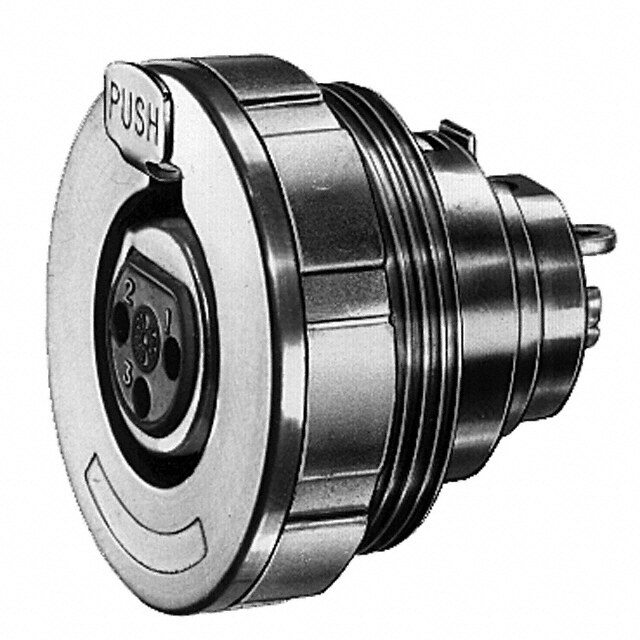
MS Cable Connecting Plug MS3101E/CA3101E MS3101F MS3101E and F are cable connecting plugs without flange and coupling nut. MS3101E and F mate with 3106 and 3108 plugs. For new programs order MS3101F only. If crimp version is required please order CA3101E...F80 or CA3101E...183 Order reference A B E 1) G K L M S V W Pin insert* Thread min. max. max. ±0,7 max. +0,4 max. max. max. MS3101E10SL-**P 5/8-2ENEF-2A 9,5 6,5 21,8 3,0 60 14,2 16,2 22,7 27,6 MS3101E12S-**P 3/4-20UNEF-2A 9,5 6,5 25,0 3,0 60 14,2 19,3 22,7 27,0 MS3101E14S-**P 7/8-20UNEF-2A 9,5 9,0 28,2 3,0 70 14,2 22,5 27,5 34,0 MS3101E16S-**P 1 -20U EF-2A 9,5 11,0 31,4 3,0 70 14,2 25,6 30,0 38,0 MS3101E12-**P 3/4-20UNEF-2A 15,8 6,5 25,0 3,0 70 19,0 19,3 22,7 27,0 MS3101E14-**P 7/8-20UNEF-2A 15,8 9,0 28,2 3,0 70 19,0 22,5 27,5 34,0 MS3101E16-**P 1 -20UNEF-2A 15,8 11,0 31,4 3,0 70 19,0 25,6 30,0 38,0 MS3101E18-**P 1-1/8-18NEF-2A 15,8 14,2 34,5 3,9 77 19,0 28,8 32,2 40,5 MS3101E20-**P 1-1/4-18NEF-2A 15,8 15,8 37,6 3,9 77 19,0 32,0 37,5 47,5 MS3101E22-**P 1-3/8-18NEF-2A 15,8 15,8 41,0 3,9 77 19,0 35,2 37,5 47,5 MS3101E24-**P 1-1/2-18NEF-2A 15,9 21,4 43,8 3,9 77 20,6 38,4 43,3 54,0 MS3101E28-**P 1-3/4-18NS-2A 15,8 21,4 50,5 3,9 85 20,6 44,8 43,3 54,0 MS3101E32-**P 2 -18NS-2A 15,8 26,7 57,0 3,9 85 22,2 51,2 51,7 64,5 MS3101E36-**P 2-1/4-16UN-2A 15,8 31,7 63,2 3,9 105 22,2 57,5 58,0 72,0 *For socket inserts substitute S for P **Add contact arrangement number (see pages 7 – 14) 1) maximum cable diameter MS3101R / CA3101R MS3101 cable connecting plugs without coupling nut feature a shorter and light- weight endbell than MS3101E and mate with 3106 and 3108 plugs. If crimp version is required please order CA3101R..F80 or CA3101R...F183 Order reference A B G K L M P S Pin insert* Thread min. max. ±0,7 max. +0,4 max. max MS3101R10SL-**P 5/8-24NEF-2A 9,5 21,8 3,0 45 14,2 24,4 16,2 MS3101R12S-**P 3/4-20UNEF-2A 9,5 25,0 3,0 45 14,2 24,4 19,9 MS3101R14S-**P 7/8-20UNEF-2A 9,5 28,2 3,0 55 14,2 29,0 22,5 MS3101R16S-**P 1 -20UNEF-2A 9,5 31,4 3,0 55 14,1 31,5 25,6 MS3101R12-**P 3/4-0UNEF-2A 15,8 25,0 3,0 55 19,0 24,4 19,3 MS3101R14-**P 7/8-20UNEF-2A 15,8 28,2 3,0 55 19,0 29,0 22,5 MS3101R16-**P 1 -20UNEF-2A 15,8 31,4 3,0 55 19,0 31,5 25,6 MS3101R18-**P 1-1/8-18NEF-2A 15,8 34,5 3,9 60 19,0 36,6 28,8 MS3101R20-**P 1-1/4-18NEF-2A 15,8 37,6 3,9 60 19,0 39,7 32,0 MS3101R22-**P 1-3/8-18 EF-2A 15,8 41,0 3,0 60 19,0 39,7 35,2 MS3101R24-*P 1-1/2-18NEF-2A 15,8 43,8 3,9 60 20,6 47,4 38,4 MS3101R28.**P 1-3/4-18NS-2A 15,8 50,5 3,9 67 20,6 47,4 44,8 MS3101R32-**P 2 -18NS-2A 15,8 57,0 3,9 67 22,2 55,9 51,2 MS3101R36-**P 2-1/4-16UN-2A 15,8 63,2 3,9 85 22,2 60,8 57,5 *For socket inserts substitute S for P **Add contact arrangement number (see pages 7 – 14) Dimensions are mm 18 Subject to changes
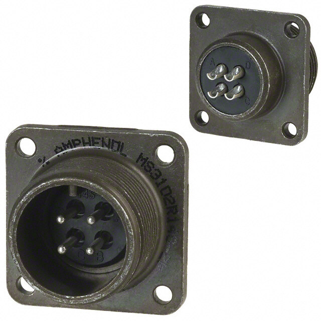
MS Box Mounting Receptacle / Straight Plug MS3102E MS3102R CA3102E Note: For new programs order MS3102R only. If crimp version is required please order CA3102R...F80 or CA3102R...F183. MS3102E and R are box mounting receptacles with square flange and mate with 3106 and 3108 plugs. Dimension X max for pin or socket (solder contacts only) Shell size Contact size 16 12 8 4 0 10SL 13,6 - - - - 12S, 14S,16S 13,2 - - - - 12 17,9 17,9 - - - 14 17,9 17,9 19,5 - - 16 17,9 17,9 19,5 19,5 - 18 17,1 17,1 18,7 18,7 - 20, 22 17,1 17,1 18,7 18,7 24,7 24, 28 15,5 15,5 17,1 17,1 23,1 32, 36 13,9 13,9 15,5 15,5 21,5 Order reference A B K L M P R S T Pin insert* Thread min. ±0,7 max. +0,4 max. ±0,1 ±0,3 +0,2 / –0,2 MS3102R10SL-**P 5/8-24NEF-2A 9,5 3,0 25,1 14,2 15,9 18,2 25,4 3,1 MS3102R12S-**P 3/4-20UNEF-2A 9,5 3,0 25,1 14,2 15,9 20,6 28,0 3,1 MS3102R14S-**P 7/8-20UNEF-2A 9,5 3,0 25,1 14,2 19,0 23,0 30,0 3,1 MS3102R16S-**P 1 -20U EF-2A 9,5 3,0 25,1 14,2 22,2 24,6 32,5 3,1 MS3102R16S-**P 1 -20UNEF-2A 9,5 3,0 25,1 14,2 22,2 24,6 32,5 3,1 MS3102R12-**P 3/4-20UNEF-2A 15,8 3,0 34,6 19,0 15,9 20,6 28,0 3,1 MS3102R14-**P 7/8-20UNEF-2A 15,8 3,0 34,6 19,0 19,0 23,0 30,0 3,1 MS3102R16-**P 1 -20UNEF2A 15,8 3,0 34,6 19,0 22,2 24,6 32,5 3,1 MS3102R18-**P 1-1/8-18NEF-2A 15,8 3,9 34,6 19,0 25,4 27,0 35,0 3,1 MS3102R20-**P 1-1/4-18NEF-2A 15,8 3,9 34,6 19,0 29,0 29,4 38.0 3,1 MS3102R22-**P 1-3/8-18NEF-2A 15,8 3,9 34,6 19,0 32,2 31,8 41,0 3,1 MS3102R24-**P 1-1/2-18NEF-2A 15,8 3,9 36,2 20,6 35,3 34,9 44,5 3,7 MS3102R28-**P 1-3/4-18NS-2A 15,8 3,9 36,2 20,6 41,2 39,7 50,8 3,7 MS3102R32-**P 2 -18NS-2A 15,8 3,9 37,8 22,2 47,6 44,5 57,0 4,4 MS3102R36-**P 2-1/4-16UN-2A 15,8 3,9 37,8 22,2 52,4 49,2 63,5 4,4 *For socket inserts substitute S for P **Add contact arrangement number (see pages 7 – 14) MS3106E / CA3106E If crimp version is required please order CA3106E...F80 (without O ring), CA3106E...F183 (without O ring) or CA06R...F183 (with O ring). MS3106F / CA06R MS3106E and F are straight plugs. They mate with 3100 and 3102 receptacles and 3101 plugs. Note: MS3106E corresponds to MS3106F, how- ever, MS3106F has an O ring seal. For new programs order MS3101F only. Order reference A E 1) L P V W Pin insert* Thread max. max. max. max. max. MS3106E10SL-**P 5/8-24NEF-2B 6,5 55,0 24,1 22,7 27,0 MS3106E12S-**P 3/4-20UNEF-2B 6,5 55,0 25,8 22,7 27,0 MS3106E14S-**P 7/8-20UNEF-2B 9,0 60,0 28,8 27,5 34,0 MS3106E16-**P 1 -20UNEF-2B 11,0 60,0 31,8 30,0 38,0 MS3106E12-**P 3/4-20UNEF-2B 6,5 70,0 25,6 22,7 27,0 MS3106E14-**P 7/8-20UNEF-2B 9,0 70,0 28,8 27,5 34,0 MS3106E16-**P 1 -20UNEF-2B 11,0 70,0 31,8 30,0 38,8 MS3106E18-**P 1-1/8-18NEF-2B 14,2 75,0 34,1 32,2 40,5 MS3106E20-**P 1-1/4-18NEF-2B 15,8 75,0 37,4 37,5 47,5 MS3106E22-**P 1-3/8-18NEF-2B 15,8 75,0 40,5 37,5 47,0 MS3106E24-**P 1-1/2-18NEF-2B 21,4 75,0 43,8 43,3 54,0 MS3106E28-**P 1-3/4-18NS-2B 21,4 90,0 50,2 43,3 73,0 MS3106E32-**P 2 -18NS-2B 26,7 90,0 56,4 51,7 64,5 MS3106E36-**P 2-1/4-16UN-2B 31,7 100,0 62,8 58,0 73,0 *For socket inserts substitute S for P **Add contact arrangement number (see pages 7 – 14) 1) maximum cable diameter 19
MS Straight Plug / 90° Plug MS3106R / CA3106R The MS3106R straight plug has a shorter lightweight endbell than MS3106E and F. It contains an O ring seal under the coupling nut. MS3106R plugs mate with 3100 and 3102 receptacles and 3101 plugs. If crimp version is required please order CA3106R...F80 or CA3106R...183 Order reference A L M P Pin insert* Thread max. max. max. MS3106R10SL-**P 5/8-24NEF-2B 40,0 24,4 24,1 MS3106R12S-**P 3/4-20UNEF-2B 40,0 24,4 25,8 MS3106R14S-**P 7/8-20UNEF-2B 45,0 29.0 28,8 MS3106R16S-**R 1 -20UNEF-2B 45,0 31,5 31,8 MS3106R12-**P 3/4-20U EF-2B 55,0 24,4 25,8 MS3106R14-**P 7/820UNEF2B 55,0 29,0 28,8 MS3106R16-**P 1 -20UNEF-2B 55,0 31,5 31,8 MS3106R18-**P 1-1/8-18NEF-2B 60,0 36,5 34,1 MS3106R20-**P 1-1/4-18 EF-2B 60,0 39,7 37,4 MS3106R22-**P 1-3/8-18NEF-2B 60,0 39,7 40,5 MS3106R24-**P 1-1/2-18 EF-28 60,0 47,4 43,6 MS3106R28-**P 1-3/4-18NS-2B 70,0 47,4 50,2 MS3106R32-**P 2 -18NS-2B 70,0 55,9 56,4 MS3106R36-**P 2-1/4-16UN-2B 90,0 60,8 62,8 *For socket inserts substitute S for P **Add contact arrangement number (see pages 7 – 14) MS3108E / CA3108E If crimp version is required please order CA3108E...F80 (without O ring), CA3108E...F183 (without O ring) or CA3108R...F80 (with O ring), MS3108R / CA3108R CA3108R...F183 (with O ring) MS3108R 90° right angle plugs mate with 3100 and 3102 receptacles and 3101 plugs. The 3108R has an O ring seal under the coupling nut. If no O ring is required the order reference is MS3108E. Note: MS3108R is without cable clamp. If it is required with cable clamp please order the clamp separately. Order reference A E 1) P R V Y Pin insert* Thread max. max. max. max. max. MS3108R10SL-**P 5/8-25NEF-2B 6,5 24,1 22,7 42,0 45,0 MS3108R12S-**P 3/4-20UNEF-2B 6,5 25,8 22,7 42,0 45,0 MS3108R14S-**P 7/8-20UNEF-2B 9,0 28,8 27,5 42,0 47,0 MS3108R16S-**R 1 -20UNEF-2B 11,0 31,8 30,0 45,0 48,0 MS3108R12-**P 3/4-20UNEF-2B 6,5 25,8 22,7 54,0 54,0 MS3108R14-**P 7/8-20UNEF-2B 9,0 28,8 27,5 35,7 55,0 MS3108R16-**P 1 -20UNEF-2B 11,0 31,8 30,0 45,0 57,0 MS3108R18-**P 1-1/8-18NEF-2B 14,2 34,1 32,2 53,0 58,0 MS3108R20-**P 1-1/4-18NEF-2B 15,8 37,4 37,5 53,0 61,0 MS3108R22-**P 1-3/8-18NEF-2B 15,8 40,5 37,5 53,0 61,0 MS3108R24-**P 1-1/2-18NEF-2B 21,4 43,8 43,3 58,0 66,0 MS3108R28-**P 1-3/4-18NS-2B 21,4 50,2 43,3 58,0 66,0 MS3108R32-**P 2 -18NS-2B 26,7 56,4 51,7 66,0 72,0 MS3108R36-**P 2-1/4-16UN-2B 31,7 62,8 58,0 69,0 75,0 *For socket inserts substitute S for P **Add contact arrangement number (see pages 7 – 14) 1) maximum cable diameter Dimensions are mm 20 Subject to changes
MS Straight Plug - F Type CA3101F CA3101F is a cable connecting plug with threaded endbell. Crimp and solder versions are available (please indicate ...F80 or ...F183). CA3101F mate with 3106 and 3108 shell styles. Order reference A C B G H J K L M S Pin insert* Thread Thread min. max. min. min. ±0,7 max. +0,4 max. CA3101F10SL-**P 5/8-24NEF-2A 5/8-24NEF-2A 9,5 16,2 9,5 8,2 3,0 45,0 14,2 21,8 CA3101F12S-**P 3/4-20UNEF-2A 5/8-24NEF-2A 9,5 19,3 9,5 8,2 3,0 45,0 14,2 25,0 CA3101F14S-**P 7/8-20UNEF-2A 3/4-20UNEF-2A 9,5 22,5 9,5 11,1 3,0 45,0 14,2 28,2 CA3101F16S-**P 1 -20UNEF-2A 7/8-20UNEF-2A 9,5 25,6 9,5 14,3 3,0 45,0 14,2 31,4 CA3101F12-**P 3/4-20UNEF-2A 5/8-24NEF-2A 15,8 19,3 9,5 8,2 3,0 57,0 19,0 25,0 CA3101F14-**P 7/8-20UNEF-2A 3/4-20UNEF-2A 15,8 22,5 9,5 11,1 3,0 57,0 19,0 29,2 CA3101F16-**P 1 -20UNEF-2A 7/8-20UNEF-2A 15,8 25,6 9,5 14,3 3,0 57,0 19,0 31,4 CA3101F18-**P 1-1/8-18 EF-2A 1 -20UNEF-2A 15,8 28,8 9,5 16,7 3,9 57,0 19,0 34,5 CA3101F20-**P 1-1/4-18NEF-2A 1-3/16-18NEF-2A 15,8 32,0 9,5 19,8 3,9 57,0 19,0 37,6 CA3101F22-**P 1-3/8-18NEF-2A 1-3/16-18NEF-2A 15,8 35,2 9,5 19,8 3,9 57,0 19,0 41,0 CA3101F24-**P 1-1/2-18NEF-2A 1-7/16-18NEF-2A 15,8 38,4 9,5 25,4 3,9 57,0 20,6 43,8 CA3101F28-**P 1-3/4-18NS-2A 1-7/16-18NEF-2A 15,8 44,8 9,5 27,0 3,9 62,0 20,6 50,5 CA3101F32-**P 2 -18NS-2A 1-3/4-18NS-2A 15,8 51,2 11,0 32,5 3,9 62,0 22,2 57,9 CA3101F36-**P 2-1/4-16UN-2A 2 -18NS-2A 15,8 57,5 11,8 35,7 3,9 62,0 22,2 53,2 *For socket inserts substitute S for P **Add contact arrangement number (see pages 7 – 14) CA3106F CA3106F is a straight plug with external thread, however, without cable clamp and O ring seal. Crimp and solder versions are available (please indicate ...F80 or ...F183). CA3106F mate with 3100, 3101 and 3102 shell styles. Order reference A C E F H J Pin insert* Thread Thread max. max. min. min. CA3106F10SL-**P 5/8-243 EF-2B 5/8-24 EF-2A 50,0 24,1 9,5 8,2 CA3106F12S-**P 3/4-20UNEF-2B 5/8-24NEF2A 50,0 25,8 9,5 8,2 CA3106lF14S-**P 7/8-20UNEF-2B 3/4-20UNEF 50,0 28,8 9,5 11,1 CA3106F16S-**P 1 -20UNEF-2B 7/8-20UNEF-2A 50,0 31,8 9,5 14,3 CA3106F12-**P 3/4-20UNEF-2B 5/8-24NEF-2A 60,0 25,8 9,5 8,2 CA3106F14-**P 7/8-20UNEF-2B 3/4-20UNEF-2A 60,0 28,8 9,5 11,1 CA3106F16-**P 1 -20UNEF-2B 7/8-20UNEF-2A 60,0 31,8 9,5 14,3 CA3106F18-**P 1-1/8-18NEF2B 1 -20UNEF-2A 60,0 34,1 9,5 16,7 CA3106F20-**P 1-1/4-18NEF-2B 1-3/16-18NEF-2A 60,0 37,4 9,5 19,8 CA3106F22-**P 1-3/8-18NEF-2B 1-3/16-18NEF-2A 60,0 40,5 9,5 19,8 CA31.06F24-**P 1-1/2-18NEF-2B 1-7/16-18NEF-2A 65,0 43,8 9,5 25,4 CA3106F28-**P 1-3/4-18NS-2B 1-7/16-18NEF-2A 65,0 50,2 9,5 27,0 CA3106F32-**P 2 -18NS-2B 1-3/4-18NS-2A 65,0 56,4 11,0 32,5 CA3106F36-**P 2-1/4-16UN-2B 2 -18NS-2A 80,0 62,8 11,8 35,7 *For socket inserts substitute S for P **Add contact arrangement number (see pages 7 – 14) 21
MS Straight Plug with Shrink Boot Adapter / Through-Bulkhead CA3106E-DN CA3106E-DN is a straight plug with endbell for shrink boot adapters. Crimp and solder versions are available (please indicate ...F80 or ...F183). CA3106-DN mate with 3100, 3101 and 3102 shell styles. Order reference A B C D E F L P Pin insert* Thread min. max. ±0,2 ±0,2 ±0,5 max. max. CA3106E10SL--**-P-DN 5/8-24NEF-2B 7,7 13,2 15,5 17,0 11,7 11,7 50,0 CA3105E12S-**-P-DN 3/4-20UNEF-2B 7,9 13,2 15,5 17,8 11.8 5ß.ß 25,6 CA3106E14S-**-P-DN 7/8-20UNEF-2B 10,6 17,0 19,1 19,1 11,7 50,0 28,6 CA3106E16S-**-P-DN 1 -20UNEF-2B 13,5 21,9 23,9 23,9 11,5 50,0 31,8 CA3106E12-**-P-DN 3/4-20UNEF-2B 7,9 13,2 15,5 17,8 11,7 50,0 25,6 CA3106E14-**-P-DN 7/8-20UNEF-2B 10,6 17,0 19,1 20,1 11,7 60,0 28,6 CA3106E16-**-P-DN 1 -20UNEF-2B 13,5 21,9 23,9 23,5 11,5 60,0 31,8 CA3106E18-**-P-DN 1-1/8-18NEF-2B 14,6 21,9 23,9 26,5 12,7 60,0 34,1 CA3106E20-**-P-DN 1-1/4-18NEF-2B 18,5 26,6 29,6 30,2 12,7 65,0 37,3 CA3106E22-**-P-DN 1-3/8-18NEF-2B 20,8 26,2 29,6 33,6 12,7 65,0 40,5 CA3106E24-**-P-DN 1-1/2-16NEF-2B 24,6 34,5 37,8 36,1 12,7 65,0 43,8 CA3106E28-**-P-DN 1-3/4-18NS-2B 27,0 34,5 37,8 41,4 12,7 65,0 50,0 CA3106E32-**-P-DN 2 -18NS-2B 33,3 43,6 47,8 48,6 15,2 70,0 56,3 CA3106E36-**-P-DN 2-1/4-16UN-2B 38,5 43,6 47,8 54,8 15,2 80,0 62,7 *For socket inserts substitute S for P **Add contact arrangement number (see pages 7 – 14) TBF TBF is a through-bulkhead which mates with 3106 and 3108 plugs. Order reference A B L M R S T Pin / Socket insert Thread min. max. +0,4 ±0,1 ±0,3 +0,2 / –0,1 TBF10SL-**PS 5/8-24NEF-2A 9,5 40,1 14,2 18,2 25,4 3,1 TBF12S-**PS 3/4-20UNEF-2A 9,5 40,1 14,2 20,6 28,0 3,1 TBF14S-**PS 7/8-20UNEF-2A 9,5 40,1 14,2 23,0 30,0 3,1 TBF16S-**PS 1 -20UNEF-2A 9,5 40,1 14,2 24,6 32,5 3,1 TBF12-**PS 3/4-20UNEF-2A 15,8 54,4 19,0 20,6 28,0 3,1 TBF14-**PS 7/8-20UNEF-2A 15,8 54,4 19,0 23,0 30,0 3,1 TBF16-**PS 1 -20UNEF-2A 15,8 54,4 19,0 24,6 32,5 3,1 TBF18-**PS 1-1/8-18NEF-2A 15,8 54,5 19,0 27,0 35,0 3,1 TBF20-**PS 1-1/4-18NEF-2A 15,8 54,5 19,0 29,4 38,0 3,1 TBF22-**PS 1-3/8-18NEF-2A 15,8 54,5 19,0 31,8 41,0 3,1 TBF24-**PS 1-1/2-18NEF-2A 15,8 54,5 20,5 34,9 44,5 3,7 TBF28-**PS 1-3/4-18NS-2A 15,8 54,5 20,6 39,7 50,8 3,7 TBF32-**PS 2 -18NS-2A 15,8 54,5 22,2 44,5 57,0 4,4 TBF36-**PS 2-1/4-16UN-2A 15,8 54,5 22,2 49,2 63,5 4,4 *For socket inserts substitute S for P **Add contact arrangement number (see pages 7 – 14) Dimensions are mm 22 Subject to changes
MS Accessories Cable Clamp with Bushing Cable clamps are available with or without bushing. To order bushings, add “with bus- hing“ to the part number. For example: MS3057-10A with bushing. Order reference Shell size A B E L R Shell weight Thread max. max. max. max. gr MS3057-4A 10S, 12S, 12 5/8-24NEF-2B 10,5 7,9 20,8 22,5 13,2 MS3057-6A 14S, 14 3/4-20UNEF-2B 10,5 11,1 22,4 27,4 18,6 MS3057-8A 16S, 16 7/8-20UNEF-2B 10,5 14,2 24,0 29,8 23,6 MS3057-10A 18 1 -20UNEF-2B 10,5 15,8 24,0 32,2 27,3 MS3057-12A 20, 22 1-3/16-18NEF-2B 10,5 19,0 24,0 37,4 37,2 MS3057-16A 24, 26 1-7/16-18NEF-2B 10,5 23,7 26,4 43,5 56,3 MS3057-20A 32 1-3/4-18NS-2B 12,0 31,8 28,0 51,7 83,9 MS3057-24A 36 2 -18NS-2B 13,7 34,6 29,6 57,8 109,8 Telescoping Bushing Telescoping gland bushings (used with cable clamp MS3057A) keep dirt, oil and moisture out of endbell. Taping or wrapp- ing wires is eliminated since bushing pro- tects wires going through clamp. Combina- tions of bushings may be used to decrease cable entry diameter to improve sealing. Material is polychloroprene (MS). Order reference Shell size C L R S max. max. –0,3 –0,3 812-8552-000 10SL, 12, 12S 10,0 70,4 6,7 8,1 012-8554-000 14, 14S 12,8 67,4 9,2 11,0 012-0218-000 16, 16S 18,9 63,9 11,2 14,2 012-0219-000 18 22,1 60,6 14,4 15,8 012-0220-000 20, 22 27,0 57,4 16,0 18,9 012-8555-000 24, 28 27,0 57,4 16,78 21,3 012-8556-000 24, 28 33,5 54,4 21,6 23,7 012-8557-000 32 33,05 54,4 21,6 26,6 012-8558-000 32 40,5 51,4 26,9 31,6 012-8556-000 36 40,5 51,4 26,9 31,6 012-0223-000 36 47,0 48,4 31,9 34,8 23
MS Accessories Plastic protective caps Material: Polyethylene Colour: Red Order reference MS3100 / 3101 / 3102 MS3106 / 3108 A B C D max. max. ±0,2 max. 025-0460-000 10SL 21,5 17,8 15,2 16,9 025-0477-000 10 SL 20,4 12,5 14,0 15,7 025-0478-000 12S, 12 23,1 14,6 16,8 18,5 025-0462-000 12S, 12 24,7 17,8 18,5 20,2 025-0479-000 14S, 14 26,3 14,6 19,9 21,6 025-0463-000 14S, 14 27,8 17,8 21,6 23,3 025-0480-000 16S, 16 29,5 14,6 23,1 24,8 025-0498-000 16S, 16 31,5 17,8 25,1 26,8 025-0484-000 18 32,8 14,6 25,9 27,8 025-0507-000 18 34,7 17,8 28,2 30,1 025-0467-000 20 35,4 17,8 28,3 30,2 025-0468-000 20 38,1 17,8 31,8 33,4 025-0469-000 22 39,1 14,6 32,6 34,2 025-0486-000 22 41,4 17,8 34,5 36,5 025-0487-000 24 42,3 14,6 35,5 37,4 025-0510-000 24 44,2 17,8 37,8 39,8 025-0488-000 28 48,4 14,6 41,6 43,5 025-0501-000 28 50,4 17,8 43,9 45,9 025-0489-000 32 54,8 14,6 48,0 49,9 025-0502-000 32 57,0 17,8 50,3 52,2 025-0490-000 36 61,3 14,6 54,2 56,3 025-0503-000 36 63,4 17,8 56,6 58,6 Dust caps for mating side of plugs only. Wire hole fillers Where contacts are not used, the contact cavities are to be closed with wire hole filers Contact size Wire size Part number Colour AWG metric AWG - 10 20 225-1000-000 red 16S/16 15S/15 16 225-0017-000 blue 12 25 12 225-0018-000 yellow 8 60/100 8 225-0019-000 white 4 160 4 225-8502-000 green 0 500 0 225-8503-000 black Dimensions are mm 24 Subject to changes
MS Accessories Metal protective caps These externally threaded caps are used to protect 3106 and 3108 plugs. The material is aluminum alloy. The protective caps are furnished with a sash chain. They are also available with or without chain. MS Cannon Cannon Shell A B H F D G Shell weight Order reference Order reference Order reference size Thread min. +0,2 max. max. max. with chain without chain with chain with chain without chain gr. gr. MS25042-10D CA17530-5101 CA19741-10 10SL 5/8-24NEF-2A 7,7 3,9 16,7 16,3 107,0 6,4 3,2 MS25042-12D CA17530-5102 CA19741-12 12S, 12 3/4-20U EF-2A 12,5 3,9 19,8 21,0 120,0 8,7 4,2 MS25042-14D CA17530-5103 CA19741-14 14S, 14 7/8-20UNEF-2A 12,5 4,9 23,0 21,0 120,0 9,2 5,5 MS25042-16D CA17530-5104 CA19741-16 16S, 16 1 -20UNEF-2A 12,5 3,9 26,2 21,0 120,0 10,0 6,0 MS25042-18D CA17530-51005 CA19741-18 18 1-1/8-18NEF-2A 12,5 3,9 21,0 29,4 120,0 13,2 9,2 MS25042-20D CA17530-5106 CA19741-20 20 1-1/4-18NEF-2A 12,5 4,7 32,5 21,0 124,0 15,5 12,0 MS25042-20D CA17530.5106 CA19741-20 20 1-1/4-18NEF-2A 12,5 4,7 32,5 21,0 134,0 15,5 12,0 MS25042-22D CA17530-5107 CA19741-22 22 1-3/8-18NEF-2A 12,5 4,7 35,7 21,0 134,0 16,5 13,3 MS25042-24D CA17530-5108 CA19741-24 24 1-1/2-18NEF-2A 12,5 4,7 38,9 21,0 147,0 19,2 14,5 MS25042-28D CA17530-5109 CA19741-28 28 1-3/4-18NS-2A 12,5 4,7 45,2 21,0 207.0 25,5 21,0 MS24042-32S CA17530-5110 CA19741-32 32 2 -18NS-2A 12,5 5,5 51,6 21,0 207,0 31,0 28,0 MS25042-36D CA17530-5111 CA19741-36 36 2-1/4-16UN-2A 12,5 5,5 57,9 21,0 207,0 36,05 33,0 Metal protective caps These internally threaded caps are used to protect 3100, 3101 and 3102 receptacless. The material is aluminum alloy. The protec- tive caps are furnished with or without a sash chain. MS Cannon Cannon Shell A B C D E Shell weight Order reference Order reference Order reference size Thread max. max. max. +0,2 with chain without chain with chain with chain without chain gr. gr. MS25043-10D CA2209-5101 CA2322-2 10SL 5/8-24NEF-2B 11,7 20,2 107,0 3,9 5,5 4,1 MS25043-12D CA2209-5102 CA2322-3 12S, 12 3/4-20UNEF-2B 11,7 23,4 120,0 3,9 7,7 5,0 MS25043-14D CA2209-5103 CA2322-4 14S, 14 7/8-20UNEF-2B 11,7 26,6 120,0 3,0 8,2 5,5 MS25043-16D CA2209-5104 CA2322-5 16S, 16 1 -20UNEF-2B 11,7 29,8 120,0 3,9 8,7 6,5 MS25043-18D CA2209-5105 CA2322-6 18 1-1/8-18NEF-2B 11,7 32,9 120,0 3,9 9,6 7,7 MS25043-20D CA2209-5106 CA2322-7 20 1-1/4-18NEF-2B 11,7 36,1 134,0 4,7 11,5 9,2 MS25043-22D CA2209-5107 CA2322-8 22 1-3/8-18NEF-2B 11,7 39,4 134,0 4,7 12,7 10,5 MS25043-24D CA2209-5108 CA2322-9 24 1-1/2-18NEF-2B 11,7 42,6 147,0 4,7 14,5 8,2 MS25043-28D CA2209-5109 CA2322-10 28 1-3/4-18NS-2B 13,3 48,9 207,0 4,7 15,0 13,2 MS25043-32D CA2209-5110 CA2322-11 32 2 -18NS-2B 13,3 55,3 207,0 5,5 26,5 21,0 MS25043-36D CA2209-5111 CA2322-12 36 2-1/4-16UN-2B 13,3 61,6 207,0 5,5 33,2 27,5 25
MS Accessories Dummy Receptacle MS3105 The dummy receptacle holds 3106 or 3108 plugs when not in use. Material: Aluminum alloy, finish is olive drab chromate over cadmium plate. Order reference for A K L N Æ R S T Weight MS shell size Thread max. max. max. ±0,1 ±0,7 +0,2 gr. –0,1 MS3105-10S 10SL 5/8-24NEF-2A 2,4 17,2 11,9 18,2 25,4 3,1 5,9 MS3105-12S 12S 3/4-20UNEF-2A 2,4 17,2 14,7 20,6 28,7 3,1 64, MS3105-14S 14S 7/8-20UNEF-2A 2,4 17,9 17,9 23,0 30,1 3,1 7,7 MS3105-16S 16S 1 -20UNEF-2A 2,4 17,2 21,0 24,6 32,5 3,1 9,1 MS3105-12 12 3/3-20UNEF-2A 2,4 22,0 14,7 20,6 28,7 3,1 7,3 MS31,05-14 14 7/8-20UNEF 2,4 22,0 17,9 23,0 30,0 3,1 9,1 MS3105-16- 16 1 -20UNEF-2A 2,4 22,0 21,0 24,6 32,5 3,1 10,0 MS3105-18 18 1-1/8-18UNEF-2A 3,0 22,5 24,2 27,0 34,9 3,1 14,1 MS3105-20 20 1-1/4-18UNEF-2A 3,0 22,5 27,4 29,4 38,0 3,1 15,0 MS3105-22 22 1-3/8-18UNEF-2A 3,0 22,5 30,6 31,8 41,3 3,1 16,8 MS3105-24 24 1-1/2-18UNEF-2A 3,0 24,1 33,7 34,9 44,4 3,7 21,8 MS3105-28 28 1-3/4-18UNS-2A 3,0 24,1 39,3 39,7 50,8 3,7 25,4 MS3105-32 32 2 -18UNS-2A 4,3 27,0 45,7 44,5 57,1 4,4 37,2 MS3105-36 36 2-1/4-16UN-2A 4,3 27,0 51,2 49,2 63,4 4,4 44,9 Sealing Gaskets These sealing gaskets made of neoprene are used with flanged receptacles for sealing between the shell and the flange. Order reference MS Shell size A B C D ±0,1 ±0,3 ±0,2 +0,2 075-8512-000 10SL 25,4 18,2 15,7 4,2 075-8513-000 12S, 12 28,0 20,6 18,9 4,2 075-8514-000 14S, 14 30,0 23,0 22,1 3,2 075-8515-000 16S, 16 32,5 24,6 25,3 4,2 075-8516-000 18 35,0 27,0 28,4 4,2 075-8517-000 20 38,0 29,4 31,6 4,2 075-8518-000 22 41,0 31,8 34,8 4,2 075-8519-000 24 44,5 34,9 38,0 4,2 075-8520-000 28 50,8 39,7 44,3 5,2 075-8521-000 32 57,0 44,5 50,7 5,2 075-8522-000 36 64,5 49,2 57,0 5,2 Dimensions are mm 26 Subject to changes
MS Contacts Standard contacts and contacts with reduced termination size Finish: A36 - 5 µm silver plated (Standard) Size 15S/16S, 15/16, 25/12, 60/100/8, 160/4, 500/0 Size 10/20 Pin Contacts Dimensions are mm Contact Termination size Cannon Part number d1 d4 d6 d7 l1 l3 size mm2 AWG with finish +0,05 ± 0,15 ± 0,5 A36 A176 10/20 0,50 - 1,0 20/18 030-8585-006 030-8585-006 1,04 1,5-0,05 1,5+0,05 2,4-0,05 28,4 4,75 0,2 - 0,4 24/22 030-8585-010 - 1,04 1,5-0,05 1,5+0,05 2,4-0,05 28,4 4,75 15S/16S 0,75 - 1,5 18 / 16 030-8586-000 030-8586-006 1,6 1,75-0,1 1,75+0,08 2,75-0,05 27,4 3,85 0,3 - 0,6 22 / 20 030-8744-000 030-8744-006 1,6 1,75-0,1 1,2+0,1 2,75-0,05 27,4 3,85 0,14 - 0,38 22 / 26 030-8586-010 - 1,6 1,75-0,1 0,9+0,05 2,75-0,05 27,4 3,85 15/16 0,75 - 1,5 18 / 16 030-8587-000 030-8587-006 1,6 1,75-0,1 1,75+0,08 2,75-0,05 31,4 7,9 0,3 - 0,6 22 / 20 030-8659-000 030-8659-006 1,6 1,75-0,1 1,2+0,1 2,75-0,05 31,4 7,9 0,14 - 0,38 22 / 26 030-8587-030 030-8687-036 1,6 1,75-0,1 0,9+0,05 2,75-0,05 31,4 7,9 25/12 2,0 - 3,0 14 / 12 030-8588-000 030-8588-006 2,4 3,3-0,15 2,5+0,1 3,8-0,1 37,0 7,9 0,75 - 1, 5 18 / 16 030-8588-010 030-8588-016 2,4 3,3-0,15 1,75+0,08 3,8-0,1 37,0 7,9 4,0 - 030-8588-054 - 2,4 3,3-0,15 2,8+0,1 3,8-0,1 37,0 7,9 330-8588-000 030-8588-006 2,4 3,3-0,15 2,5+0,1 3,8-0,1 37,0 7,9 100/60/8 - 8 030-8612-000 030-8612-006 3,6 6,25-0,15 4,55+0,1 6,8-0,1 39,6 6,35 6,0 10 030-8589-000 030-8589-006 3,6 6,25-0,15 3,5+0,1 6,8-0,1 39,6 6,35 10,0 - 030-8590-000 030-8590-006 3,6 6,25-0,15 4,8+0,1 6,8-0,1 39,6 6,35 2,0 - 3,0 14 / 12 030-8612-010 - 3,6 6,25-0,15 2,5+0,05 6,8-0,1 39,6 6,35 4,0 - 030-8612-020 - 3,6 6,25-0,15 2,8+0,1 6,8-0,1 39,6 6,35 160/4 - 4 030-8613-000 030-8613-006 5,75 9,55-0,15 7,10+0,15 9,55-0,1 39,6 6,35 16,00 - 030-8591-000 030-8591-006 5,75 9,55-0,15 6,20+0,15 9,55-0,1 39,6 6,35 10,00 - 030-8591-020 - 5,75 9,55-0,15 4,80+0,15 9,55-0,1 39,6 6,35 - 6 030-8613-010 - 5,75 9,55-0,15 5,70+0,15 9,55-0,1 39,6 6,35 500/0 - 0 030-8614-000 030-8614-006 9,10 13,55-0,15 11,5+0,15 14,35-0,1 41,0 6,35 50,00 - 030-8592-000 030-8592-006 9,10 13,55-0,15 10,7+0,15 14,35-0,1 41,0 6,35 25,00 4 030-8614-010 - 9,10 13,55-0,15 7,6+0,15 14,35-0,1 41,0 6,35 35,00 2 030-8614-020 - 9,10 13,55-0,15 9,1+0,15 14,35-0,1 41,0 6,35 16,00 - 030-8614-030 - 9,10 13,55-0,15 6,2+0,15 14,35-0,1 41,0 6,35 27
MS Contacts Standard contacts and contacts with reduced termination size Finish: A36 - 5 µm silver plated (Standard) Size 15S/16S, 15/16 Size 60/100/160/500, 8/4/0 Socket contacts Dimensions are mm Contact Termination size Cannon Part number d1 d2 d3 d5 d6 l1 l2 size mm2 AWG with finish +0,05 ± 0,2 ± 0,1 A36 A176 10/20 0,5 - 1,0 20/18 031-8584-000 031-8584-006 2,0-0,1 1,07 1,5+0,05 1,5+0,05 2,4-0,05 36,8± 0,3 4,75 0,2 - 0,4 24/22 031-8584-010 - 2,0-0,1 1,07 1,5+0,05 0,9+0,05 2,4-0,05 36,8± 0,3 4,75 15S/16S 0,75 - 1,5 18 / 16 031-8555-110 031-8555-115 3,2-0,15 1,65 1,75-0,1 1,75+0,08 2,75-0,05 29,1 3,9 0,3 - 0,6 22 / 20 031-8688-110 031-8688-115 3,2-0,15 1,65 1,75-0,1 1,2+0,1 2,75-0,05 29,1 3,9 0,14 - 0,38 22 / 26 031-8555-010 - 3,2-0,15 1,65 1,75-0,1 0,9+0,05 2,75-0,05 29,1 3,9 15/16 0,75 - 1,5 18 / 16 031-8556-110 031-8556-115 3,2-0,15 1,65 1,75-0,1 1,75+0,08 2,75-0,05 37,8 7,9 0,3 - 0,6 22 / 20 031-8639-120 031-8639-115 3,2-0,15 1,65 1,75-0,1 1,2+0,1 2,75-0,05 37,8 7,9 0,14 - 0,38 22 / 26 031-8556-130 - 3,2-0,15 1,65 1,75-0,1 0,9+0,05 2,75-0,05 37,8 7,9 25/12 2,0 - 3,0 14 / 12 031-8557-000 031-8557-006 4,8-0,1 2,45 3,3-0,1 2,5+0,1 3,8-0,1 37,0 7,9 0,75 - 1, 5 18 / 16 031-8557-020 031-8557-026 4,8-0,1 2,45 3,3-0,1 1,75+0,08 3,8-0,1 37,0 7,9 4,0 - 031-8557-010 - 4,8-0,1 2,45 3,3-0,1 2,8+0,1 3,8-0,1 37,0 7,9 0,3 - 0,6 22 / 20 031-8557-040 - 4,8-0,1 2,45 3,3-0,1 1,2+0,1 3,8-0,1 37,0 7,9 100/60/8 031-8519-000 031-8519-006 6,5-0,2 3,65 6,25-0,2 4,55+0,1 6,8-0,1 40,1 6,35 6,0 10 031-8558-000 031-8558-006 6,5-0,2 3,65 6,25-0,2 3,5+0,1 6,8-0,1 40,1 6,35 10,0 - 031-8559-000 031-8559-006 6,5-0,2 3,65 6,25-0,2 4,8+0,1 6,8-0,1 40,1 6,35 2,0 - 3,0 14 / 12 31-8519-010 - 6,5-0,2 3,65 6,25-0,2 2,5+0,05 6,8-0,1 40,1 6,35 160/4 - 4 030-8520-000 031-8520-006 8,6-0,2 5,8 9,55-0,2 7,1+0,15 9,55-0,1 40,10 6,35 16,00 - 031-8560-000 031-8560-006 8,6-0,2 5,8 9,55-0,2 6,2+0,15 9,55-0,1 40,10 6,35 10,00 - 031-8560-020 - 8,6-0,2 5,8 9,55-0,2 4,8+0,15 9,55-0,1 40,10 6,35 - 6 031-8520-010 - 8,6-0,2 5,8 9,55-0,2 5,7+0,15 9,55-0,1 40,10 6,35 500/0 - 0 031-8521-000 031-8521-006 13,2-0,2 9,15 13,55-0,2 11,5+0,15 14,35-0,1 41,6 6,35 50,00 - 031-8561-000 - 13,2-0,2 9,15 13,55-0,2 10,7+0,15 14,35-0,1 41,6 6,35 25,00 4 031-8521-010 - 13,2-0,2 9,15 13,55-0,2 7,6+0,15 14,35-0,1 41,6 6,35 35,00 2 031-8561-020 - 13,2-0,2 9,15 13,55-0,2 9,1+0,15 14,35-0,1 41,6 6,35 16,00 - 031-8521-030 - 13,2-0,2 9,15 13,55-0,2 6,2+0,15 14,35-0,1 41,6 6,35 Dimensions are mm 28 Subject to changes
MS Tooling for socket contacts acc to VG95234 and Cannon contacts with reduced termination size Contact Wire size Hand crimp tools Pneumatic crimp tools size mm2 AWG Type Crimp locator Standard model Crimp locator Universal model Crimp locator 10/20 0,2 – 1,0 18 – 24 600 098 600 325 15S/16S 0,2 – 1,0 16 – 22 M22520-1-01 600 083 (Order reference TH 452 612 871* 612 141* TH 452 15/16 0,2 – 1,0 16 – 22 995-0001-585) 600 081 25/12 0,2 – 1,0 12 – 18 600 099 Hydraulic basic tool: Hydraulic pumps: Crimp locators 100/60/8 2 – 10 8 – 14 - Crimp head 463200000.601 - Hand pump 4601.00000.330 317-8531-000 - High pressure hose, 2 m, 4604.0000.020 - Foot pedal 4601.510000.330 317-8531-001 160/4 10 – 16 4 – 6 - Electric pump, foot operated, 4609.00000.020 317-8532-000 317-8532-001 500/0 14 – 50 0 – 4 317-8533-000 317-8533-001 * bench mount with foot pedal 611 380 for pin contacts acc to VG95234 and Cannon contacts with reduced termination size Contact Wire size Hand crimp tools Pneumatic crimp tools size mm2 AWG Type Crimp locator Standard model Crimp locator Universal model Crimp locator 10/20 10 – 2 8 – 14 600 098 600 325 15S/16S 0,2 – 1,0 16 – 22 M22520-1-01 600 082 (Order reference TH 452 612 871* 612 141* TH 452 15/16 0,2 – 1,0 16 – 22 995-0001-585) 604 092 25/12 0,2 – 1,0 12 – 18 600 099 Hydraulic basic tool: Hydraulic pumps: Crimp locators 100/60/8 10 – 2 8 – 14 - Crimp head 463200000.601 - Hand pump 4601.00000.330 317-8531-000 - High pressure hose, 2 m, 4604.0000.020 - Foot pedal 4601.510000.330 317-8531-001 160/4 10 – 16 4 – 6 - Electric pump, foot operated, 4609.00000.020 317-8532-000 317-8532-001 500/0 14 – 50 0 – 4 317-8533-000 317-8533-001 * bench mount with foot pedal 611 380 Crimp contacts Insertion tools Extraction tools Connectors of series MS-E and MS-R are also for contact insertion into insulator for contact extraction from insulator available with crimp contacts for metric wire sizes. In order to wire, insert and extract these Part No. Order reference Contact size Part No. Order reference Contact size contacts the tools mentioned on this page are CIT-F80-16 or 121 086-0097 or CET-F80-16 121 086-0081 15S/15/10 needed. All tools have to be ordered separately. CIT-16 121 086-3008 15S/15 CET-F80-12 121 086-0080 25 CIT-F80-12 or 121 086-0096 or CET-8 121086-0079 8/100 Ask for our detailed Wiring and Assembly CIT-12 121 086-3007 25 CET-4 121086-0078 4/160 Instruction. CIT-F80-20 121086-0098 10 CET-0 121086-0077 0/500 CIT-8 121086-0095 8/100 CIT-4 121086-0094 4/160 CIT-0 121086-0093 0/500 29
MS Product Safety Information THIS NOTE SHOULD BE READ IN CONJUNCTION 3. HANDLING Always use the correct application tools as specified WITH THE PRODUCT DATA SHEET/CATALOGUE. Care must be taken to avoid damage to any in the Data Sheet/Catalogue. FAILURE TO OBSERVE THE ADVICE IN THIS INFOR- component parts of electrical connectors during MATION SHEET AND THE OPERATING CONDITIONS installation and use. Although there are normally Do not permit untrained personnel to wire, assemble SPECIFIED IN THE PRODUCT DATA SHEET/ no sharp edges, care must be taken when handling or tramper with connectors. CATALOGUE COULD RESULT IN HAZARDOUS certain components to avoid injury to fingers. SITUATIONS. Electrical connectors may be damaged in transit to For operation voltage please see appropriate national the customers, and damage may result in creation regulations. 1.MATERIAL CONTENT AND PHYSICAL of hazards. Products should therefore be examined FORM prior to installation/use and rejected if found to be IMPORTANT GENERAL INFORMATION. Electrical connectors do not usually contain damaged. hazardous materials. They contain conducting and 1.Air and creepage paths/Operating voltage non-conducting materials and can be divided into 4. DISPOSAL The admissible operating voltages depend on the two groups. Incineration of certain materials may release individual applications and the valid national and noxious or even toxic fumes. other applicable safety regulations. a) Printed circuit types and low cost audio types which employ all plastic insulators and casings. 5. APPLICATION For this reason the air and creepage path data Connectors with exposed contacts should not be are only reference values. Observe reduction of air b) Rugged, Fire Barrier and High Reliability types selected for use on the current supply side of an and creepage paths due to PC board and/or harness- with metal casings and either natural rubber, electrical circuit, because an electric shock could ing. synthetic rubber, plastic or glass insulating result from touching exposed contacts on an materials. unmated connector. Voltages in excess of 30 V ac 2.Temperature or 42.5 V dc are potentially hazardous and care All information given are temperature limits. The Contact materials vary with type of connector and should be taken to ensure that such voltages can operation temperature depends on the individual also application and are usually manufactured from not be transmitted in any way to exposed metal parts application. either copper, copper alloys, nickel, alumel, chromel of the connector body. The connector and wiring or steel. In special applications, other alloys may should be checked, before making live, to have no 3.Other important information be specified. damage to metal parts or insulators, no solder blobs, Cannon continuously endeavours to improve their loose strands, conducting lubricants, swarf, or any products. Therefore, Cannon products may deviate 2.FIRE CHARACTERISTICS AND ELECTRIC other undesired conducting particles. Insulation from the description, technical data and shape as SHOCK HAZARD resistance should be checked to make certain that shown in this catalogue and data sheets. There is no fire hazard when the connector is no low resistance joints or spurious conducting path correctly wired and used within the specified are existing between contacts and exposed metal 4.Harnessing and Assembly Instructions parameters. Incorrect wiring or assembly of the parts of the connector body. Further the contact If applicable, our special harnessing and/or assem- connector or careless use of metal tools or resistance of the connectors should be measured bly instruction has to be adhered to. This is provid- conductive fluids, or transit damage to any of the within the electrical circuit in order to identify high ed at request. component parts may cause electric shock or resistances which result in excessive connector burns. Live circuits must not be broken by sepa- heating. rating mated connectors as this may cause arcing, ionisation and burning. Heat dissipation is greater at maximum resistance in a circuit. Hot spots may occur when resistance is raised locally by damage, e.g. cracked or deformed contacts, broken strands of wire. Local overheating may also result from the use of the incorrect application tools or from poor quality ITT Industries, Cannon manufactures the highest quality products available in the marketplace; however these products soldering or slack screw terminals. Overheating may are intended to be used in accordance with the specifications in this catalog. Any use or application that deviates from occur if the ratings in the Product Data Sheet/ stated operating specifications is not recommended and may be unsafe. No information and data contained in this catalog Catalogue are exceeded and can cause breakdown shall be construed to create any liability on the part of Cannon. Any new issue of this catalog shall automatically invalidate of insulation and hence electric shock. and supersede any and all previous issues. A limited warranty applies to Cannon products. Except for obligations If heating is allowed to continue it intensifies by assumed by Cannon under this warranty, Cannon shall not be liable for any loss, damage, cost of repairs, incidental further increasing the local resistance through loss or consequential damages of any kind, whether or not based on express or implied warranty, contract, negligence or of temper of spring contacts, formation of oxide strict liability arising in connection with the design, manufacture, sale, use or repair of the products. Product availability, film on contacts and wires, and leakage currents prices and delivery dates are exclusively subject to our respective order confirmation form; the same applies to orders through carbonisation of insulation and tracking based on development samples delivered. This catalog is not to be construed as an offer. It is intended merely as an invitation to make an offer. By this publication, Cannon does not assume responsibility or any liability for any patent paths. Fire can then result in the presence of infringements or other rights of third parties which may result from its use. Reprinting this catalog is generally permitted, combustible materials and this may release noxious indicating the source. However, Cannon's prior consent must be obtained in all cases. fumes. Overheating may not be visually apparent. Burns may result from touching overheated Cannon is a trademark of ITT Industries, Inc components. Dimensions are mm 30 Subject to changes
Cannon Worldwide Facilities Austria Italy Afrikanergasse 3 Via Panzeri 10 1020 Vienna 20123 Milano FAX: (1) 2160948 PH: (1) 2160947 FAX: (02) 8372036 PH: (02) 581801 Benelux Japan Rue Col. Bourg Str. 105A 5362-1, 5-chome, Hibarigaoka 1140 Brussels, Belgium Zama-shi, Kanagawa 228 FAX: (02) 7269201 PH: (02) 726 75 94 FAX: 0462-57-1680 PH: 0462-57-2010 NL Korea FAX: 31.35.691.8796 PH: 31.35.691.6855 620, Changkang Bldg. China #22, Dohwa-dong, Mapo-ku No. 24, 2 Block Seoul Taohuawu New District FAX: (02) 717 7330 PH: (02) 702 7111 Zhenjiang, Jiangsu Spain P.R.C. Parque Empresarial San Fernando FAX: 86 511 4428616 PH: 86 511 443 3399 Edificio Italia 1a Planta Denmark 28830 Madrid Park Allé 287 A FAX: (34) 91 656 15 83 PH: (34) 91 656 03 11 2605 Brøndby Sweden FAX: 43 43 58 58 PH: 43 45 52 88 Norr Mälarstrand 64 Finland Jaktvarvet 1 Virkatie 1 11235 Stockholm 1510 Vantaa FAX: (46) 8 650 0072 PH: (46) 8 650 0071 FAX:+358 9 70039188 PH: +358 9 70039180 Switzerland France Herzogenmühle 18 2, Ave Sablons Bouillants, B.P. 133 8304 Wallisellen 77109 Meaux FAX: (01) 830-3104 PH: (01) 830-3888, 830-3613 FAX: (1) 64 33 16 82 PH: (1) 60 24 51 51 United Kingdom Germany Jays Close, Viables Estate Postfach 11 20, 71365 Weinstadt Basingstoke Hampshire RG22 4BA Cannonstrasse 1, 71384 Weinstadt FAX: (01256) 323356 PH: (01256) 311200 FAX: (07151) 699217 P H: (07151) 699-0 United States Hong Kong 666 E. Dyer Road 906 New World Office Building Santa Ana, CA 92705-5612 West Wing, 20 Salisbury Road FAX: 714.628.2142 PH: 714.557.4700 Tsim Sha Tsui, Kowloon FAX: (852) 2369-5651 PH: (852) 2732-2720 INTERNET http://www.ittcannon.com © 2000 ITT Industries, Cannon. Printed in Germany. All Rights Reserved.