
 Datasheet下载
- 型号: MP915-0.75-1%
- 制造商: Caddock
- 库位|库存: xxxx|xxxx
- 要求:
| 数量阶梯 | 香港交货 | 国内含税 |
| +xxxx | $xxxx | ¥xxxx |
查看当月历史价格
查看今年历史价格
MP915-0.75-1%产品简介:
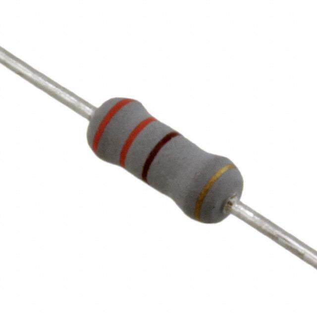
ICGOO电子元器件商城为您提供MP915-0.75-1%由Caddock设计生产,在icgoo商城现货销售,并且可以通过原厂、代理商等渠道进行代购。 MP915-0.75-1%价格参考。CaddockMP915-0.75-1%封装/规格:通孔电阻器, 750 mOhms ±1% 15W TO-126-2 通孔电阻器 防潮,非电感 厚膜。您可以下载MP915-0.75-1%参考资料、Datasheet数据手册功能说明书,资料中有MP915-0.75-1% 详细功能的应用电路图电压和使用方法及教程。
品牌为Caddock Electronics Inc.、分类为通孔电阻器、型号为MP915-0.75-1%的电阻器,主要应用于对精度和稳定性要求较高的电子设备和系统中。该型号为精密金属膜电阻,具备±1%的阻值公差,额定功率为0.75瓦,采用通孔封装,适合需要良好散热性和稳定性的电路设计。

其典型应用场景包括:

1. 测试与测量设备:如万用表、示波器、信号发生器等,用于确保测量精度和长期稳定性。

2. 工业控制系统:在PLC(可编程逻辑控制器)、传感器模块、工业仪表中作为精密反馈或分压元件。

3. 电源管理电路:用于稳压电源、DC-DC转换器中的电流检测或电压调节部分。

4. 音频设备:高保真音响系统中用于信号处理电路,确保音频信号的高保真传输。

5. 航空航天与军工设备:因其可靠性高,适用于对元器件性能要求严苛的高端领域。

该电阻器具有良好的温度系数和长期稳定性,适合在复杂环境条件下工作,是高精度、中功率应用的理想选择。
| 参数 | 数值 |
| 产品目录 | |
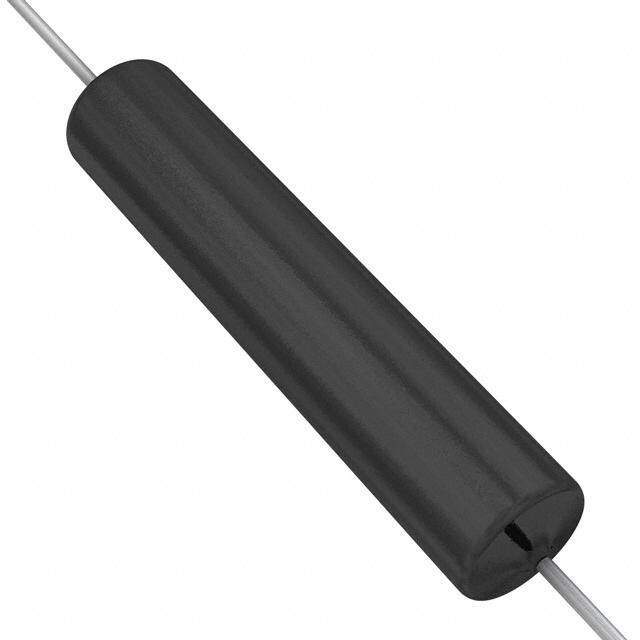
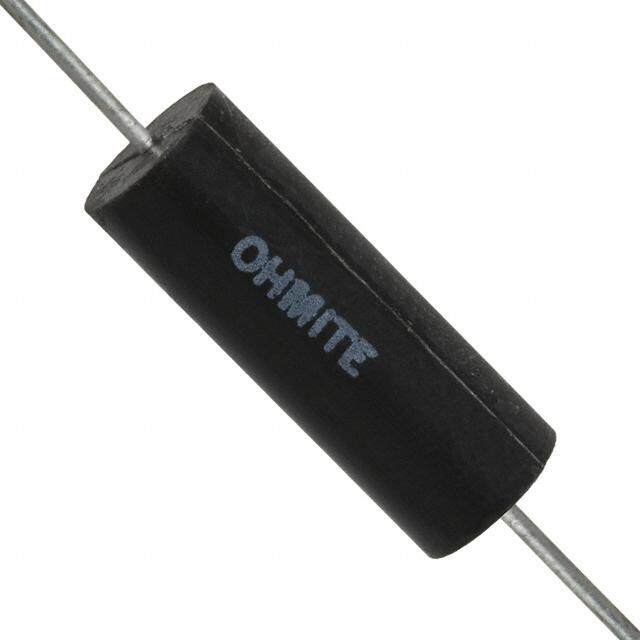
| 描述 | RES 0.75 OHM 15W 1% TO126厚膜电阻器 - 透孔 0.75 ohm 15W 1% TO-126 PKG PWR FILM |
| 产品分类 | |
| 品牌 | Caddock |
| 产品手册 | |
| 产品图片 |
|
| rohs | RoHS 合规性豁免含铅 / 符合限制有害物质指令(RoHS)规范要求 |
| 产品系列 | 薄膜电阻器,厚膜电阻器 - 透孔,Caddock MP915-0.75-1%Kool-Pak®MP900 |
| 数据手册 | |
| 产品型号 | MP915-0.75-1% |
| 产品 | Thick Film Resistors Leaded |
| 产品种类 | 厚膜电阻器 - 透孔 |
| 供应商器件封装 | TO-126 |
| 其它名称 | MP915-0.75-1%-ND |
| 功率(W) | 15W |
| 功率额定值 | 15 W |
| 包装 | 管件 |
| 商标 | Caddock |
| 外壳宽度 | 2.79 mm |
| 外壳长度 | 8.12 mm |
| 外壳高度 | 11.18 mm |
| 大小/尺寸 | 0.320" 长 x 0.110" 宽(8.12mm x 2.79mm) |
| 容差 | 1 % |
| 封装 | Tube |
| 封装/外壳 | TO-126-2 |
| 工作温度范围 | - 55 C to + 150 C |
| 工厂包装数量 | 50 |
| 引线直径 | 0.64 mm |
| 引线间隔 | 5.08 mm |
| 成分 | 厚膜 |
| 标准包装 | 50 |
| 温度系数 | - 20 PPM / C, + 80 PPM / C |
| 特性 | 电流感应,非电感 |
| 电压额定值 | 200 V |
| 电阻 | 0.75 Ohms |
| 电阻(Ω) | 0.75 |
| 端子数 | 2 |
| 端接类型 | Radial |
| 类型 | Kool-Pak Power Film Resistors |
| 系列 | MP900 |
| 高度 | 0.450"(11.44mm) |


- 商务部:美国ITC正式对集成电路等产品启动337调查
- 曝三星4nm工艺存在良率问题 高通将骁龙8 Gen1或转产台积电
- 太阳诱电将投资9.5亿元在常州建新厂生产MLCC 预计2023年完工
- 英特尔发布欧洲新工厂建设计划 深化IDM 2.0 战略
- 台积电先进制程称霸业界 有大客户加持明年业绩稳了
- 达到5530亿美元!SIA预计今年全球半导体销售额将创下新高
- 英特尔拟将自动驾驶子公司Mobileye上市 估值或超500亿美元
- 三星加码芯片和SET,合并消费电子和移动部门,撤换高东真等 CEO
- 三星电子宣布重大人事变动 还合并消费电子和移动部门
- 海关总署:前11个月进口集成电路产品价值2.52万亿元 增长14.8%


PDF Datasheet 数据手册内容提取
® MP900 and MP9000 Series Kool-Pak Power Film Resistors TO-126, TO-220 and TO-247 Style Page 1 of 2 MP916 Standard Resistance Values: Tolerance MP916 ±5% Standard (20% is available). 0.010 Ω 5% 0.015 Ω 5% MP915, MP925, and MP930 Standard Resistance Values: Tolerance MP915, MP925, and MP930 ±1% Standard - except as noted. (5% and 20% are available for most resistance values). 0.020 Ω 5% 0.33 Ω 7.50 Ω 50.0 Ω 500 Ω 10.0 K 0.025 Ω 5% 0.40 Ω 8.00 Ω 56.0 Ω 560 Ω 15.0 K 0.030 Ω 5% 0.50 Ω 10.0 Ω 75.0 Ω 750 Ω 20.0 K 0.033 Ω 5% 0.75 Ω 12.0 Ω 100 Ω 1.00 K 25.0 K 0.040 Ω 5% 1.00 Ω 15.0 Ω 120 Ω 1.50 K 30.0 K 0.050 Ω 1.50 Ω 20.0 Ω 150 Ω 2.00 K 33.0 K 0.075 Ω 2.00 Ω 25.0 Ω 200 Ω 2.50 K 40.0 K 0.10 Ω 2.50 Ω 27.0 Ω 250 Ω 3.00 K 47.0 K 0.15 Ω 3.00 Ω 30.0 Ω 300 Ω 3.30 K 50.0 K 0.20 Ω 3.30 Ω 33.0 Ω 330 Ω 4.00 K 56.0 K 0.25 Ω 4.00 Ω 40.0 Ω 400 Ω 5.00 K 68.0 K Low Cost Heat Sink Mountable Design featuring 0.30 Ω 5.00 Ω 47.0 Ω 470 Ω 7.50 K 75.0 K 82.0 K an Exposed Ceramic Heat Dissipating Mounting Surface 100 K Use your thermal design experience with power semiconductors in TO-126, TO-220, MP9100 Standard Resistance Values: and TO-247 style power packages to help you get the most out of this unique family of Tolerance MP9100 ±1% Standard. power resistors. The thermal design issues are the same where power handling 0.050 Ω 0.40 Ω 3.30 Ω 20.0 Ω 56.0 Ω capability is based on the case temperature which is maintained in your design. 0.075 Ω 0.50 Ω 4.00 Ω 25.0 Ω 75.0 Ω 0.10 Ω 0.75 Ω 5.00 Ω 27.0 Ω 100 Ω 0.15 Ω 1.00 Ω 7.50 Ω 30.0 Ω MP915 TO-126 Style Power Package 00..2205 ΩΩ 12..5000 ΩΩ 81.00.00 ΩΩ 3430..00 ΩΩ • 0.30 Ω 2.50 Ω 12.0 Ω 47.0 Ω 15 Watts at +25°C Case Temperature, derated to zero at +150°C. 0.33 Ω 3.00 Ω 15.0 Ω 50.0 Ω • Exposed Ceramic Heat Dissipating Mounting Surface. • Resistance Range of 0.020 ohm to 1 K. • Non-Inductive Design. For custom resistance values and tolerances contact applications engineering. MP916, MP925, and MP930 TO-220 Style Power Package • Up to 30 Watts at +25°C Case Temperature, derated to zero at +150°C. Ordering Information: • Exposed Ceramic Heat Dissipating Mounting Surface. MP915 - 50.0 - 1% • Resistance Range of 0.010 ohm to 100 K. Model Number: Tolerance • Non-Inductive Design. Resistor Value: Packaging: MP915, MP916, MP925, MP930 MP9100 TO-247 Style Power Package resistors are packaged in plastic shipping tubes, 50 pieces per tube. These resistors are available • 100 Watts at +25°C Case Temperature, derated to zero at +175°C. in a 50 piece minimum quantity and in full tube • Exposed Ceramic Heat Dissipating Mounting Surface. quantity increments (i.e. 50, 100, 150, etc.). The • Resistance Range of 0.050 ohm to 100 ohm. MP9100 resistors are packaged in plastic shipping • Non-Inductive Design. tubes, 25 pieces per tube. Construction of MP900 and MP9000 Series: New The MP900 and MP9000 Series Kool-Pak® Power Power Resistor Film Resistors are constructed with Caddock's with Micronox® resistance film fired onto a flat ceramic Exposed Ceramic substrate. The terminal attachment and resistance Heat Dissipating element geometry are configured to provide Mounting outstanding non-inductive performance. The Surface. ceramic substrate is positioned in the molded package such that the resistor element and terminal attachment areas on the substrate are encapsulated in the molded body with the other side of the ceramic being exposed flush with the back mounting surface of the device. This construction is covered by one or more issued patents, also patents pending. Sales and Applications Engineering ELECTRONICS, INC. 17271 North Umpqua Hwy. Roseburg, Oregon 97470-9422 e-mail: caddock@caddock.com • web: www.caddock.com Phone: (541) 496-0700 For Caddock Distributors listed by country see caddock.com/contact/dist.html Fax: (541) 496-0408 © 2003-2017 Caddock Electronics, Inc. 28_IL134.0517
Page 2 of 2 MNood.el Package MRine.sistancMeax. RPoatwinegr VoMlataxg.e TFhilemrm (Ja)lR tRθoJe CCs aisstea n(Cc)e MaxT . M T A e X mp. Dimensions Comments MP915 TO-126 Style 0.020 Ω 1.00 K 15 Watts* 200 8.33°C/Watt 150°C Figure 1 Ceramic mounting surface MP916 TO-220 Style 0.010 Ω 0.019 Ω 16 Watts* PLiomwiteerd 7.81°C/Watt 150°C Figure 2 Ceramic mounting surface MP925 TO-220 Style 5.00K 100 K 25 Watts* 500 5.00°C/Watt 150°C Figure 2 Ceramic mounting surface MP930 TO-220 Style 0.020 Ω 4.99 K 30 Watts* 250 4.17°C/Watt 150°C Figure 2 Ceramic mounting surface MP9100 TO-247 Style 0.050 Ω 100 Ω 100 Watts* PLiomwiteerd 1.50°C/Watt 175°C Figure 3 Ceramic mounting surface Derating Curve Specifications: 100 % 80 * Derating Using Case Temperature (TC): Temperature Coefficient for MP915, MP916, G, WER RATIN 4600 AbTahll sepe ocdaw usepero tanen mcdap aseesrsa toetucmrieap teiesrd am touevraees ruluosraeinddg r atahtt eitnh dgees c raaertnient egdr e coruaf rttvehede. MTCP 9re2f5e,r eanncde Md Pto9 +3205:°C, ∆R taken at +150°C PO 20 A B ceramic mounting surface, with the part properly 0.50 ohms and above, -20 to +80 ppm/°C mounted and under electrical load. Without a heat sink, 0.050 ohm to 0.49 ohms, 0 to +200 ppm/°C 0 25 100 150 175 when in free air at +25°C, the MP915 is rated for 1.25 0.020 ohm to 0.049 ohm, 0 to +300 ppm/°C CASE TEMPERATURE, °C watts, the MP916, MP925, MP930 are rated for 2.25 0.010 ohm to 0.019 ohm, 0 to +500 ppm/°C watts, and the MP9100 is rated for 3.5 watts. A - MP915, MP916, MP925, MP930 Max. Temperature, TMax = 150°C B - MP9100 Max. Temperature, TMax = 175°C Temperature Coefficient for MP9100: TC referenced to +25°C, ∆R taken at +175°C The thermal design should satisfy the following equation: Copaesrea tTinegm tpeemrapteurraet u(Trec )r a+n g[Teh oefr mthael aRpepsliicsatatinocne. (RθJC) x power applied (Watts)] ≤ TMAX considering the full 0.50 ohms and above, -20 to +80 ppm/°C 0.050 ohm to 0.49 ohms, 0 to +150 ppm/°C Mounting Note: Mount on a smooth, clean, and flat heat sink surface with a thermal interface material, such as thermal grease. The entire exposed ceramic portion must be in thermal contact with the heat sink. When Operating Temperature: -55°C to TMAX screw mounting, use a compression washer which provides a mounting force of 150 to 300 pounds (665 to 1330 N). This will provide sufficient pressure on the package over time and through large temperature varia- Inductance: MP915, MP916, MP925, and MP930 tions to maintain the maximum power dissipation capability. Mounting torque to avoid package damage is 8 10nH typical; MP9100, 20nH typical, in series when in-lbs. (0.90 N-m). If a spring clip is used, a clip force of 8 to 30 pounds (35 to 130 N) is recommended to be applied to the center of the package. The clip should be round or smooth in the contact area to avoid concen- measured at a point 0.2 inches from the resistor trating the load on a small point of the plastic body of the package. Another mounting option is to use a body. pressure bar method which can achieve a greater mounting force with a greater contact area. For additional applications information regarding mounting and pulse handling see the Caddock DWV: The dielectric strength rating of 1500 VrmsAC Applications Notes at caddock.com or contact Applications Engineering. is based upon connections made between terminals shorted, and the metal surface the part is .(029.349 ± ±.0.1004) DIA. (.382.102 ± ±.0.2160) .(121.709 ± ±.0.2160) mounted to or a metal clip in contact with the top CL surface of the part. + .440 ±.010 Insulation Resistance: 10,000 Megohms min. Figure 1 .(028.003 ± ±.0.5210) M0.P1901Ω5 .(121.952 ± ±.0.2160) (11.18 ±.26) The resistor element is electrically isolated from TO-126 Style 1% the mounting surface. .053 ± .007 MP915 ( 1 .14.5403 ±±.10.5207) .(013.305 ± ±.0 .0148) Load Stability: 2,000 hours at rated power. (.76 ± .10) ∆R ±(1.0 percent + 0.0005 ohm) max. Power .025 ± .004 (.64 ±.10) rating dependent upon case temperature. See .200 ±.010 (5.08 ±.26) .058 ±.007 (1.47 ±.18) derating curve. .125 ±.004 .410 ±.010 .125 ±.010 (3.18 ±.10) DIA. (10.41 ±.26) (3.18 ±.26) Momentary Overload: 1.5 times rated power with CL applied voltage not to exceed 1.5 times maximum continuous operating voltage for 5 seconds. ∆R FTOig-u2r2e0 2 S tyle MP930 ( 3.1.1285 ±±..2061)0 ( 1 .66.4206 ±±..02160) ±(0.5 percent + 0.0005 ohm) max. .130 ±.030 10.0 MP916, MP925 (3.30 ±.76) 1% Moisture Resistance: Mil-Std-202, Method 106. and MP930 .053 ± .007 ∆R ±(0.5 percent + 0.0005 ohm) max. (1.35 ± .18) (1 2.5.7000 ±±1.0.2570) .(0.7360 ±± ..01004) T∆hRe ±rm(0a.5l Spehroccekn:t +M 0il-.S00td0-52 0o2h, mM)e tmhoadx .107, Cond. F. .200 ±.010 .025 ± .004 (.64 ±.10) (5.08 ±.26) .070 ±.010 (1.78 ±.26) Shock: 100G, Mil-Std-202, Method 213, Cond. I. ∆R ±(0.4 percent + 0.0005 ohm) max. 0.620 ± 0.010 0.195 ± 0.010 (30..6134 3± ±0 .01.00)0 4Dia. (15.75C L± 0.26) (4.95 ± 0.26) Vibration, High Frequency: Mil-Std-202, Method 0.210 ± 0.010 204, Cond. D. ∆R ±(0.4 percent + 0.0005 ohm) (5.33 ± 0.26) max. Figure 3 0.815 ± 0.010 TO-247 Style MP 9100 (20.70 ± 0.26) Terminal Strength: Mil-Std-202, Method 211, 0.110 ± 0.030 50.0 Cond. A (Pull Test) 5 lbs. ∆R ±(0.2 percent MP9100 (2.79 ± 0.76) 1% + 0.0005 ohm) max. 0.143 ± 0.007 0.570 ± 0.050 (3.63 ± 0.18) Terminal Material: Solderable (14.48 ± 1.27) 0.060 ± 0.004 (1.52 ± 0.10) Measurement Note: For these specifications, 0.400 ± 0.010 0(.003.821 + +00.0.1004 // --00..2061)0 resistance measurement shall be made at a point DIMENSIONS IN INCHES AND (MILLIMETERS) (10.16 ± 0.26) 0(2.0.4915 ±± 00..2061)0 0.2 inch (5.08 mm) from the resistor body. Sales and Applications Engineering ELECTRONICS, INC. 17271 North Umpqua Hwy. Roseburg, Oregon 97470-9422 e-mail: caddock@caddock.com • web: www.caddock.com Phone: (541) 496-0700 For Caddock Distributors listed by country see caddock.com/contact/dist.html Fax: (541) 496-0408 © 2003-2017 Caddock Electronics, Inc. 28_IL134.0517
Mouser Electronics Authorized Distributor Click to View Pricing, Inventory, Delivery & Lifecycle Information: C addock: MP930-4.0-1% MP930-0.04-5% MP930-0.33 1% MP930-0.075-1% MP925-30.0K-1% MP930-500-1% MP930-100- 1% MP930-1.5-1% MP915-7.5-1% MP915-0.40 1% MP915-470-1% MP915-4-1% MP930-3.0K-1% MP930-2.50-1% MP915-500-1% MP925-100K-1% MP930-150-1% MP915-100-1% MP930-200-1% MP930-0.75-1% MP930-1.5K- 1% MP9100-100-1% MP9100-30.0-1% MP9100-33-1% MP9100-15-1% MP9100-40.0-1% MP9100-5.6-1% MP925 5.10K 1% MP915-0.15-1% MP915-0.33-1% MP915-200-1% MP930-56-1% MP930-30.0-1% MP915-15-1% MP9100-7.50-1% MP930-39-5% MP925-75.0K-1% MP930-33.0-1% MP930-3.30-1% MP930-15.0-1% MP925-7.5K- 1% MP925 82.0K 1% MP9100-2.5-1% MP9100-8.00-1% MP9100-0.25-1% MP9100-12.0-1% MP930-0.40-1% MP930-0.25-1% MP915-0.75-1% MP915-560- 1% MP930-3.3K-1% MP9100-3-1% MP9100-0.75-1% MP9100-1.50- 1% MP9100-0.3-1% MP9100-0.4-1% MP930-250-1% MP915-0.025-5% MP930-0.15-1% MP915-250-1% MP915- 0.020-5% MP915-0.050-1% MP915-0.10-1% MP915-0.20-1% MP915-0.50-1% MP915-1.00-1% MP915-2.00-1% MP915-5.00-1% MP915-10.0-1% MP915-20.0-1% MP915-25.0-1% MP915-50.0-1% MP915-75.0-1% MP915-1.00K- 1% MP916-0.010-5% MP930-0.020-5% MP930-0.050-1% MP930-0.10-1% MP930-0.20-1% MP930-0.50-1% MP930-1.00-1% MP930-2.00-1% MP930-5.00-1% MP930-10.0-1% MP930-20.0-1% MP930-25.0-1% MP930-50.0- 1% MP930-75.0-1% MP930-1.00K-1% MP930-2.00K-1% MP925-5.00K-1% MP925-10.0K-1% MP925-20.0K-1% MP925-50.0K-1% MP9100-0.050-1% MP9100-0.10-1% MP9100-0.20-1% MP9100-0.50-1% MP9100-1.00-1% MP9100-2.00-1%