ICGOO在线商城 > 集成电路(IC) > PMIC - 显示器驱动器 > MM5483V/NOPB

 Datasheet下载
- 型号: MM5483V/NOPB
- 制造商: Texas Instruments
- 库位|库存: xxxx|xxxx
- 要求:
| 数量阶梯 | 香港交货 | 国内含税 |
| +xxxx | $xxxx | ¥xxxx |
查看当月历史价格
查看今年历史价格
MM5483V/NOPB产品简介:
ICGOO电子元器件商城为您提供MM5483V/NOPB由Texas Instruments设计生产,在icgoo商城现货销售,并且可以通过原厂、代理商等渠道进行代购。 MM5483V/NOPB价格参考¥19.70-¥36.77。Texas InstrumentsMM5483V/NOPB封装/规格:PMIC - 显示器驱动器, 。您可以下载MM5483V/NOPB参考资料、Datasheet数据手册功能说明书,资料中有MM5483V/NOPB 详细功能的应用电路图电压和使用方法及教程。
| 参数 | 数值 |
| 产品目录 | 集成电路 (IC)半导体 |
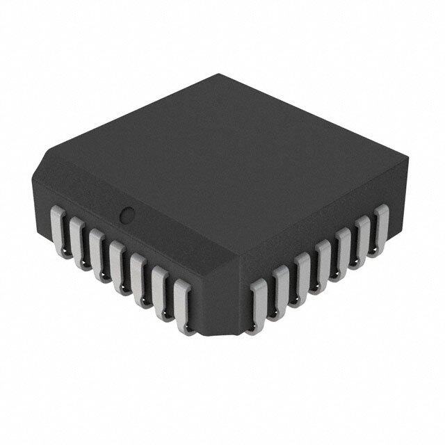
| 描述 | IC DRIVER LIQ CRYSTL DISP 44PLCC显示驱动器和控制器 Liquid Crystal Display Driver 44-PLCC -40 to 85 |
| 产品分类 | |
| 品牌 | Texas Instruments |
| 产品手册 | |
| 产品图片 |
|
| rohs | 符合RoHS无铅 / 符合限制有害物质指令(RoHS)规范要求 |
| 产品系列 | 驱动器IC,显示驱动器和控制器,Texas Instruments MM5483V/NOPBCOPS™ |
| 数据手册 | |
| 产品型号 | MM5483V/NOPB |
| 产品 | LCD Display Drivers |
| 产品种类 | 显示驱动器和控制器 |
| 供应商器件封装 | 44-PLCC(16.58x16.58) |
| 其它名称 | *MM5483V/NOPB |
| 包装 | 管件 |
| 商标 | Texas Instruments |
| 安装类型 | 表面贴装 |
| 安装风格 | SMD/SMT |
| 封装 | Tube |
| 封装/外壳 | 44-LCC(J 形引线) |
| 封装/箱体 | PLCC-44 |
| 工作温度 | -40°C ~ 85°C |
| 工厂包装数量 | 25 |
| 接口 | 串行 |
| 数字或字符 | 4.5 位数字 |
| 显示类型 | LCD |
| 最大功率耗散 | 350 mW |
| 最大工作温度 | + 85 C |
| 最小工作温度 | - 40 C |
| 标准包装 | 25 |
| 电压-电源 | 3 V ~ 10 V |
| 电流-电源 | - |
| 电源电压 | 3 V to 10 V |
| 电源电流 | 10 uA |
| 系列 | MM5483 |
| 配置 | 7 段显示 + DP,字母数字和条形图 |


.jpg)


- 商务部:美国ITC正式对集成电路等产品启动337调查
- 曝三星4nm工艺存在良率问题 高通将骁龙8 Gen1或转产台积电
- 太阳诱电将投资9.5亿元在常州建新厂生产MLCC 预计2023年完工
- 英特尔发布欧洲新工厂建设计划 深化IDM 2.0 战略
- 台积电先进制程称霸业界 有大客户加持明年业绩稳了
- 达到5530亿美元!SIA预计今年全球半导体销售额将创下新高
- 英特尔拟将自动驾驶子公司Mobileye上市 估值或超500亿美元
- 三星加码芯片和SET,合并消费电子和移动部门,撤换高东真等 CEO
- 三星电子宣布重大人事变动 还合并消费电子和移动部门
- 海关总署:前11个月进口集成电路产品价值2.52万亿元 增长14.8%


PDF Datasheet 数据手册内容提取
MM5483 www.ti.com SNLS368E–JULY2000–REVISEDMARCH2013 MM5483 Liquid Crystal Display Driver CheckforSamples:MM5483 FEATURES DESCRIPTION 1 • SerialDataInput The MM5483 is a monolithic integrated circuit utilizing 23 CMOS metal-gate low-threshold enhancement mode • SerialDataOutput devices. It is available in a 40-pin PDIP package. The • WidePowerSupplyOperation chip can drive up to 31 segments of LCD and can be • TTLCompatibility cascaded to increase this number. This chip is capable of driving a 4½-digit 7-segment display with • 31SegmentOutputs minimal interface between the display and the data • AlphanumericandBarGraphCapability source. • CascadeCapability TheMM5483storesthedisplaydatainlatchesafterit is latched in, and holds the data until another load APPLICATIONS pulseisreceived. • COPS™orMicroprocessorDisplays • IndustrialControlIndicator • DigitalClock,Thermometer,Counter, Voltmeter • InstrumentationReadouts • RemoteDisplays Block Diagram Figure1. MM5483BlockDiagram 1 Pleasebeawarethatanimportantnoticeconcerningavailability,standardwarranty,anduseincriticalapplicationsof TexasInstrumentssemiconductorproductsanddisclaimerstheretoappearsattheendofthisdatasheet. COPSisatrademarkofTexasInstruments. 2 Allothertrademarksarethepropertyoftheirrespectiveowners. 3 PRODUCTIONDATAinformationiscurrentasofpublicationdate. Copyright©2000–2013,TexasInstrumentsIncorporated Products conform to specifications per the terms of the Texas Instruments standard warranty. Production processing does not necessarilyincludetestingofallparameters.
MM5483 SNLS368E–JULY2000–REVISEDMARCH2013 www.ti.com Connection Diagrams Figure2. Dual-In-LinePackage TopView SeePackageNumberNFJ0040A Figure3. SeePackageNumberFN0044A Thesedeviceshavelimitedbuilt-inESDprotection.Theleadsshouldbeshortedtogetherorthedeviceplacedinconductivefoam duringstorageorhandlingtopreventelectrostaticdamagetotheMOSgates. 2 SubmitDocumentationFeedback Copyright©2000–2013,TexasInstrumentsIncorporated ProductFolderLinks:MM5483
MM5483 www.ti.com SNLS368E–JULY2000–REVISEDMARCH2013 Absolute Maximum Ratings (1)(2) VoltageatAnyPin V toV +10V SS SS OperatingTemperature −40°Cto+85°C StorageTemperature −65°Cto+150°C PowerDissipation 300mWat+85°C 350mWat+25°C JunctionTemperature +150°C LeadTemperature (Soldering,10seconds) 300°C (1) “AbsoluteMaximumRatings”arethosevaluesbeyondwhichthesafetyofthedevicecannotbeensured.Theyarenotmeanttoimply thatthedevicesshouldbeoperatedattheselimits.Thetableof“ElectricalCharacteristics”specifiesconditionsofdeviceoperation. (2) IfMilitary/Aerospacespecifieddevicesarerequired,pleasecontacttheTISalesOffice/Distributorsforavailabilityandspecifications. DC Electrical Characteristics T withinoperatingrange,V =3.0Vto10V,V =0V,unlessotherwisespecified A DD SS Parameter Conditions Min Typ Max Units PowerSupply 3.0 10 V AllOutputsBits=Open,DataOut=Open, BP_Out=Open,ClockIn=0V, DataIn=0V,DataLoad=0V, OscIn=0V,BP_In=32Hz AverageSupplyCurrent,I DD V =3.0V 1.5 2.5 µA DD V =5.0V 10 µA DD V =10.0V 40 µA DD InputVoltageLevels Load,Clock,Data Logic“0” V =5.0V 0.9 V DD Logic“1” V =5.0V 2.4 V DD Logic“0” V =3.0V 0.4 V DD Logic“1” V =3.0V 2.0 V DD OutputCurrentLevels(1) SegmentsandDataOut Sink V =3.0V,V =0.3V 20 µA DD OUT Source V =3.0V,V =2.7V 20 µA DD OUT BPOutSink V =3.0V,V =0.3V 320 µA DD OUT BPOutSource V =3.0V,V =2.7V 320 µA DD OUT (1) Outputoffsetvoltageis±50mVwithC =250pF,C =8750pF. SEGMENT BP AC Electrical Characteristics V ≥4.7V,V =0Vunlessotherwisespecified DD SS Symbol Parameter Min Typ Max Units f ClockFrequency,V =3V 500 kHz C DD t ClockPeriodHigh (1)(2)500 ns CH t ClockPeriodLow 500 ns CL t DataSet-UpbeforeClock 300 ns DS t DataHoldTimeafterClock 100 ns DH t MinimumLoadPulseWidth 500 ns LW t LoadtoClock 400 ns LTC t ClocktoDataValid 400 750 ns CDO (1) ACinputwaveformspecificationfortestpurpose:t ≤20ns,t ≤20ns,f=500kHz,50%±10%dutycycle. r f (2) Clockinputriseandfalltimesmustnotexcced300ms. Copyright©2000–2013,TexasInstrumentsIncorporated SubmitDocumentationFeedback 3 ProductFolderLinks:MM5483
MM5483 SNLS368E–JULY2000–REVISEDMARCH2013 www.ti.com FUNCTIONAL DESCRIPTION A block diagram for the MM5483 is shown in Figure 1 and a package pinout is shown in Figure 3. Figure 4 shows a possible 3-wire connection system with a typical signal format for Figure 4. Shown in Figure 5, the load input is an asynchronous input and lets data through from the shift register to the output buffers any time it is high. The load input can be connected to V for 2-wire control as shown in Figure 6. In the 2-wire control mode, DD 31 bits (or less depending on the number of segments used) of data are clocked into the MM5483 in a short time frame (with less than 0.1 second there probably will be no noticeable flicker) with no more clocks until new information is to be displayed. If data was slowly clocked in, it can be seen to “walk” across the display in the 2- wire mode. An AC timing diagram can be seen in Figure 7. It should be noted that data out is not a TTL- compatibleoutput. Figure4. Three-WireControlMode Figure5. DataFormatDiagram Figure6. Two-WireControlMode 4 SubmitDocumentationFeedback Copyright©2000–2013,TexasInstrumentsIncorporated ProductFolderLinks:MM5483
MM5483 www.ti.com SNLS368E–JULY2000–REVISEDMARCH2013 Figure7. TimingDiagram Copyright©2000–2013,TexasInstrumentsIncorporated SubmitDocumentationFeedback 5 ProductFolderLinks:MM5483
MM5483 SNLS368E–JULY2000–REVISEDMARCH2013 www.ti.com REVISION HISTORY ChangesfromRevisionD(March2013)toRevisionE Page • ChangedlayoutofNationalDataSheettoTIformat............................................................................................................ 5 6 SubmitDocumentationFeedback Copyright©2000–2013,TexasInstrumentsIncorporated ProductFolderLinks:MM5483
PACKAGE OPTION ADDENDUM www.ti.com 22-Dec-2018 PACKAGING INFORMATION Orderable Device Status Package Type Package Pins Package Eco Plan Lead/Ball Finish MSL Peak Temp Op Temp (°C) Device Marking Samples (1) Drawing Qty (2) (6) (3) (4/5) MM5483N/NOPB OBSOLETE PDIP NFJ 40 TBD Call TI Call TI -40 to 85 MM5483N MM5483V/NOPB ACTIVE PLCC FN 44 25 Green (RoHS CU SN Level-3-245C-168 HR -40 to 85 MM5483V & no Sb/Br) (1) The marketing status values are defined as follows: ACTIVE: Product device recommended for new designs. LIFEBUY: TI has announced that the device will be discontinued, and a lifetime-buy period is in effect. NRND: Not recommended for new designs. Device is in production to support existing customers, but TI does not recommend using this part in a new design. PREVIEW: Device has been announced but is not in production. Samples may or may not be available. OBSOLETE: TI has discontinued the production of the device. (2) RoHS: TI defines "RoHS" to mean semiconductor products that are compliant with the current EU RoHS requirements for all 10 RoHS substances, including the requirement that RoHS substance do not exceed 0.1% by weight in homogeneous materials. Where designed to be soldered at high temperatures, "RoHS" products are suitable for use in specified lead-free processes. TI may reference these types of products as "Pb-Free". RoHS Exempt: TI defines "RoHS Exempt" to mean products that contain lead but are compliant with EU RoHS pursuant to a specific EU RoHS exemption. Green: TI defines "Green" to mean the content of Chlorine (Cl) and Bromine (Br) based flame retardants meet JS709B low halogen requirements of <=1000ppm threshold. Antimony trioxide based flame retardants must also meet the <=1000ppm threshold requirement. (3) MSL, Peak Temp. - The Moisture Sensitivity Level rating according to the JEDEC industry standard classifications, and peak solder temperature. (4) There may be additional marking, which relates to the logo, the lot trace code information, or the environmental category on the device. (5) Multiple Device Markings will be inside parentheses. Only one Device Marking contained in parentheses and separated by a "~" will appear on a device. If a line is indented then it is a continuation of the previous line and the two combined represent the entire Device Marking for that device. (6) Lead/Ball Finish - Orderable Devices may have multiple material finish options. Finish options are separated by a vertical ruled line. Lead/Ball Finish values may wrap to two lines if the finish value exceeds the maximum column width. Important Information and Disclaimer:The information provided on this page represents TI's knowledge and belief as of the date that it is provided. TI bases its knowledge and belief on information provided by third parties, and makes no representation or warranty as to the accuracy of such information. Efforts are underway to better integrate information from third parties. TI has taken and continues to take reasonable steps to provide representative and accurate information but may not have conducted destructive testing or chemical analysis on incoming materials and chemicals. TI and TI suppliers consider certain information to be proprietary, and thus CAS numbers and other limited information may not be available for release. In no event shall TI's liability arising out of such information exceed the total purchase price of the TI part(s) at issue in this document sold by TI to Customer on an annual basis. Addendum-Page 1
MECHANICAL DATA N0040A N40A (Rev E) www.ti.com
None
4215154/A 04/2017 PACKAGE OUTLINE FN0044A PLCC - 4.57 mm max height SCALE 0.800 PLASTIC CHIP CARRIER B .650-.656 .180 MAX [16.51-16.66] [4.57] .020 MIN NOTE 3 A [0.51] (.008) 6 1 44 40 [0.2] 7 39 PIN 1 ID .650-.656 (OPTIONAL) .582-.638 [16.51-16.66] [14.79-16.20] NOTE 3 17 29 18 28 .090-.120 TYP [2.29-3.04] 44X .026-.032 [0.66-0.81] C SEATING PLANE 44X .013-.021 .004 [0.1] C [0.33-0.53] 40X .050 [1.27] .007 [0.18] C A B .685-.695 [17.40-17.65] TYP 4215154/A 04/2017 NOTES: 1. All linear dimensions are in inches. Any dimensions in brackets are in millimeters. Any dimensions in parenthesis are for reference only. Controlling dimensions are in inches. Dimensioning and tolerancing per ASME Y14.5M. 2. This drawing is subject to change without notice. 3. Dimension does not include mold protrusion. Maximum allowable mold protrusion .01 in [0.25 mm] per side. 4. Reference JEDEC registration MS-018. www.ti.com
4215154/A 04/2017 EXAMPLE BOARD LAYOUT FN0044A PLCC - 4.57 mm max height PLASTIC CHIP CARRIER SYMM 44X (.093 ) [2.35] 6 1 44 40 7 39 44X (.030 ) [0.75] SYMM (.64 ) [16.2] 40X (.050 ) [1.27] 17 29 (R.002 ) TYP [0.05] 18 28 (.64 ) [16.2] LAND PATTERN EXAMPLE EXPOSED METAL SHOWN SCALE:4X .002 MAX EXPOSED METAL .002 MIN EXPOSED METAL [0.05] [0.05] ALL AROUND ALL AROUND METAL SOLDER MASK SOLDER MASK METAL UNDER OPENING OPENING SOLDER MASK NON SOLDER MASK SOLDER MASK DEFINED DEFINED (PREFERRED) SOLDER MASK DETAILS 4215154/A 04/2017 NOTES: (continued) 5. Publication IPC-7351 may have alternate designs. 6. Solder mask tolerances between and around signal pads can vary based on board fabrication site. www.ti.com
EXAMPLE STENCIL DESIGN FFNN00004444AA PPLLCCCC -- 44..5577 mmmm mmaaxx hheeiigghhtt PPLLAASSTTIICC CCHHIIPP CCAARRRRIIEERR SYMM 44X (.093 ) 6 1 44 40 [2.35] 7 39 44X (.030 ) [0.75] SYMM (.64 ) [16.2] 40X (.050 ) [1.27] 17 29 (R.002 ) TYP [0.05] 18 28 (.64 ) [16.2] SOLDER PASTE EXAMPLE BASED ON 0.125 mm THICK STENCIL SCALE:4X 4215154/A 04/2017 NOTES: (continued) 7. Laser cutting apertures with trapezoidal walls and rounded corners may offer better paste release. IPC-7525 may have alternate design recommendations. 8. Board assembly site may have different recommendations for stencil design. www.ti.com
IMPORTANTNOTICEANDDISCLAIMER TIPROVIDESTECHNICALANDRELIABILITYDATA(INCLUDINGDATASHEETS),DESIGNRESOURCES(INCLUDINGREFERENCE DESIGNS),APPLICATIONOROTHERDESIGNADVICE,WEBTOOLS,SAFETYINFORMATION,ANDOTHERRESOURCES“ASIS” ANDWITHALLFAULTS,ANDDISCLAIMSALLWARRANTIES,EXPRESSANDIMPLIED,INCLUDINGWITHOUTLIMITATIONANY IMPLIEDWARRANTIESOFMERCHANTABILITY,FITNESSFORAPARTICULARPURPOSEORNON-INFRINGEMENTOFTHIRD PARTYINTELLECTUALPROPERTYRIGHTS. TheseresourcesareintendedforskilleddevelopersdesigningwithTIproducts.Youaresolelyresponsiblefor(1)selectingtheappropriate TIproductsforyourapplication,(2)designing,validatingandtestingyourapplication,and(3)ensuringyourapplicationmeetsapplicable standards,andanyothersafety,security,orotherrequirements.Theseresourcesaresubjecttochangewithoutnotice.TIgrantsyou permissiontousetheseresourcesonlyfordevelopmentofanapplicationthatusestheTIproductsdescribedintheresource.Other reproductionanddisplayoftheseresourcesisprohibited.NolicenseisgrantedtoanyotherTIintellectualpropertyrightortoanythird partyintellectualpropertyright.TIdisclaimsresponsibilityfor,andyouwillfullyindemnifyTIanditsrepresentativesagainst,anyclaims, damages,costs,losses,andliabilitiesarisingoutofyouruseoftheseresources. TI’sproductsareprovidedsubjecttoTI’sTermsofSale(www.ti.com/legal/termsofsale.html)orotherapplicabletermsavailableeitheron ti.comorprovidedinconjunctionwithsuchTIproducts.TI’sprovisionoftheseresourcesdoesnotexpandorotherwisealterTI’sapplicable warrantiesorwarrantydisclaimersforTIproducts. MailingAddress:TexasInstruments,PostOfficeBox655303,Dallas,Texas75265 Copyright©2018,TexasInstrumentsIncorporated