
 Datasheet下载
- 型号: MLH100PGL01A
- 制造商: Honeywell Solid State Electronics
- 库位|库存: xxxx|xxxx
- 要求:
| 数量阶梯 | 香港交货 | 国内含税 |
| +xxxx | $xxxx | ¥xxxx |
查看当月历史价格
查看今年历史价格
MLH100PGL01A产品简介:
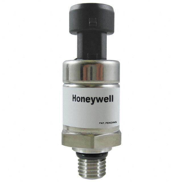
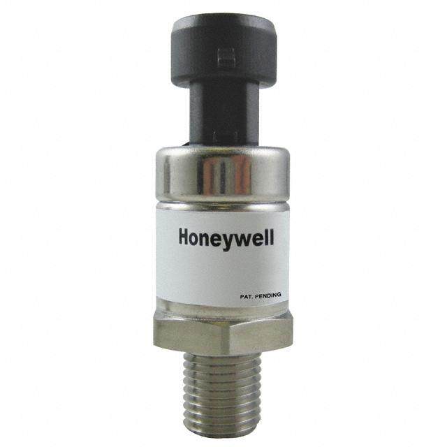
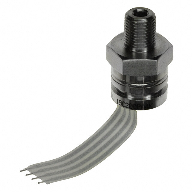
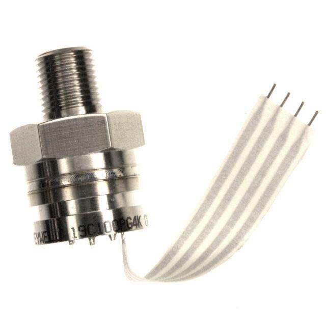
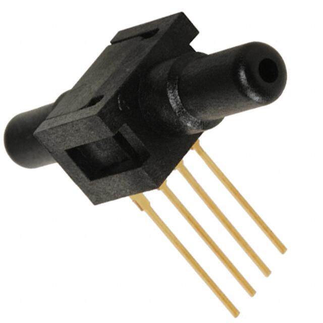
ICGOO电子元器件商城为您提供MLH100PGL01A由Honeywell Solid State Electronics设计生产,在icgoo商城现货销售,并且可以通过原厂、代理商等渠道进行代购。 MLH100PGL01A价格参考。Honeywell Solid State ElectronicsMLH100PGL01A封装/规格:压力传感器,变送器, 排气式压力计 压力 传感器 100 PSI(689.48 kPa) 公型 - 1/4"(6.35mm) NPT 0.5 V ~ 4.5 V 圆柱型,金属。您可以下载MLH100PGL01A参考资料、Datasheet数据手册功能说明书,资料中有MLH100PGL01A 详细功能的应用电路图电压和使用方法及教程。
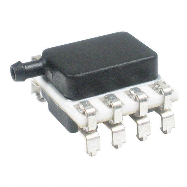
Honeywell Sensing and Productivity Solutions 旗下的 MLH100PGL01A 是一款压力传感器/变送器,主要用于工业自动化和过程控制领域。该型号属于表压型传感器,测量范围为0-100 psi,适用于多种气体和液体介质。

其典型应用场景包括:

1. 工业设备监测:用于监测液压系统、气动系统中的压力变化,确保设备稳定运行,如注塑机、空压机等。

2. 暖通空调系统(HVAC):用于监测空气或制冷剂压力,帮助实现系统高效运行和故障预警。

3. 能源与水处理:用于水泵控制、水压监测、管道压力检测等,保障供水系统的安全和效率。

4. 交通运输设备:在商用车辆、工程机械中用于制动系统、发动机管理系统中的压力测量。

5. 医疗设备:用于呼吸机、输液泵等设备中,对气体或液体压力进行精确控制和监测。

该传感器具有高精度、长期稳定性好、抗干扰能力强等特点,适合在工业环境中长期可靠运行。
| 参数 | 数值 |
| 产品目录 | |
| 描述 | SENSOR AMP 100PSI .5-4.5VDC OUT |
| 产品分类 | |
| 品牌 | Honeywell Sensing and Control |
| 数据手册 | http://sensing.honeywell.com/index.php?ci_id=54928http://sensing.honeywell.com/index.php?ci_id=51394 |
| 产品图片 |
|
| 产品型号 | MLH100PGL01A |
| rohs | 无铅 / 符合限制有害物质指令(RoHS)规范要求 |
| 产品系列 | MLH |
| 产品目录绘图 |
|
| 产品目录页面 | |
| 其它名称 | 480-2565 |
| 出厂设置 | - |
| 压力类型 | 压力计 |
| 封装/外壳 | 圆柱型,金属 |
| 工作压力 | 100 PSI |
| 工作温度 | -40°C ~ 125°C |
| 标准包装 | 25 |
| 电压-电源 | 5V |
| 端口尺寸 | 公型,1/4"(6.35mm)NPT |
| 端子类型 | 1m线缆 |
| 精度 | ±0.25%FSS |
| 输出 | 0.5 V ~ 4.5 V 比率 |


- 商务部:美国ITC正式对集成电路等产品启动337调查
- 曝三星4nm工艺存在良率问题 高通将骁龙8 Gen1或转产台积电
- 太阳诱电将投资9.5亿元在常州建新厂生产MLCC 预计2023年完工
- 英特尔发布欧洲新工厂建设计划 深化IDM 2.0 战略
- 台积电先进制程称霸业界 有大客户加持明年业绩稳了
- 达到5530亿美元!SIA预计今年全球半导体销售额将创下新高
- 英特尔拟将自动驾驶子公司Mobileye上市 估值或超500亿美元
- 三星加码芯片和SET,合并消费电子和移动部门,撤换高东真等 CEO
- 三星电子宣布重大人事变动 还合并消费电子和移动部门
- 海关总署:前11个月进口集成电路产品价值2.52万亿元 增长14.8%

PDF Datasheet 数据手册内容提取
Heavy Duty Pressure Transducers 32328895 MLH Series, 6 bar to 550 bar | 50 psi to 8000 psi Issue B Datasheet FEATURES • Pressure range of 6 bar to 550 bar | 50 psi to 8,000 psi • ±0.25% full scale accuracy Best Fit Straight Line (BFSL) • Total Error Band (TEB) as low as 2 %FSS • Compensated and operating temperature range of -40°C to 125°C [-40°F to 257°F] (see Table 4) • Less than 2 ms response time • Fully temperature compensated, calibrated and amplified • Rated IP65 or better for protection from most harsh environments • RoHS, CE, UL Component Recognition for USA and Canada: File No. E258956 POTENTIAL APPLICATIONS DESCRIPTION • Industrial: Compressors, cylinder tank pressure, HVAC, The MLH Series Heavy Duty Pressure Transducers combine hydraulics, oil and gas, refrigeration, water distribution Application Specific Integrated Circuit (ASIC) technology • Transportation: Multiple applications including braking and with a media-isolated, metal diaphragm design. This digitally alternative fuels compensated transducer offers value and performance, • Medical: Anesthesia delivery machines, blood analyzers, making it a suitable pressure sensing solution for demanding chemistry analyzers, gas chromatography, oxygen applications. Industry standard electrical connectors and concentrators, and ventilators pressure ports are offered for enhanced reliability and user flexibility. PORTFOLIO The MLH Series joins the PX3 Series, PX2 Series, SPT Series The MLH Series has six standard output options: heavy duty pressure transducers and the 13 mm Series and • Ratiometric: 0.5 Vdc to 4.5 Vdc from 5 Vdc excitation 19 mm Series heavy duty pressure transducers. • Current: 4 mA to 20 mA • Regulated: 1 Vdc to 6 Vdc Figure 1. Total Error Band (TEB) Definition • Regulated: 0.25 Vdc to 10.25 Vdc • Regulated: 0.5 Vdc to 4.5 Vdc Sources of Error • Regulated: 1 Vdc to 5 Vdc Offset Full Scale Span VALUE TO CUSTOMERS Pressure Non-Linearity Accuracy Total • Total Error Band (TEB) as low as 2 %FSS from -40°C Pressure Hysteresis BFSL Error to 125°C: Provides indication of the transducer’s true Pressure Non-Repeatability Band measurement performance over a specified temperature Thermal Effect on Offset range; small error promotes system uptime and efficiency. (See Thermal Effect on Span Figure 1.) Thermal Hysteresis • All metal wetted parts allow for potential use in a wide variety of fluid applications. • No internal elastomeric seals eliminate O-ring compatibility issues. • Amplified outputs reduce the need to purchase external amplifiers. • Input reverse voltage protection guards against mis-wiring. • Less than 2 ms response time provides more accurate, high speed measurement. SSeennssiinngg aanndd IInntteerrnneett ooff TThhiinnggss
Heavy Duty Pressure Transducers MLH Series, 6 bar to 550 bar | 50 psi to 8000 psi Table 1. Pressure Range Specifications1 (At 25°C [77°F] and at rated excitation unless otherwise specified.) bar psi Operating Proof Burst Operating Proof Burst Pressure Pressure Pressure Pressure Pressure Pressure2 6 18 60 50 150 500 10 30 100 100 300 1000 16 48 160 150 450 1500 25 75 250 200 600 2000 40 80 400 250 750 2500 60 120 600 300 900 3000 100 200 1000 500 1500 5000 160 320 1600 1000 2000 10000 250 500 2068 2000 4000 20000 350 700 2068 3000 6000 30000 500 750 2068 5000 7500 30000 550 825 2068 8000 12000 30000 1 Comparable metric units follow same proof and burst specifications. 2 Bonded washer seal used on G 1/8 (DIN 3852-2) port is limited to 25000 psi burst. Table 2. Electrical Specifications (At 25°C [77°F] unless otherwise noted.) Output Signal Characteristic Ratiometric Current Regulated Regulated Regulated Regulated A B C D E G Zero output 0.5 Vdc 4 mA 1 Vdc 0.25 Vdc 0.5 Vdc 1 Vdc 4 Vdc Full scale 4 Vdc 16 mA 5 Vdc 10 Vdc 4 Vdc (0.5 Vdc to 4.5 span (FSS) (0.5 Vdc to 4.5 Vdc) (4 mA to 20 mA) (1 Vdc to 6 Vdc) (0.25 Vdc to 10.25 Vdc) (1 Vdc to 5 Vdc) Vdc) 5 Vdc 9.5 Vdc to 8 Vdc to 14 Vdc to 7 Vdc to 8 Vdc to Excitation (6 Vdc max.)1 30 Vdc2 30 Vdc2 30 Vdc2 30 Vdc2 30 Vdc2 Supply 4 mA typ., 5 mA typ., 5 mA typ., 5 mA typ., 5 mA typ., N/A current 8 mA max. 17 mA max. 17 mA max. 17 mA max. 17 mA max. Source 1 mA N/A 1 mA 1 mA 1 mA 1 mA (nominal) Sink 1 mA A1 mA 1 mA 1 mA 1 mA N/A (nominal at zero output at zero output at zero output at zero output at zero output Supply 90 dB 90 dB 90 dB 90 dB 90 dB 90 dB rejection ratio Output 25 Ohm max. N/A 25 Ohm max. 25 Ohm max. 25 Ohm max. 25 Ohm max. impedance 1 Maintains ratiometricity at 5 ±0.25 Vdc excitation. Product can tolerate 6 Vdc excitation without damage. 2 See Figures 2 and 3 for more information regarding maximum excitation voltage vs. operating temperature. Table 3. Pressure Reference Types Pressure Reference Description Output is proportional to the difference between applied pressure and a built-in fixed reference to Sealed gage1 1 atmA, where the minimum operating pressure is set to 14.7 psiA (1 atmA). Transducer measures pressure relative to ambient pressure. Output is proportional to the difference Vented gage (relative) 2 between applied pressure and atmospheric (ambient) pressure, where the minimum operating pressure is set to atmospheric pressure. 2 Sensing and Internet of Things
Heavy Duty Pressure Transducers MLH Series, 6 bar to 550 bar | 50 psi to 8000 psi Table 4. Environmental and Mechanical Specifications (At 25°C [77°F] unless otherwise noted.) Characteristic Parameter Material in contact with media: port stainless steel 304L diaphragm Haynes 214 alloy Housing material black plastic – Amodel AS-4133 HS – PPA Weight (typical for Metri-Pack 150 and 1/8 NPT 57.0 g [2.0 oz] pressure port types) Shock 100 g peak [11 ms] MIL-STD-810C, Figure 514.2-5, Curve AK, Table 514.2-V, Vibration Random Vibration Test (overall g rms = 20.7 min.) Compensated and operating temperature range: 0.5 Vdc to 4.5 Vdc ratiometric output -40°C to 125°C [-40°F to 257°F] all regulated and 4 mA to 20 mA outputs -40°C to 125°C [-40°F to 257°F] (See Figures 2 and 3 for operating area details.) Storage temperature range -40°C to 125°C [-40°F to 257°F] Approvals RoHS, CE, UL Component Recognition for USA and Canada: File No. E258956 Table 5. Performance Specifications (At 25°C [77°F] unless otherwise noted.) Characteristic Parameter Response time <2 ms Accuracy1: >100 psi ±0.25 %FSS <100 psi ±0.50 %FSS Total Error Band2: Vented gage (relative): <300 psig ±3 %FSS >300 psig ±2 %FSS Sealed gage: without L, M, P electrical connector types: 100 psis to 299 psis (-40°C to 85°C [-40°F to 185°F]) ±3 %FSS 100 psis to 299 psis (>85°C to 125°C [>185°F to 257°F]) ±10 %FSS >300 psis (-40°C to 125°C [-40°F to 257°F]) ±2 %FSS with L, M, P electrical connector types: 100 psis to 299 psis (-40°C to 65°C [-40°F to 149°F]) ±10 %FSS 100 psis to 299 psis (>65°C to 125°C [>149°F to 257°F]) ±15 %FSS >300 psis (-40°C to 65°C [-40°F to 149°F]) ±5 %FSS >300 psis (>65°C to 125°C [>149°F to 257°F]) ±15 %FSS 1Includes pressure non-linearity (BFSL), pressure hysteresis and pressure non-repeatability. Thermal errors are not included. (See Figure 1.) 2 Includes offset error, full scale span error, pressure non-linearity (BFSL), pressure hysteresis, pressure non-repeatability, thermal effect on offset, thermal effect on span, and thermal hysteresis. (See Figure 1.) Sensing and Internet of Things 3
Heavy Duty Pressure Transducers MLH Series, 6 bar to 550 bar | 50 psi to 8000 psi Figure 2. Regulated Output Operating and Temperature Compensation C) 125 e (° 124 ur 123 at 122 er Operating and temperature p 121 m compensated area e 120 T for regulated output g 119 n ati 118 er 117 p O 116 6 8 10 12 14 16 18 20 22 24 26 28 30 Supply Voltage (Vdc) Note: The dot indicates the maximum operating temperature of 125°C [257°F] with a 24 V supply. Figure 3. Current Output Operating and Temperature Compensation 125 120 10 Ohm 250 Ohm C) 115 load load ° e ( 110 ur 105 at 100 per 95 m 90 e g T 85 Operating and temperature n 80 ati 75 compensated area er 70 for current output p O 65 60 6 8 10 12 14 16 18 20 22 24 26 28 30 Supply Voltage (Vdc) Note: The operating area is extended with a 250 Ohm resistor. Higher loads extend the operating area. The dot indicates the maximum operating temperature when using a 24 V supply and a 250 Ohm resistor. CAUTION PRODUCT DAMAGE DUE TO MECHANICAL ISSUES • Ensure torque specifications are determined for the specific application. Values provided are for reference only. (Mating materials and thread sealants can result in significantly different torque values from one application to the next.) • When using mating parts made of stainless steel, use a thread sealant with anti-seize properties to prevent thread galling. Ensure the sealant is rated for the application. • Use appropriate tools (such as an open ended wrench or deep well socket) to install transducers. • Always hand-start transducers into the hole to prevent cross threading and damage. • Ensure that torque is not applied to the electrical connector. • Ensure that the proper mating electrical connector with a seal is used to connect the transducer. Improper or damaged seals can compromise ingress protection, leading to short circuits. Failure to comply with these instructions may result in product damage. CAUTION PRODUCT DAMAGE DUE TO PARTICULATES • Ensure that a filter is used upstream of the transducer to keep media flow free of larger particulates and increased humidity. All MLH Series transducers are dead-ended devices; particulate accumulation and condensing moisture may affect transducer output. • It is recommend that the transducer be positioned with the port facing downwards; any particulates in the system are less likely to enter and settle within the pressure transducer if it is in this position. • Ensure that the media does not create a residue when dried. Build-up inside the transducer may affect transducer output; rinsing of a dead-ended transducer is potentially difficult and has limited effectiveness in removing residue. Failure to comply with these instructions may result in product damage. 4 Sensing and Internet of Things
Heavy Duty Pressure Transducers MLH Series, 6 bar to 550 bar | 50 psi to 8000 psi Figure 4. Nomenclature and Order GuideE For example, MLH150PSB01B defines an MLH Series Heavy Duty Pressure Transducer, 150 psi pressure range, sealed gage pressure reference, Metri-Pack 150 electrical connector type, 1/4-18 NPT pressure port type, 4 mA to 20 mA output. MLH 150 P S B 01 B Output Transfer Function Series Heavy A Ratiometric: 0.5 Vdc to 4.5 Vdc MLH Duty from 5 Vdc excitation Pressure Transducer1 B Current: 4 mA to 20 mA C Regulated: 1 Vdc to 6 Vdc Pressure Range D Regulated: 0.25 Vdc to 10.25 Vdc bar psi E Regulated: 0.5 Vdc to 4.5 Vdc 006 6 050 50 Electrical Connector Type G Regulated: 1 Vdc to 5 Vdc 010 10 100 100 Metri-Pack 1503 Cable harness, 1 meter cable 016 16 150 150 length3 Pressure Port Type 025 25 200 200 1/4-18 NPT M10x1 with O-ring seal 040 40 250 250 (ANSI B1.20.1) (ISO 6149-2)5 B L 01 54 060 60 300 300 100 100 500 500 160 160 01K 1000 1/8-27 NPT M12x1.5 with O-ring seal (ANSI B1.20.1) (ISO 6149-2)5 250 250 02K 2000 Hirschmann Cable harness, 06 55 350 350 03K 3000 3 meter cable length33 500 500 05K 5000 7/16-20 UNF M14x1.5 with O-ring seal C M 1/4 in 45º (ISO 6149-2)5 550 550 08K 8000 09 Flare Female 56 Schrader with depressor Unit 1/2-14 NPT M16x1.5 with O-ring seal B bar M12x1 11 (ANSI B1.20.1) 57 (ISO 6149-2)5 (Brad Harrison micro) Flying leads P psi R 1/4-19 BSPT M18x1.5 with O-ring seal Pressure Reference (ISO 7-1) (ISO 6149-2)5 G Vented gage (relative) D 13 58 S Sealed gage2 P R 1/8-28 BSPT M20x1.5 with O-ring seal (ISO 7-1) (ISO 6149-2)5 19 59 DIN 43650-C, 8 mm male 3/8-24 UNF with O-ring seal G1/8-28 BSPP Metri-Pack 150 mating connector3 (SAE J1926-2)5 with bonded washer G 50 60 (DIN 3852-2)5, 6 Deutsch DTM04-3P (integral) 7/16-20 UNF with O-ring seal G1/4-19 BSPP (SAE J1926-2)5 with bonded washer 51 61 (DIN 3852-2)5, 6 AMP Superseal 1.54 1/2-20 UNF with O-ring seal G1/8-28 BSPP T (SAE J1926-2)5 with elastomeric seal 52 62 (ISO 1179-2)5 H 9/16-18 UNF with O-ring seal G1/4-19 BSPP (SAE J1926-2)5 with elastomeric seal 53 63 (ISO 1179-2)5 1 Not all catalog listing combinations are available. Custom products are available. Please contact Honeywell. 2 Sealed gage option is only available in pressure ranges at or above 8 bar | 100 psi. 3 Metri-Pack 150 mating connectors with shielded cable and 22 AWG wire are available from Honeywell. Order part no. 3685301 for 1 m [3.2 ft] cable length and part no. 3685302 for 3 m [9.8 ft] cable length. 4 Available with Output Transfer Function A only. 5 Seal accessory is included with the sensor. Seal accessory materials and specifications are: O-ring (nitrile, durometer 90, temperature range -30°C to 125°C), bonded washer (steel outer ring with nitrile inner ring, temperature range -30°C to 125°C), elastomeric seal (nitrile, temperature range -30°C to 125°C). 6 When using the bonded washer accessory supplied by Honeywell, the customer’s female port connection design should follow DIN 3852-1: 2000-11 size large. If compliance to DIN 3852-1:2014-05 is required, contact Honeywell for alternate options. Sensing and Internet of Things 5
Heavy Duty Pressure Transducers MLH Series, 6 bar to 550 bar | 50 psi to 8000 psi Figure 5. Electrical Connector Type Mounting Dimensions (For reference only. mm/[in].) “H” + “P” = total nominal product length General product marking Catalog listing 27,0Hex flat to flat [1.06] Date code “H” “P” B C D G Metri-Pack 150 Hirschmann M12x1 (Brad Harrison micro) DIN 43650-C, 8 mm male Connector: Delphi 12078088 Connector: Hirschmann G Connector: DS/EN 61076-2- Connector: DIN 43650C, 8 mm Mating connector: Delphi series, 4-pole (small cubic 101 (IEC 61076-2-101) Mating connector: DIN 12110192 connector) Mating connector: 4 POS 43650C, 8 mm IP rating1: IP65 (all versions) Mating connector: Hirschman Type D IP rating1: IP65 (all versions) G4WF or equivalent IP rating1: IP65, IP67 (sealed IP rating1: IP65 (all versions) gage versions), IP65 (vented gage versions) Voltage Current Voltage Current Voltage Current Voltage Current Pin Output Output Pin Output Output Pin Output Output Pin Output Output (3-wire) (2-wire) (3-wire) (2-wire) (3-wire) (2-wire) (3-wire) (2-wire) no no A +excitation +excitation 1 1 +excitation +excitation 1 +excitation +excitation connection connection no no -excitation -excitation B common 2 output 2 common 2 common connection connection (return) (return) -excitation -excitation no no no C output 3 common 3 output 3 (return) (return) connection connenction connection no no no 4 +excitation +excitation 4 4 output connection connection connection Pin C Pin 3 Pin 1 Pin 4 Pin 4 Pin 3 Pin A Pin B Pin 2 Pin 2 Pin 1 Pin 1 Pin 3 Pin 2 No connection Pin 4 ø16,51 17,0 [0.46] [0.67] ø16,0 ø10,0 [0.63] [0.39] “H” = 41,7 Hole [1.64] H(gvoVenaoergllsyneei)to ends “ H ” = [ 13.22,86] H(gvoVenaoergllsyneei)to ends “ H ” = [ 13.33,25] H(gvoVenaoergllsyneei)to ends “ H ” = [ 13.01,91] (gvoVenaerglsynei)to ends 6 Sensing and Internet of Things
Heavy Duty Pressure Transducers MLH Series, 6 bar to 550 bar | 50 psi to 8000 psi Figure 5. Electrical Connector Type Mounting Dimensions (continued) L T H Cable Harness, 1 Meter P Deutsch DTM04-3P AMP Superseal 1.5 M Flying Leads (integral) Cable Harness, 3 Meter Connector: Amp 282087 Connector: 24 AWG with TPE Connector: 6 in flying leads Connector: DTM04-3P Mating connector: Amp jacket with 20 AWG wire and PE Mating connector: DTM06- 282087 Mating connector: Flying insulation 3S with wedgelock WM-3S IP rating1: IP65 (all versions) leads IP rating1: IP65, IP67, IP69K IP rating1: IP65, IP67, IP69K IP rating1: IP65, IP67, IP69K (sealed gage versions), IP65 (sealed gage versions), IP65 (sealed gage versions), IP65 (vented gage versions) (vented gage versions) (vented gage versions) Voltage Voltage Current Voltage Current Voltage Current Wire Wire Pin Output Output Output Output Output Pin Output Output Color Color (3-wire) (3-wire) (2-wire) (3-wire) (2-wire) (3-wire) (2-wire) 1 common red +excitation +excitation red +excitation +excitation 1 +excitation +excitation -excitation -excitation -excitation 2 output white output white common 2 common (return) (return) (return) no no connection connection no 3 +excitation black common black output 3 output (black wire (black wire connection removed) removed) White White Black Red (Used for voltage Pin 1 Pin 2 Pin 3 ouptut only) Pin 2 Red Black (Used for voltage Pin 1 ouptut only) Pin 3 13,4 13,8 ø10,8 ø10,8 [0.53] [0.54] [0.43] [0.43] “H” = 42,6 “ H ” = [ 14.16,10] H(gVaoeglneet ed “ H ” = [ 13.53,93] H(gvVeaoerglsneeito ends “ H ” = [ 13.53,93] Hole [1.68] H(Voelneted versions only) (Vented gage only) gage versions versions only) only) 1 IP rating is determined by the electrical connector type chosen. 2 Three-wire cable is required for ratiometric and regulated voltage outputs; two wire cable is required for current output. Sensing and Internet of Things 7
Heavy Duty Pressure Transducers MLH Series, 6 bar to 550 bar | 50 psi to 8000 psi Figure 6. Pressure Port Type Mounting Dimensions (For reference only: mm/[in].)1 “H” + “P” = total nominal product length General product marking Catalog listing 27,0Hex flat to flat [1.06] Date code “H” “P” 09 01 06 7/16-20 UNF 1/4 in 45º 1/4-18 NPT 1/8-27 NPT Flare Female Schrader with depressor Seal: Pipe thread Seal: Pipe thread Seal: 45º cone Mating geometry: ANSI B1.20.1-2013 Mating geometry: ANSI B1.20.1-2013 Mating geometry: SAE J512 Installation torque: 2 to 3 turns from Installation torque: 2 to 3 turns from Installation torque: 20 Nm [14.8 ft-lb] finger tight finger tight “ P ” = [ 200.7,19] [105.6,02] “ P ” = [ 105.5,09] [100.4,02] “ P ” = [ 107.6,59] [102.5,07] 11 13 19 1/2-14 NPT R1/4-19 (BSPT) R1/8-28 (BSPT) Seal: Pipe thread Seal: Pipe thread Seal: Pipe thread Mating geometry: ANSI B1.20.1-2013 Mating geometry: ISO 7-1 Mating geometry: ISO 7-1 Installation Torque: 2 to 3 turns from Installation Torque: 2 to 3 turns from Installation Torque: 2 to 3 turns from finger tight finger tight finger tight “ P ” = [ 204.9,98] [200.7,91] “ P ” = [ 109.7,67] [104.5,87] “ P ” = [ 105.5,09] [100.4,02] 50 51 52 3/8-24 UNF (SAE J1926-2) 7/16-20 UNF (SAE J1926-2) 1/2-20 UNF (SAE J1926-2) Seal1: O-ring Seal1: O-ring Seal1: O-ring Mating geometry: SAE J1926-1 Mating geometry: SAE J1926-1 Mating geometry: SAE J1926-1 Installation torque: 10 N m [7.4 ft-lb] Installation torque: 20 N m [14.8 ft-lb] Installation torque: 40 N m [29.5 ft-lb] “P” = 18,3 “P” = 19,8 “P” = 19,8 [0.72] 13,5 [0.78] 15,0 [0.78] 15,0 [0.53] [0.59] [0.59] 53 54 55 9/16-18 UNF (SAE J1926-2) M10x1.0 (ISO 6149-2) M12x1.5 (ISO 6149-2) Seal1: O-ring Seal1: O-ring Seal1: O-ring Mating geometry: SAE J1926-1 Mating geometry: ISO 6149-2 Mating geometry: ISO 6149-2 Installation torque: 45 N m [33.2 ft-lb] Installation torque: 20 N m [14.8 ft-lb] Installation torque: 45 N m [33.2 ft-lb] “ P ” = [ 200.8,82] [106.6,30] “ P ” = [ 105.6,93] [ 101.4,41] “ P ” = [ 108.7,32] [ 103.5,35] 8 Sensing and Internet of Things
Heavy Duty Pressure Transducers MLH Series, 6 bar to 550 bar | 50 psi to 8000 psi Figure 6. Pressure Port Type Mounting Dimensions (continued) 56 57 58 M14x1.5 (ISO 6149-2) M16x1.5 (ISO 6149-2) M18x1.5 (ISO 6149-2) Seal1: O-ring Seal1: O-ring Seal1: O-ring Mating geometry: ISO 6149-1 Mating geometry: ISO 6149-1 Mating geometry: ISO 6149-1 Installation torque: 45 N m [33.2 ft-lb] Installation torque: 55 N m [40.6 ft-lb] Installation torque: 70 N m [51.6 ft-lb] “P” = 18,3 “P” = 21,3 [0.72] [103.5,35] “ P ” = [ 109.7,88] [105.5,90] [0.84] [106.6,55] 59 60 61 M20x1.5 (ISO 6149-2) G1/8-28 (BSPP) DIN 3852-2 G1/4-19 (BSPP) DIN 3852-2 Seal1: O-ring Seal1: Bonded washer Seal1: Bonded washer Mating geometry: ISO 6149-1 Mating geometry with bonded washer: Mating geometry with bonded washer: Installation torque: 80 N m [59.0 ft-lb] DIN3852-1; 2000-11, large DIN 3852-1:2000-11, large Installation torque: 20 N m [14.8 ft-lb] Installation torque: 50 N m [36.9 ft-lb] “P” = 19,0 [0.75] 14,1 [0.56] “P” = 14,6 9,7 [0.57] [0.38] 2,0 “P” = 21,3 [0.08] Bonded washer [0.84] 16,5 2,0 Bonded washer [0.65] [0.08] Bonded ø10,4 ø15,9 Bwoansdheedr ø [01.35,47] ø [02.08,16] washer [0.41] [0.63] 62 63 G1/8-28 (BSPP) ISO 1179-2 G1/4-19 (BSPP) ISO 1179-2 Seal1: Elastomeric Seal1: Elastomeric Mating geometry: ISO 1179-1 Mating geometry: ISO 1179-1 Installation torque: 20 N m [14.8 ft-lb] Installation torque: 50 N m [36.9 ft-lb] “P” = 18,8 “P” =14,3 [0.74] [104.5,50] [0.56] 9,5 [0.37] 0,8 Proper assembly of 0,5 Proper assembly of [0.03] seal to stud end [0.02] seal to stud end Elastomeric ø8,4 120° ø11,9 Elastomeric ø11,6 120° ø16,5 seal [0.33] [0.47] seal [0.46] [0.65] 1,0 [0.04] 1,5 [0.06] 1 Seal accessory included with transducer. Seal accessory material and specifications: O-ring (nitrile, durometer 90, temperature range -30°C to 125°C), bonded washer (steel outer ring with nitrile inner ring, temperature range -30°C to 125°C), elastomeric seal (nitrile, temperature range -30°C to 125°C). Sensing and Internet of Things 9
ADDITIONAL INFORMATION WARNING The following associated literature is available on the PERSONAL INJURY Honeywell web site at sensing.honeywell.com: DO NOT USE these products as safety or emergency stop • Product line guide devices or in any other application where failure of the • Product range guide product could result in personal injury. • Product installation instructions Failure to comply with these instructions could result in • Product CAD models death or serious injury. WARNING MISUSE OF DOCUMENTATION • The information presented in this datasheet is for reference only. Do not use this document as a product installation guide. • Complete installation, operation, and maintenance information is provided in the instructions supplied with each product. Failure to comply with these instructions could result in death or serious injury. Warranty/Remedy Honeywell warrants goods of its manufacture as being free of defective materials and faulty workmanship during the applicable warranty period. Honeywell’s standard product warranty applies unless agreed to otherwise by Honeywell in writing; please refer to your order acknowledgement or consult your local sales office for specific warranty details. If warranted goods are returned to Honeywell during the period of coverage, Honeywell will repair or replace, at its option, without charge those items that Honeywell, in its sole discretion, finds defective. The foregoing is buyer’s sole remedy and is in lieu of all other warranties, expressed or implied, including those of merchantability and fitness for a particular purpose. In no event shall Honeywell be liable for consequential, special, or indirect damages. While Honeywell may provide application assistance personally, through our literature and the Honeywell web site, it For more information is buyer’s sole responsibility to determine the suitability of the Honeywell Sensing and Internet of product in the application. Things services its customers through a Specifications may change without notice. The information we worldwide network of sales offices and supply is believed to be accurate and reliable as of this writing. distributors. For application assistance, However, Honeywell assumes no responsibility for its use. current specifications, pricing or the nearest Authorized Distributor, visit sensing.honeywell.com or call: Asia Pacific +65 6355-2828 Europe +44 (0) 1698 481481 USA/Canada +1-800-537-6945 Honeywell Sensing and Internet of Things 9680 Old Bailes Road Fort Mill, SC 29707 32328895-B-EN | B | 03/18 www.honeywell.com © 2018 Honeywell International Inc. All rights reserved.