ICGOO在线商城 > 电路保护 > PTC 可复位保险丝 > MF-R065-2
 Datasheet下载
- 型号: MF-R065-2
- 制造商: Bourns
- 库位|库存: xxxx|xxxx
- 要求:
| 数量阶梯 | 香港交货 | 国内含税 |
| +xxxx | $xxxx | ¥xxxx |
查看当月历史价格
查看今年历史价格
MF-R065-2产品简介:
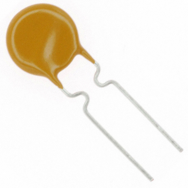
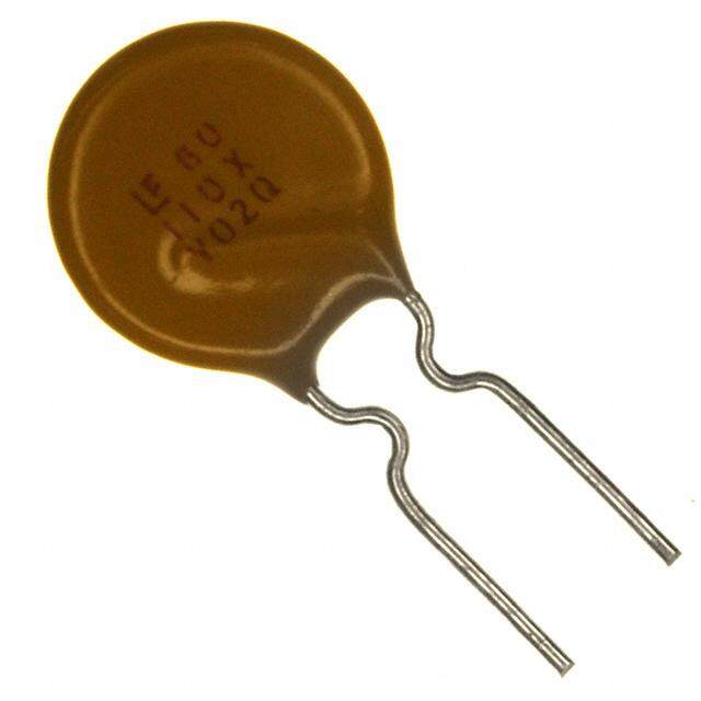
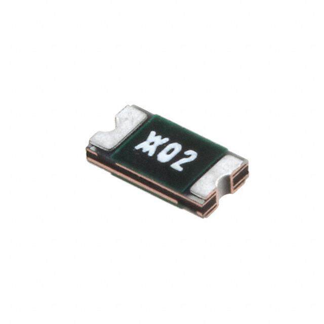
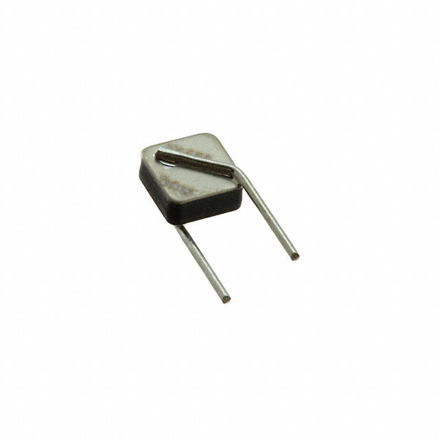
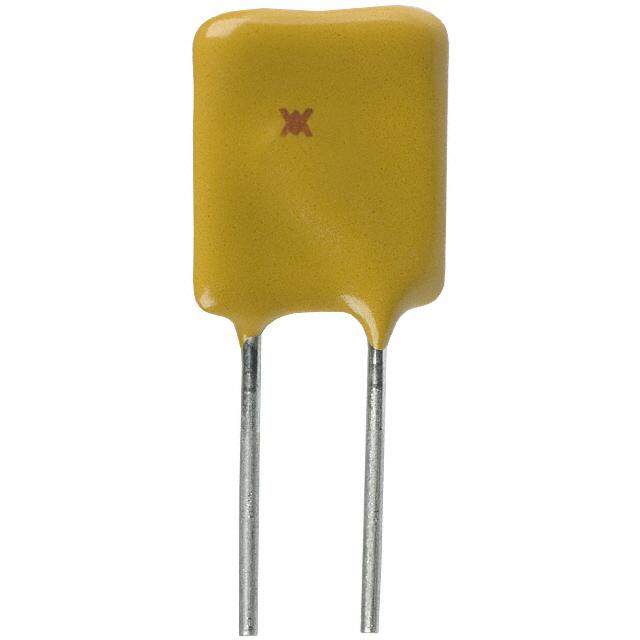
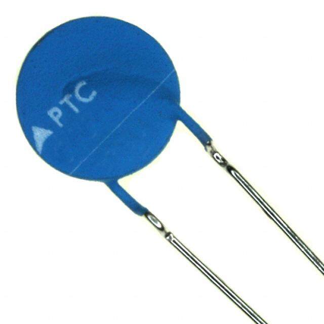
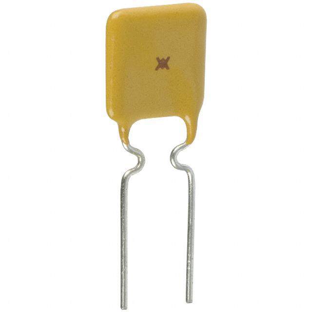
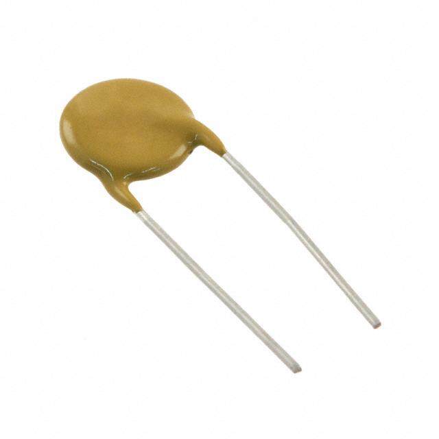
ICGOO电子元器件商城为您提供MF-R065-2由Bourns设计生产,在icgoo商城现货销售,并且可以通过原厂、代理商等渠道进行代购。 MF-R065-2价格参考。BournsMF-R065-2封装/规格:PTC 可复位保险丝, 聚合物 PTC 自恢复保险丝 60V 650mA Ih 通孔 径向,圆片式。您可以下载MF-R065-2参考资料、Datasheet数据手册功能说明书,资料中有MF-R065-2 详细功能的应用电路图电压和使用方法及教程。
Bourns Inc.的MF-R065-2型号PTC可复位保险丝是一种广泛应用于电子设备中的过流保护元件。PTC(正温度系数)热敏电阻具有在电流过大时迅速升温,阻值急剧增加的特点,从而限制电流,保护电路免受损坏。当故障排除后,它又能自动恢复到低阻状态,因此被称为“可复位保险丝”。

 应用场景:

1. 消费类电子产品:
   - 智能手机和平板电脑:用于USB接口、充电电路和电池管理系统中,防止因短路或过流导致的损坏。
   - 笔记本电脑和其他便携式设备:保护内部电源管理和数据传输接口,确保设备安全。

2. 家用电器:
   - 微波炉、洗衣机、空调等:用于电机驱动电路、电源输入端以及控制面板的保护,防止因电气故障引发的安全隐患。
   - 电风扇、吸尘器等小型家电:保护电机和电源线,避免因过载或短路引起的火灾风险。

3. 工业控制系统:
   - PLC(可编程逻辑控制器):保护输入输出模块,防止因外部干扰或误操作导致的系统故障。
   - 传感器和执行器:保护信号传输线路,确保数据传输的稳定性和可靠性。

4. 汽车电子:
   - 车载充电器、导航系统:用于USB接口、点烟器插座等部位,防止因不当使用或短路造成的损坏。
   - 电动车辆的电池管理系统:保护电池组和充电电路,确保车辆的安全运行。

5. 通信设备:
   - 路由器、交换机:用于电源输入和网络接口的保护,防止因雷击、静电放电等引起的损坏。
   - 基站设备:保护电源模块和通信接口,确保通信系统的稳定运行。

总之,MF-R065-2 PTC可复位保险丝凭借其可靠性和复位功能,在各类电子设备中提供了有效的过流保护,广泛应用于消费类电子产品、家用电器、工业控制系统、汽车电子和通信设备等领域。
| 参数 | 数值 |
| 产品目录 | |
| 描述 | FUSE PTC RESETTABLE |
| 产品分类 | |
| 品牌 | Bourns Inc. |
| 数据手册 | |
| 产品图片 |
|
| 产品型号 | MF-R065-2 |
| rohs | 无铅 / 符合限制有害物质指令(RoHS)规范要求 |
| RoHS指令信息 | |
| R(最小/最大值) | 0.270 ~ 0.480 欧姆 |
| 产品系列 | MF-R |
| 产品培训模块 | http://www.digikey.cn/PTM/IndividualPTM.page?site=cn&lang=zhs&ptm=5252http://www.digikey.cn/PTM/IndividualPTM.page?site=cn&lang=zhs&ptm=4768 |
| 产品目录绘图 |
|
| 其它名称 | MF-R065-2-ND |
| 包装 | 带卷 (TR) |
| 封装/外壳 | 径向,圆盘 |
| 标准包装 | 3,000 |
| 电压-最大值 | 60V |
| 电流-保持(Ih)(最大值) | 650mA |
| 电流-最大值 | 40A |
| 电流-跳闸(It) | 1.3A |
| 跳闸时间 | 5.3s |


- 商务部:美国ITC正式对集成电路等产品启动337调查
- 曝三星4nm工艺存在良率问题 高通将骁龙8 Gen1或转产台积电
- 太阳诱电将投资9.5亿元在常州建新厂生产MLCC 预计2023年完工
- 英特尔发布欧洲新工厂建设计划 深化IDM 2.0 战略
- 台积电先进制程称霸业界 有大客户加持明年业绩稳了
- 达到5530亿美元!SIA预计今年全球半导体销售额将创下新高
- 英特尔拟将自动驾驶子公司Mobileye上市 估值或超500亿美元
- 三星加码芯片和SET,合并消费电子和移动部门,撤换高东真等 CEO
- 三星电子宣布重大人事变动 还合并消费电子和移动部门
- 海关总署:前11个月进口集成电路产品价值2.52万亿元 增长14.8%


PDF Datasheet 数据手册内容提取
Features Applications n Radial Leaded Devices Almost anywhere there is a low voltage power n Cured, flame retardant epoxy polymer supply and a load to be protected, including: 7R118100T insulating material meets UL 94V-0 n Computers & peripherals requirements n General electronics n RoHS compliant* and halogen free** n Agency recognition: MF-R Series - PTC Resettable Fuses Electrical Characteristics Initial 1 Hour (R1) Max. Time Tripped Agency Ihold Itrip Post-Trip Power Resistance to Trip Recognition V max. I max. Resistance Dissipation Model Volts Amps Amperes Ohms Ohms Amperes Seconds Watts cUL TÜV at 23 °C at 23 °C at 23 °C at 23 °C at 23 °C at 23 °C Hold Trip Min. Max. Max. Typ. E174545 R50366745 MF-R005 60 40 0.05 0.10 7.3 11.1 22.0 0.5 5.0 0.22 3 3 MF-R010 60 40 0.10 0.20 2.50 4.50 7.50 0.5 4.0 0.38 3 3 MF-R017 60 40 0.17 0.34 2.00 3.20 8.00 0.85 3.0 0.48 3 3 MF-R020 60 40 0.20 0.40 1.50 2.84 4.40 1.0 2.2 0.40 3 3 MF-R025 60 40 0.25 0.50 1.00 1.95 3.00 1.25 2.5 0.45 3 3 MF-R030 60 40 0.30 0.60 0.76 1.36 2.10 1.5 3.0 0.50 3 3 MF-R040 60 40 0.40 0.80 0.52 0.86 1.29 2.0 3.8 0.55 3 3 MF-R050 60 40 0.50 1.00 0.41 0.77 1.17 2.5 4.0 0.75 3 3 MF-R065 60 40 0.65 1.30 0.27 0.48 0.72 3.25 5.3 0.90 3 3 MF-R075 60 40 0.75 1.50 0.18 0.40 0.60 3.75 6.3 0.90 3 3 MF-R090 60 40 0.90 1.80 0.14 0.31 0.47 4.5 7.2 1.00 3 3 MF-R090-0-9 30 40 0.90 1.80 0.07 0.12 0.22 4.5 5.9 0.60 3 3 MF-R110 30 40 1.10 2.20 0.10 0.18 0.27 5.5 6.6 0.70 3 3 MF-R135 30 40 1.35 2.70 0.065 0.115 0.17 6.75 7.3 0.80 3 3 MF-R160 30 40 1.60 3.20 0.055 0.105 0.15 8.0 8.0 0.90 3 3 MF-R185 30 40 1.85 3.70 0.040 0.07 0.11 9.25 8.7 1.00 3 3 MF-R250 30 40 2.50 5.00 0.025 0.048 0.07 12.5 10.3 1.20 3 3 MF-R250-0-10 30 40 2.50 5.00 0.025 0.048 0.07 12.5 10.3 1.20 3 3 MF-R300 30 40 3.00 6.00 0.020 0.05 0.08 15.0 10.8 2.00 3 3 MF-R400 30 40 4.00 8.00 0.010 0.03 0.05 20.0 12.7 2.50 3 3 MF-R500 30 40 5.00 10.00 0.010 0.03 0.05 25.0 14.5 3.00 3 3 MF-R600 30 40 6.00 12.00 0.005 0.02 0.04 30.0 16.0 3.50 3 3 MF-R700 30 40 7.00 14.00 0.005 0.02 0.03 35.0 17.5 3.80 3 3 MF-R800 30 40 8.00 16.00 0.005 0.02 0.03 40.0 18.8 4.00 3 3 MF-R900 30 40 9.00 18.00 0.005 0.01 0.02 40.0 20.0 4.20 3 3 MF-R1100 16 100 11.00 22.00 0.003 0.01 0.014 40.0 20.0 4.50 3 3 Environmental Characteristics Operating Temperature .........................................-40 °C to +85 °C Recommended Storage........................................+40 °C max. / 70 % R.H. max. Passive Aging .......................................................+85 °C, 1000 hours ...............................................±5 % typical resistance change Humidity Aging......................................................+85 °C, 85 % R.H. 1000 hours .............................±5 % typical resistance change Thermal Shock .....................................................-40 °C to +85 °C, 10 times ....................................±10 % typical resistance change Solvent Resistance ...............................................MIL-STD-202, Method 215 ...................................No change (marking still legible) Vibration ...............................................................MIL-STD-883C, Method 2007.1, ...........................No change (Rmin<R<R1max) Condition A Moisture Sensitivity Level (MSL) ........................See Note ESD Classification ................................................Class 6 (per AEC-Q200-2, HBM) Test Procedures and Requirements Test Test Conditions Accept/Reject Criteria Visual/Mech. .........................................................Verify dimensions and materials ...........................Per MF physical description Resistance ............................................................In still air @ 23 °C .................................................Rmin ≤ R ≤ Rmax Time to Trip ...........................................................5 times Ihold, Vmax, 23 °C ...................................T ≤ max. time to trip (seconds) Hold Current .........................................................30 min. at Ihold .....................................................No trip Trip Cycle Life .......................................................Vmax, Imax, 100 cycles ........................................No arcing or burning Trip Endurance .....................................................Vmax, 48 hours .....................................................No arcing or burning Solderability ..........................................................245 °C ±5 °C, 5 seconds ......................................95 % min. coverage WARNING Cancer and Reproductive Harm - www.P65Warnings.ca.gov * RoHS Directive 2015/863, Mar 31, 2015 and Annex. ** Bourns follows the prevailing definition of “halogen free” in the industry. Bourns considers a product to be “halogen free” if (a) the Bromine (Br) content is 900 ppm or less; (b) the Chlorine (Cl) content is 900 ppm or less; and (c) the total Bromine (Br) and Chlorine (Cl) content is 1500 ppm or less. Specifications are subject to change without notice. Users should verify actual device performance in their specific applications. The products described herein and this document are subject to specific disclaimers as set forth on the last page of this document, and at www.bourns.com/legal/disclaimer.pdf.
Additional Features n Bulk packaging, tape and reel and Ammo-Pak available on most models MF-R Series - PTC Resettable Fuses Product Dimensions (see next page for outline drawing) Model A B C D E Physical Characteristics Max. Max. Nom. Tol. ± Min. Max. Style Lead Dia. Material 8.0 8.3 5.1 0.7 7.6 3.1 0.405 MF-R005 4 Sn/NiCu (0.315) (0.327) (0.201) (0.028) (0.299) (0.122) (0.016) 7.4 12.7 5.1 0.7 7.6 3.1 0.51 MF-R010 1 Sn/NiCu (0.291) (0.5) (0.201) (0.028) (0.299) (0.122) (0.020) 7.4 12.7 5.1 0.7 7.6 3.1 0.51 MF-R017 1 Sn/CuFe (0.291) (0.5) (0.201) (0.028) (0.299) (0.122) (0.020) 7.4 12.7 5.1 0.7 7.6 3.1 0.51 MF-R020 1 Sn/CuFe (0.291) (0.5) (0.201) (0.028) (0.299) (0.122) (0.020) 7.4 12.7 5.1 0.7 7.6 3.1 0.51 MF-R025 1 Sn/CuFe (0.291) (0.5) (0.201) (0.028) (0.299) (0.122) (0.020) 7.4 13.4 5.1 0.7 7.6 3.1 0.51 MF-R030 1 Sn/CuFe (0.291) (0.528) (0.201) (0.028) (0.299) (0.122) (0.020) 7.4 13.7 5.1 0.7 7.6 3.1 0.51 MF-R040 1 Sn/CuFe (0.291) (0.539) (0.201) (0.028) (0.299) (0.122) (0.020) 7.9 13.7 5.1 0.7 7.6 3.1 0.51 MF-R050 1 Sn/Cu (0.311) (0.539) (0.201) (0.028) (0.299) (0.122) (0.020) 9.7 15.2 5.1 0.7 7.6 3.1 0.51 MF-R065 1 Sn/Cu (0.382) (0.598) (0.201) (0.028) (0.299) (0.122) (0.020) 10.4 16.0 5.1 0.7 7.6 3.1 0.51 MF-R075 1 Sn/Cu (0.409) (0.630) (0.201) (0.028) (0.299) (0.122) (0.020) 11.7 16.7 5.1 0.7 7.6 3.1 0.51 MF-R090 1 Sn/Cu (0.461) (0.657) (0.201) (0.028) (0.299) (0.122) (0.020) 7.4 12.2 5.1 0.7 7.6 3.0 0.51 MF-R090-0-9 3 Sn/CuFe (0.291) (0.480) (0.201) (0.028) (0.299) (0.118) (0.020) 8.9 14.0 5.1 0.7 7.6 3.0 0.51 MF-R110 1 Sn/Cu (0.350) (0.551) (0.201) (0.028) (0.299) (0.118) (0.020) 8.9 18.9 5.1 0.7 7.6 3.0 0.51 MF-R135 1 Sn/Cu (0.350) (0.744) (0.201) (0.028) (0.299) (0.118) (0.020) 10.2 16.8 5.1 0.7 7.6 3.0 0.51 MF-R160 1 Sn/Cu (0.402) (0.661) (0.201) (0.028) (0.299) (0.118) (0.020) 12.0 18.4 5.1 0.7 7.6 3.0 0.51 MF-R185 1 Sn/Cu (0.472) (0.724) (0.201) (0.028) (0.299) (0.118) (0.020) 12.0 18.3 5.1 0.7 7.6 3.0 0.81 MF-R250 2 Sn/Cu (0.472) (0.720) (0.201) (0.028) (0.299) (0.118) (0.032) 12.0 18.3 5.1 0.7 7.6 3.0 0.51 MF-R250-0-10 3 Sn/CuFe (0.472) (0.720) (0.201) (0.028) (0.299) (0.118) (0.020) 12.0 18.3 5.1 0.7 7.6 3.0 0.81 MF-R300 2 Sn/Cu (0.472) (0.720) (0.201) (0.028) (0.299) (0.118) (0.032) 14.4 24.8 5.1 0.7 7.6 3.0 0.81 MF-R400 2 Sn/Cu (0.567) (0.976) (0.201) (0.028) (0.299) (0.118) (0.032) 17.4 24.9 10.2 0.7 7.6 3.0 0.81 MF-R500 2 Sn/Cu (0.685) (0.980) (0.402) (0.028) (0.299) (0.118) (0.032) 19.3 31.9 10.2 0.7 7.6 3.0 0.81 MF-R600 2 Sn/Cu (0.760) (1.256) (0.402) (0.028) (0.299) (0.118) (0.032) 22.1 29.8 10.2 0.7 7.6 3.0 0.81 MF-R700 2 Sn/Cu (0.870) (1.173) (0.402) (0.028) (0.299) (0.118) (0.032) 24.2 32.9 10.2 0.7 7.6 3.0 0.81 MF-R800 2 Sn/Cu (0.953) (1.295) (0.402) (0.028) (0.299) (0.118) (0.032) 24.2 32.9 10.2 0.7 7.6 3.0 0.81 MF-R900 2 Sn/Cu (0.953) (1.295) (0.402) (0.028) (0.299) (0.118) (0.032) 24.2 32.9 10.2 0.7 7.6 3.0 0.81 MF-R1100 2 Sn/Cu (0.953) (1.295) (0.402) (0.028) (0.299) (0.118) (0.032) MM DIMENSIONS: (INCHES) Specifications are subject to change without notice. Users should verify actual device performance in their specific applications. The products described herein and this document are subject to specific disclaimers as set forth on the last page of this document, and at www.bourns.com/legal/disclaimer.pdf.
MF-R Series - PTC Resettable Fuses Product Dimensions (see previous page for dimensions) Style 1 Style 2 Style 3 Style 4 A E A E A E A E B B B B D C D D D C C C NOTE: Kinked lead option is NOTE: Also available with available for board standoff. straight leads. Contact Contact factory for details. factory for details. Thermal Derating Chart - Ihold / Itrip (Amps) Ambient Operating Temperature Model -40 ºC -20 ºC 0 ºC 23 ºC 40 ºC 50 ºC 60 ºC 70 ºC 85 ºC MF-R005 0.08 / 0.16 0.07 / 0.14 0.06 / 0.12 0.05 / 0.10 0.04 / 0.08 0.04 / 0.08 0.03 / 0.07 0.03 / 0.07 0.02 / 0.05 MF-R010 0.16 / 0.32 0.14 / 0.28 0.12 / 0.24 0.10 / 0.20 0.08 / 0.16 0.07 / 0.14 0.06 / 0.12 0.05 / 0.10 0.04 / 0.08 MF-R017 0.26 / 0.52 0.23 / 0.46 0.20 / 0.40 0.17 / 0.34 0.14 / 0.28 0.12 / 0.24 0.11 / 0.22 0.09 / 0.18 0.07 / 0.14 MF-R020 0.31 / 0.62 0.27 / 0.54 0.24 / 0.48 0.20 / 0.40 0.16 / 0.32 0.14 / 0.28 0.13 / 0.26 0.11 / 0.22 0.08 / 0.16 MF-R025 0.39 / 0.78 0.34 / 0.68 0.30 / 0.60 0.25 / 0.50 0.20 / 0.40 0.18 / 0.36 0.16 / 0.32 0.14 / 0.28 0.10 / 0.20 MF-R030 0.47 / 0.94 0.41 / 0.82 0.36 / 0.72 0.30 / 0.60 0.24 / 0.48 0.22 / 0.44 0.19 / 0.38 0.16 / 0.32 0.12 / 0.24 MF-R040 0.62 / 1.24 0.54 / 1.08 0.48 / 0.96 0.40 / 0.80 0.32 / 0.64 0.29 / 0.58 0.25 / 0.50 0.22 / 0.44 0.16 / 0.32 MF-R050 0.78 / 1.56 0.68 / 1.36 0.60 / 1.20 0.50 / 1.00 0.41 / 0.82 0.36 / 0.72 0.32 / 0.64 0.27 / 0.54 0.20 / 0.40 MF-R065 1.01 / 2.02 0.88 / 1.76 0.77 / 1.54 0.65 / 1.30 0.53 / 1.06 0.47 / 0.94 0.41 / 0.82 0.35 / 0.70 0.26 / 0.52 MF-R075 1.16 / 2.32 1.02 / 2.04 0.89 / 1.78 0.75 / 1.50 0.61 / 1.22 0.54 / 1.08 0.47 / 0.94 0.41 / 0.82 0.30 / 0.60 MF-R090 1.40 / 2.80 1.22 / 2.44 1.07 / 2.14 0.90 / 1.80 0.73 / 1.46 0.65 / 1.30 0.57 / 1.14 0.49 / 0.98 0.36 / 0.72 MF-R090-0-9 1.40 / 2.80 1.22 / 2.44 1.07 / 2.14 0.90 / 1.80 0.73 / 1.46 0.65 / 1.30 0.57 / 1.14 0.49 / 0.98 0.36 / 0.72 MF-R110 1.60 / 3.20 1.43 / 2.86 1.27 / 2.54 1.10 / 2.20 0.91 / 1.82 0.85 / 1.70 0.75 / 1.50 0.67 / 1.34 0.57 / 1.14 MF-R135 1.96 / 3.92 1.76 / 3.52 1.55 / 3.10 1.35 / 2.70 1.12 / 2.24 1.04 / 2.08 0.92 / 1.84 0.82 / 1.64 0.70 / 1.40 MF-R160 2.32 / 4.64 2.08 / 4.16 1.84 / 3.68 1.60 / 3.20 1.33 / 2.66 1.23 / 2.46 1.09 / 2.18 0.98 / 1.96 0.83 / 1.66 MF-R185 2.68 / 5.36 2.41 / 4.82 2.13 / 4.26 1.85 / 3.70 1.54 / 3.08 1.42 / 2.84 1.26 / 2.52 1.13 / 2.26 0.96 / 1.92 MF-R250 3.63 / 7.26 3.25 / 6.50 2.88 / 5.76 2.50 / 5.00 2.08 / 4.16 1.93 / 3.86 1.70 / 3.40 1.53 / 3.06 1.30 / 2.60 MF-R250-0-10 3.63 / 7.26 3.25 / 6.50 2.88 / 5.76 2.50 / 5.00 2.08 / 4.16 1.93 / 3.86 1.70 / 3.40 1.53 / 3.06 1.30 / 2.60 MF-R300 4.35 / 8.70 3.90 / 7.80 3.45 / 6.90 3.00 / 6.00 2.49 / 4.98 2.31 / 4.62 2.04 / 4.08 1.83 / 3.66 1.56 / 3.12 MF-R400 5.80 / 11.6 5.20 / 10.4 4.60 / 9.20 4.00 / 8.00 3.32 / 6.64 3.08 / 6.16 2.72 / 5.44 2.44 / 4.88 2.08 / 4.16 MF-R500 7.25 / 14.5 6.50 / 13.0 5.75 / 11.5 5.00 / 10.0 4.15 / 8.30 3.85 / 7.70 3.40 / 6.80 3.05 / 6.10 2.60 / 5.20 MF-R600 8.70 / 17.4 7.80 / 15.6 6.90 / 13.8 6.00 / 12.0 4.98 / 9.96 4.62 / 9.24 4.08 / 8.16 3.66 / 7.32 3.12 / 6.24 MF-R700 10.1 / 20.3 9.10 / 18.2 8.05 / 16.1 7.00 / 14.0 5.81 / 11.6 5.39 / 10.7 4.76 / 9.52 4.27 / 9.44 3.64 / 7.28 MF-R800 11.6 / 23.2 10.4 / 20.8 9.20 / 18.4 8.00 / 16.0 6.64 / 13.2 6.16 / 12.3 5.44 / 10.8 4.88 / 9.76 4.16 / 8.32 MF-R900 13.0 / 26.1 11.7 / 23.4 10.3 / 20.7 9.00 / 18.0 7.47 / 14.9 6.93 / 12.7 6.12 / 12.2 5.49 / 10.9 4.68 / 9.36 MF-R1100 16.1 / 32.0 14.6 / 29.2 13.1 / 26.2 11.0 / 22.1 9.40 / 18.4 8.80 / 17.6 7.80 / 15.6 6.90 / 13.8 5.20 / 10.4 Specifications are subject to change without notice. Users should verify actual device performance in their specific applications. The products described herein and this document are subject to specific disclaimers as set forth on the last page of this document, and at www.bourns.com/legal/disclaimer.pdf.
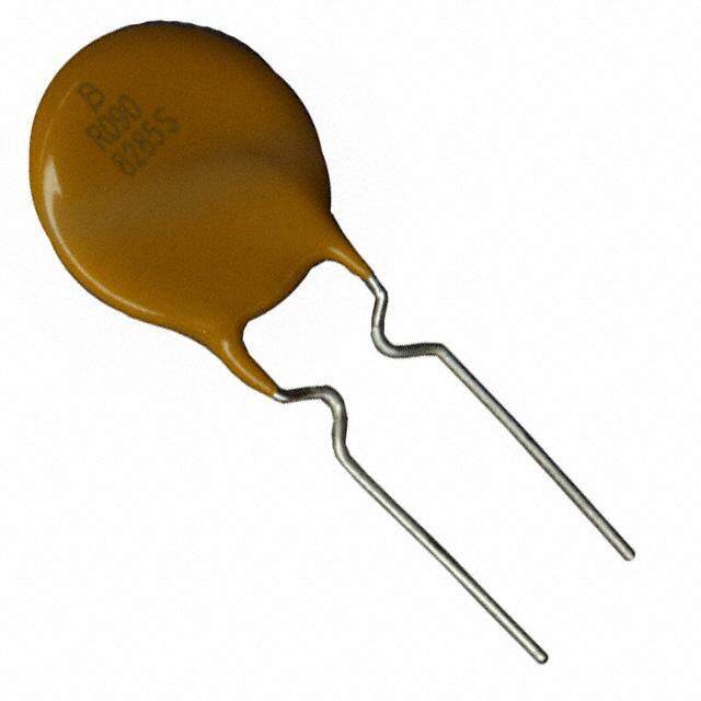
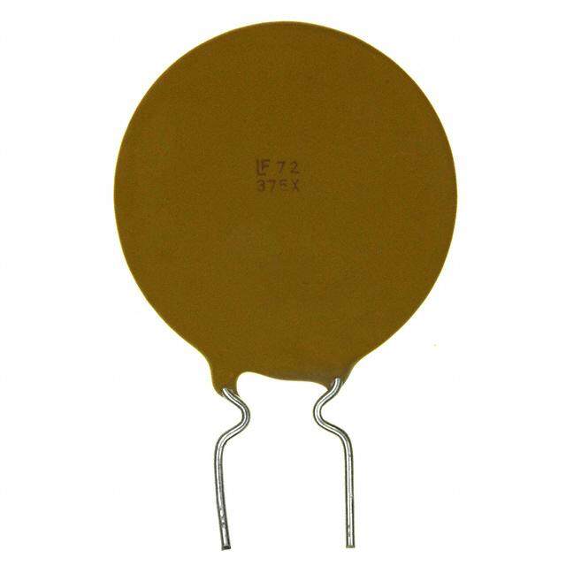
MF-R Series - PTC Resettable Fuses Typical Time to Trip at 23 ºC How to Order MF - R 110 - 0 - 14 MF-R005MF-R010MF-R01M7F-R020MF-R02M5F-R03M0F-R040MF-R05M0F-R065MF-R075MF-R090 MPruoldtifuucste D® e signator Series R = Radial Leaded Component Hold Current, Ihold 005-1100 (0.05 Amps - 11.0 Amps) Packaging Options - __ = Bulk Packaging without part number suffix option 100 - 0 = Bulk Packaging with part number suffix option ) ds - 2 = Tape and Reel on 10 - AP = Ammo-Pak* c e Part Number Suffix Option S ( - 14 = Kinked leads where straight leads p 1 are standard ri me to t 0.1 -- 1979 == SaRrtoeraH siSgtah Cnt doleamarpddlsia wnhcyere kinked leads Ti As of date code April 1, 2005 all MF-R models are RoHS compliant. The suffix “-99” was originally provided 0.01 to help customers distinguish between RoHS compliant and non-RoHS com- pliant products, but the -99 suffix option is no longer necessary. The -99 0.001 suffix option will no longer be available starting January 1, 2020. See Note 0.1 1 10 100 for more details. Fault Current (Amps) *Packaged per EIA-468 MF- R-009-09MF-R110MF-R135MF-R160MF-R18M5F-R22550,0-0-10MF-R30M0F-R400MF-R50M0F-R60M0F-R700MF-R800MF-R900MF-R1100 ReTpyrpePiscAeRanTl tPs atortt aMl acorknitnegn:t .M LFa-yRo0u0t 5m -a Ry 0v2a5ry. IDENTIFICATION 025 MANUFACTURER'S 7A S MANUFACTURING TRADEMARK LOCATION: S = CHINA DATE CODE: 100 WEEK 1 OF 2017 = 7A (YEAR & WEEK) WEEK 27 OF 2017 = A7 (WEEK & YEAR) ) s d n 10 o Typical Part Marking: MF-R030 - R1100 c e S Represents total content. Layout may vary. ( p 1 ri MANUFACTURER'S o t PART TRADEMARK me t 0.1 IDENTIFICATION R250 MANUFACTURING Ti 7180 S LTO =C TAATIIWONA:N S = CHINA 0.01 DATE CODE: FIRST DIGIT = LAST DIGIT OF YEAR; NEXT THREE DIGITS = DAY OF YEAR 0.001 1 10 100 Fault Current (Amps) Specifications are subject to change without notice. Users should verify actual device performance in their specific applications. The products described herein and this document are subject to specific disclaimers as set forth on the last page of this document, and at www.bourns.com/legal/disclaimer.pdf.
MF-R Series - PTC Resettable Fuses Packaging Quantity Packaging options: BULK: All models = 500 pcs. per bag TAPE & REEL: MF-R005 ~ MF-R160 12.7 mm device pitch = 3000 pcs. per reel MF-R185 ~ MF-R400 25.4 mm device pitch = 1500 pcs. per reel MF-R500 ~ MF-R1100 25.4 mm device pitch = 1000 pcs. per reel AMMO-PACK: MF-R005 ~ MF-R160 12.7 mm device pitch = 2000 pcs. per pack MF-R185 ~ MF-R400 25.4 mm device pitch = 1000 pcs. per pack MF-R500 ~ MF-R1100 25.4 mm device pitch = 500 pcs. per pack MF-R SERIES, REV. AI, 05/19 Specifications are subject to change without notice. Users should verify actual device performance in their specific applications. The products described herein and this document are subject to specific disclaimers as set forth on the last page of this document, and at www.bourns.com/legal/disclaimer.pdf.
MF-R Series Tape and Reel Specifications Devices taped using EIA-468/IEC 60286-2 standards. See table below and Figures 1~4 for details. IEC EIA Dimensions Dimension Description Mark Mark Dimensions Tolerance 18 -0.5/+1.0 Carrier tape width W W (.709) (-0.02/+.039) 5 H old down tape width W 0 W 0 (.197) min. Hold down tape No protrusion 3 A dhesive tape position W 2 W 2 (.118) max. 9 -0.5/+0.75 S procket hole position W 1 W 1 (.354) (-0.02/+0.03) 4 ±0.2 S procket hole diameter D 0 D 0 (.157) (±.0078) 18 ~ 20 Height to seating plane (straight lead) H H (.709 ~ .787) 16 ±0.5 H eight to seating plane (formed lead) H 0 H 0 (.63) (±.02) 38.5 O verall height above abscissa H 1 H 1 (1.516) max. 1.0 L ead protrusion L L1 (.039) max. 11 Cutout Length L max. (.433) l Protrusion beyond hold-down tape, l2 Not specified 12.7 ±0.3 Sprocket hole pitch P 0 P 0 (0.5) (±.012) 12.7 ±0.3 Device pitch: MF-R005 ~ MF-R160 P P (0.5) (±.012) 25.4 ±0.6 Device pitch: MF-R185 ~ MF-R1100 P P (1.0) (±.024) ±1 Pitch tolerance 20 consecutive (±.039) 0.9 Composite tape thickness t t max. (.035) 2.0 O verall tape and lead thickness: MF-R005 ~ MF-R185 t1 t1 (0.079) max. 2.3 O verall tape and lead thickness: MF-R250 ~ MF-R1100 t1 t1 (0.091) max. ±0.3 Splice sprocket hole alignment 0 (±.012) F ront-to-back deviation Δ h Δ h 0 (±±.10.309 ) S ide-to-side deviation Δ p Δ p 0 (±±.10.531 ) MM DIMENSIONS: (INCHES) — Continued on next page — Specifications are subject to change without notice. Users should verify actual device performance in their specific applications. The products described herein and this document are subject to specific legal disclaimers as set forth on the last page of this document, and at www.bourns.com/docs/legal/disclaimer.pdf.
MF-R Series Tape and Reel Specifications IEC EIA Dimensions Dimension Description Mark Mark Dimensions Tolerance 3.81 ±0.7 Ordinate to adjacent component lead P 1 P 1 (0.150) (±0.028) 5.08 +0.6/-0.2 Lead spacing: MF-R005 ~ MF-R400 F F (0.2) (+0.024/-0.008) 10.2 +0.6/-0.2 Lead spacing: MF-R500 ~ MF-R1100 F F (0.4) (+0.024/-0.008) 62.0 R eel width including flanges and hub W 4 w 2 (2.44) max. Dimension between flanges (measured at hub) W 3 w 1 allow proper reeling and unreeling 370.0 Reel diameter A a max. (14.57) 4.75 ±3.25 Space between flanges (at hub, excluding device) (.187) (±.128) 26.0 ±12.0 Arbor hole diameter C c (1.024) (±.472) 80 Core diameter N n min. (3.15) 62 372 372 Box dimensions max. (2.44) (14.6) (14.6) Consecutive missing places 3 max. h h p p Empty places per reel Not specified Taped Component h h p p Reference plane Dimensions per EIA Mark - Figure 1 H1 P1 F W2 H1 H Applies to Models: Reference Hplane MF-R500 HL1 P1 A B FW0 W2 0 W1 W H1 H MF-R600 H MF-R700 L A B W 0 W1 0 W MF-R800 I2 L1 P0 D0 t1 Cross section A - B t MF-R900 User direction of feed MF-R1100 I2 L1 P0 D0 t1 Cross section A - B t User direction of feed Reel Dimensions per EIA Mark - Reel Figure 2 n Upper side Applies to Models: Reel Tape User MF-R500 a direction DIMENSIONS: MM n of Upper side (INCHES) MF-R600 feed LowTear pseide User MF-R700 c a direction MF-R800 of feed Lower side MF-R900 w1 c MF-R1100 w2 MM DIMENSIONS: (INCHES) w 1 Specifications are subject to change without notice. Users should verify actual device performancew i2n their specific applications. The products described herein and this document are subject to specific legal disclaimers as set forth on the last page of this document, and at www.bourns.com/docs/legal/disclaimer.pdf.
h h p p MF-R Series Tape and Reel Specifications Reference plane Taped Component Dimensions - H1 P1 F W2 H1 H per EIA Mark - h h H p p Figure 3 L A B 0 W W 1 0 W Applies to Models: Reference plane MF-R005 ~ MF-R400 H1 P0 P1 DF0 W2 User direction of feed H H1 H L A B W 0 Wt11 Cross section A - B t 0 W P0 D0 User direction of feed t Cross section A - B t 1 Reel Dimensions - per EIA Mark - Figure 4 Reel Applies to Models: Upper side MF-R005 ~ MF-R400 n Tape User a direction of feed Reel c Lower side Upper side n Tape w1 User w2 a direction of MM DIMENSIONS: feed (INCHES) c Lower side w 1 w 2 Specifications are subject to change without notice. Users should verify actual device performance in their specific applications. The products described herein and this document are subject to specific legal disclaimers as set forth on the last page of this document, and at www.bourns.com/docs/legal/disclaimer.pdf.
3B3o1u2rn -s ®2 Mmumlti fSuMseD® TPrPimTCm Rinegse Pttoatbelnet Fioumseester Application Notice • Users are responsible for independent and adequate evaluation of Bourns® Multifuse® Polymer PTC devices in the user’s application, including the PPTC device characteristics stated in the applicable data sheet. • Polymer PTC devices must not be allowed to operate beyond their stated maximum ratings. Operation in excess of such maximum ratings could result in damage to the PTC device and possibly lead to electrical arcing and/or fire. Circuits with inductance may generate a voltage above the rated voltage of the polymer PTC device and should be thoroughly evaluated within the user’s application during the PTC selection and qualification process. • Polymer PTC devices are intended to protect against adverse effects of temporary overcurrent or overtemperature conditions up to rated limits and are not intended to serve as protective devices where overcurrent or overvoltage conditions are expected to be repetitive or prolonged. • In normal operation, polymer PTC devices experience thermal expansion under fault conditions. Thus, a polymer PTC device must be protected against mechanical stress, and must be given adequate clearance within the user’s application to accommodate such thermal expansion. Rigid potting materials or fixed housings or coverings that do not provide adequate clearance should be thoroughly examined and tested by the user, as they may result in the malfunction of polymer PTC devices if the thermal expansion is inhibited. • Exposure to lubricants, silicon-based oils, solvents, gels, electrolytes, acids, and other related or similar materials may adversely affect the performance of polymer PTC devices. • Aggressive solvents may adversely affect the performance of polymer PTC devices. Conformal coating, encapsulating, potting, molding, and sealing materials may contain aggressive solvents including but not limited to xylene and toluene, which are known to cause adverse effects on the performance of polymer PTCs. Such aggressive solvents must be thoroughly cured or baked to ensure their complete removal from polymer PTCs to minimize the possible adverse effect on the device. • Recommended storage conditions should be followed at all times. Such conditions can be found on the applicable data sheet and on the Multifuse® Polymer PTC Moisture/Reflow Sensitivity Classification (MSL) note: https://www.bourns.com/docs/RoHS-MSL/msl_mf.pdf MFAN 12/18 Specifications are subject to change without notice. Users should verify actual device performance in their specific applications. The products described herein and this document are subject to specific legal disclaimers as set forth on the last page of this document, and at www.bourns.com/docs/legal/disclaimer.pdf.
Legal Disclaimer Notice This legal disclaimer applies to purchasers and users of Bourns® products manufactured by or on behalf of Bourns, Inc. and its affiliates (collectively, “Bourns”). Unless otherwise expressly indicated in writing, Bourns® products and data sheets relating thereto are subject to change without notice. Users should check for and obtain the latest relevant information and verify that such information is current and complete before placing orders for Bourns® products. The characteristics and parameters of a Bourns® product set forth in its data sheet are based on laboratory conditions, and statements regarding the suitability of products for certain types of applications are based on Bourns’ knowledge of typical requirements in generic applications. The characteristics and parameters of a Bourns® product in a user application may vary from the data sheet characteristics and parameters due to (i) the combination of the Bourns® product with other components in the user’s application, or (ii) the environment of the user application itself. The characteristics and parameters of a Bourns® product also can and do vary in different applications and actual performance may vary over time. Users should always verify the actual performance of the Bourns® product in their specific devices and applications, and make their own independent judgments regarding the amount of additional test margin to design into their device or application to compensate for differences between laboratory and real world conditions. Unless Bourns has explicitly designated an individual Bourns® product as meeting the requirements of a particular industry standard (e.g., ISO/TS 16949) or a particular qualification (e.g., UL listed or recognized), Bourns is not responsible for any failure of an individual Bourns® product to meet the requirements of such industry standard or particular qualification. Users of Bourns® products are responsible for ensuring compliance with safety-related requirements and standards applicable to their devices or applications. Bourns® products are not recommended, authorized or intended for use in nuclear, lifesaving, life-critical or life-sustaining ap- plications, nor in any other applications where failure or malfunction may result in personal injury, death, or severe property or environmental damage. Unless expressly and specifically approved in writing by two authorized Bourns representatives on a case-by-case basis, use of any Bourns® products in such unauthorized applications might not be safe and thus is at the user’s sole risk. Life-critical applications include devices identified by the U.S. Food and Drug Administration as Class III devices and generally equivalent classifications outside of the United States. Bourns expressly identifies those Bourns® standard products that are suitable for use in automotive applications on such products’ data sheets in the section entitled “Applications.” Unless expressly and specifically approved in writing by two authorized Bourns representatives on a case-by-case basis, use of any other Bourns® standard products in an automotive application might not be safe and thus is not recommended, authorized or intended and is at the user’s sole risk. If Bourns expressly identifies a sub-category of automotive application in the data sheet for its standard products (such as infotainment or lighting), such identification means that Bourns has reviewed its standard product and has determined that if such Bourns® standard product is considered for potential use in automotive applications, it should only be used in such sub-category of automotive applications. Any reference to Bourns® standard product in the data sheet as compliant with the AEC-Q standard or “automotive grade” does not by itself mean that Bourns has approved such product for use in an automotive application. Bourns® standard products are not tested to comply with United States Federal Aviation Administration standards generally or any other generally equivalent governmental organization standard applicable to products designed or manufactured for use in aircraft or space applications. Bourns expressly identifies Bourns® standard products that are suitable for use in aircraft or space applications on such products’ data sheets in the section entitled “Applications.” Unless expressly and specifically approved in writing by two authorized Bourns representatives on a case-by-case basis, use of any other Bourns® standard product in an aircraft or space application might not be safe and thus is not recommended, authorized or intended and is at the user’s sole risk. The use and level of testing applicable to Bourns® custom products shall be negotiated on a case-by-case basis by Bourns and the user for which such Bourns® custom products are specially designed. Absent a written agreement between Bourns and the user regarding the use and level of such testing, the above provisions applicable to Bourns® standard products shall also apply to such Bourns® custom products. Users shall not sell, transfer, export or re-export any Bourns® products or technology for use in activities which involve the design, development, production, use or stockpiling of nuclear, chemical or biological weapons or missiles, nor shall they use Bourns® products or technology in any facility which engages in activities relating to such devices. The foregoing restrictions apply to all uses and applications that violate national or international prohibitions, including embargos or international regulations. Further, Bourns® products and Bourns technology and technical data may not under any circumstance be exported or re-exported to countries subject to international sanctions or embargoes. Bourns® products may not, without prior authorization from Bourns and/or the U.S. Government, be resold, transferred, or re-exported to any party not eligible to receive U.S. commodities, software, and technical data. To the maximum extent permitted by applicable law, Bourns disclaims (i) any and all liability for special, punitive, consequential, incidental or indirect damages or lost revenues or lost profits, and (ii) any and all implied warranties, including implied warranties of fitness for particular purpose, non-infringement and merchantability. For your convenience, copies of this Legal Disclaimer Notice with German, Spanish, Japanese, Traditional Chinese and Simplified Chinese bilingual versions are available at: Web Page: http://www.bourns.com/legal/disclaimers-terms-and-policies PDF: http://www.bourns.com/docs/Legal/disclaimer.pdf C1753 05/17/18R