ICGOO在线商城 > 电路保护 > PTC 可复位保险丝 > MF-PSHT010X-2

 Datasheet下载
- 型号: MF-PSHT010X-2
- 制造商: Bourns
- 库位|库存: xxxx|xxxx
- 要求:
| 数量阶梯 | 香港交货 | 国内含税 |
| +xxxx | $xxxx | ¥xxxx |
查看当月历史价格
查看今年历史价格
MF-PSHT010X-2产品简介:
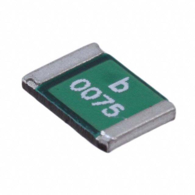
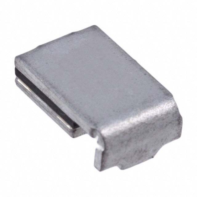
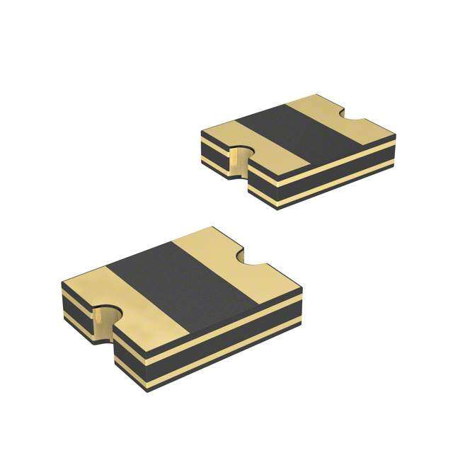
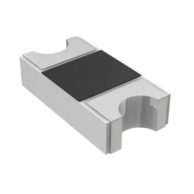
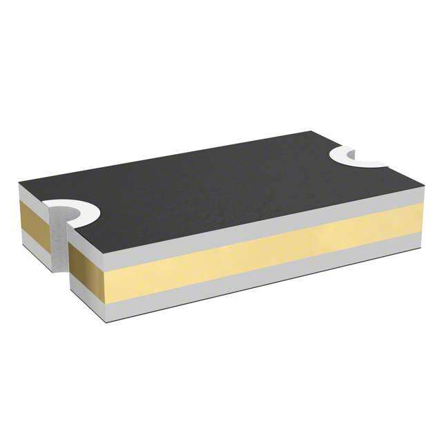
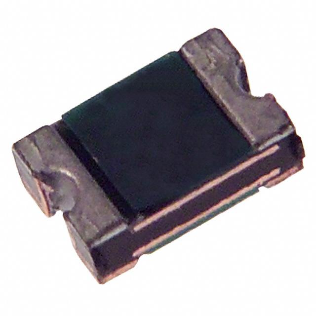
ICGOO电子元器件商城为您提供MF-PSHT010X-2由Bourns设计生产,在icgoo商城现货销售,并且可以通过原厂、代理商等渠道进行代购。 MF-PSHT010X-2价格参考。BournsMF-PSHT010X-2封装/规格:PTC 可复位保险丝, 聚合物 PTC 自恢复保险丝 16V 100mA Ih 表面贴装 0805(2012 公制),凹陷。您可以下载MF-PSHT010X-2参考资料、Datasheet数据手册功能说明书,资料中有MF-PSHT010X-2 详细功能的应用电路图电压和使用方法及教程。
Bourns Inc. 的 PTC 可复位保险丝型号 MF-PSHT010X-2 主要用于电路中提供过流和过温保护。该器件在检测到异常电流时会自动切换至高阻态,从而限制电流流动,并在故障排除后自动恢复,无需更换元件。

其主要应用场景包括:

1. 消费电子产品:如智能手机、平板电脑、笔记本电脑等设备的电源管理电路中,防止因短路或负载过大导致损坏。
2. 工业控制系统:用于PLC、传感器模块、继电器驱动电路中,提升系统可靠性。
3. 通信设备:适用于路由器、交换机、基站模块等,对电源端口和信号线路进行保护。
4. 汽车电子:可用于车载充电器、控制模块、ECU单元中,增强电路稳定性与安全性。
5. LED照明系统:保护LED驱动电路免受过流损害,延长灯具寿命。

该器件具备体积小、响应快、可自动复位等特点,适合需要频繁通断或难以维护的应用场合。
| 参数 | 数值 |
| 产品目录 | |
| 描述 | FUSE PTC RESETTABLE SMD 0805可复位保险丝—PPTC 0.10A 16V 1ohm HI Temp Case 0805 |
| 产品分类 | |
| 品牌 | Bourns |
| 产品手册 | |
| 产品图片 |
|
| rohs | 符合RoHS无铅 / 符合限制有害物质指令(RoHS)规范要求 |
| 产品系列 | Bourns MF-PSHT010X-2MF-PSHT |
| mouser_ship_limit | 该产品可能需要其他文件才能进口到中国。 |
| 数据手册 | |
| 产品型号 | MF-PSHT010X-2 |
| R(最小/最大值) | 1.000 ~ 7.500 欧姆 |
| 产品种类 | 可复位保险丝—PPTC |
| 保持电流 | 0.1 A |
| 其它名称 | MF-PSHT010X-2DKR |
| 包装 | Digi-Reel® |
| 商标 | Bourns |
| 商标名 | Multifuse |
| 安装风格 | SMD/SMT |
| 封装 | Reel |
| 封装/外壳 | 0805(2012 公制),凹陷 |
| 尺寸 | 2.3 mm L x 0.8 mm W x 1.5 mm H |
| 工作温度范围 | - 40 C to + 125 C |
| 工厂包装数量 | 3000 |
| 最大电压 | 16 V |
| 标准包装 | 1 |
| 电压-最大值 | 16V |
| 电流-保持(Ih)(最大值) | 100mA |
| 电流-最大值 | 40A |
| 电流-跳闸(It) | 600mA |
| 电阻 | 7.5 Ohms |
| 端接类型 | SMD/SMT |
| 类型 | PTC Resettable Fuses |
| 系列 | MF-PSHT |
| 跳闸时间 | 1.5s |
| 跳闸电流 | 0.6 A |
| 额定电流—最大值 | 40 A |


- 商务部:美国ITC正式对集成电路等产品启动337调查
- 曝三星4nm工艺存在良率问题 高通将骁龙8 Gen1或转产台积电
- 太阳诱电将投资9.5亿元在常州建新厂生产MLCC 预计2023年完工
- 英特尔发布欧洲新工厂建设计划 深化IDM 2.0 战略
- 台积电先进制程称霸业界 有大客户加持明年业绩稳了
- 达到5530亿美元!SIA预计今年全球半导体销售额将创下新高
- 英特尔拟将自动驾驶子公司Mobileye上市 估值或超500亿美元
- 三星加码芯片和SET,合并消费电子和移动部门,撤换高东真等 CEO
- 三星电子宣布重大人事变动 还合并消费电子和移动部门
- 海关总署:前11个月进口集成电路产品价值2.52万亿元 增长14.8%


PDF Datasheet 数据手册内容提取
*RoHS CVEOARMVSPIAILOILNAASNBTLE MPLIANT *RoHS CO LEAD FREE LVEREAoRDH SIFS ORCNEOES MAPRLEI ANT* *RoH& S ACEOC MAPPLPIRAONVTED AE*CR-oQH20S 0 anCdO MPLIANT Fnne TiCOaneop tsAmeutur praQtoteluiianmsangloit fi ttweicvmaietth ipAo eAnprE pafCtloiuc-rrQ aePt2 iaor0san0sns igvReee vuC-poD mt oSp t1ore2ns5es n ° tCs nnA peoORqppveueeslirreipacctmttuiaanrbergtnelei ntto eftran mesuqsuplutre giprreear odtput rertooect teroioacpnnteig oroeanf*st Regoo HefaS nteC eOlherMicaPg&L tIl hAr A EoN CT ,n C*O*icHM APLLIOAGNETN FREE n Low thermal derating factor electronic equipment n Higher hold currents at elevated temperature n RoHS compliant* MF-PSHT Series - PTC Resettable Fuses Electrical Characteristics Tripped Max. Time Ihold Itrip Resistance To Trip Power V max. I max. Dissipation Model Volts Amps Amperes Ohms Amperes Seconds Watts at 23 °C at 23 °C at 23 °C at 23 °C at 23 °C Hold Trip RMin. R1Max.** Typ. MF-PSHT010X 16 40 0.10 0.60 1.0 7.5 2.5 1.5 1.0 **R1Max. measured 24 hours post reflow. Maximum resistance after two solder reflow cycles. Environmental Characteristics Operating Temperature .........................................-40 °C to +125 °C Recommended Storage........................................+40 °C max, 70 % R.H. max. Passive Aging .......................................................+125 °C, 1000 hours .............................................Rfinal <R1max Humidity Aging......................................................+85 °C, 85 % R.H. 1000 hours .............................Rfinal <R1max Thermal Shock .....................................................-40 °C to +125 °C, 20 times ..................................Rfinal <R1max Solvent Resistance ...............................................MIL-STD-202, Method 215 ...................................No change (marking still legible) Vibration ...............................................................MIL-STD-883C, Method 2007.1, ...........................No change (Rmin < R < R1max) Condition A Moisture Sensitivity Level (MSL) ..........................See Note ESD Classification - HBM .....................................6 Test Procedures And Requirements Test Test Conditions Accept/Reject Criteria Visual/Mech. .........................................................Verify dimensions and materials ...........................Per MF physical description Resistance ............................................................In still air @ 23 °C .................................................Rmin ≤ R ≤ R1max Time to Trip ...........................................................At specified current, Vmax, 23 °C .........................T ≤ max. time to trip (seconds) Hold Current .........................................................30 min. at Ihold .....................................................No trip Trip Cycle Life .......................................................Vmax, Imax, 100 cycles ........................................No arcing or burning Trip Endurance .....................................................Vmax, 48 hours .....................................................No arcing or burning Solderability ..........................................................245 °C ±5 °C, 5 seconds ......................................95 % min. coverage Thermal Derating Chart - Ihold (Amps) Ambient Operating Temperature Model -40 °C -20 °C 0 °C +23 °C +40 °C +50 °C +60 °C +70 °C +85 °C +125 °C MF-PSHT010X 0.14 0.13 0.11 0.10 0.09 0.08 0.07 0.07 0.06 0.04 WARNING Cancer and Reproductive Harm - www.P65Warnings.ca.gov * RoHS Directive 2015/863, Mar 31, 2015 and Annex. Specifications are subject to change without notice. Users should verify actual device performance in their specific applications. The products described herein and this document are subject to specific legal disclaimers as set forth on the last page of this document, and at www.bourns.com/docs/legal/disclaimer.pdf.
MF-PSHT Series - PTC Resettable Fuses Product Dimensions A B C D Model Min. Max. Min. Max. Min. Max. Min. 2.00 2.30 1.20 1.50 0.40 0.80 0.25 MF-PSHT010X (0.079) (0.091) (0.047) (0.059) (0.016) (0.031) (0.010) MM DIMENSIONS: (INCHES) Top View Bottom View Side View Recommended Pad Layout A C Terminal material: 1.50 ± 0.10 Nickel/gold plated. F B (.059 ± .004) D 1.00 ± 0.05 1.20 ± 0.10 (.039 ± .002) (.047 ± .004) Packaging Quantity 3000 pcs. per reel Typical Time to Trip at 23 ˚C How to Order 100 MF - PSHT 010 X - 2 Multifuse® Product Designator 10 Series PSHT = 0805 High Temperature s) Surface Mount d n Component o ec Hold Current, Ihold S 1 010 (0.10 Amps) p ( Multifuse® freeXpansion™ Design Tri Packaging me to 0.1 MF-PSHT010X -2 = TPaapcek aagnedd R peeer lEIA 481 Ti 0.01 Typical Part Marking 0.001 Represents total content. Layout may vary. 0.1 1 10 PART IDENTIFICATION: MF-PSHT010X = F Current (Amps) F The Time to Trip curves represent typical performance of a device in a simulated application BIWEEKLY DATE CODE WILL APPEAR ON THE PACKAGING LABEL: environment. Actual performance in specific customer applications may differ from these values WEEK 1 AND 2 = A WEEK 51 AND 52 = Z due to the influence of other variables. Specifications are subject to change without notice. Users should verify actual device performance in their specific applications. The products described herein and this document are subject to specific legal disclaimers as set forth on the last page of this document, and at www.bourns.com/docs/legal/disclaimer.pdf.
MF-PSHT Series - PTC Resettable Fuses Solder Reflow Recommendations tp Notes: TP CRITICAL ZONE • MF-PSHT models are intended for reflow soldering (including, but not RAMP-UP TLTO TP limited to heating plate, hot air, IR, nitrogen, and vapor phase). TL • Wave soldering is permissible only if the device is on the top of the DIMENSIONS: MM tL PCB, opposite the heat source. (INCHES) e Ts max • Hand soldering is not recommended for these devices. atur RAMP-DOWN • All temperatures refer to the topside of the device, measured on the er device body surface. Temp Ts min PREtHsEAT • Inf orte mfloewe tt ethmep peurabtliusrheesd e sxpceeceidfi cthaetio rnesc.ommended profile, devices may • Compatible with Pb and Pb-free solder reflow profiles. 25 • Excess solder may cause a short circuit. t 25 °C TO PEAK • Please refer to the Multifuse® Polymer PTC Resettable Fuse Soldering Recommendations for more details. Time Profile Feature Pb-Free Assembly Average Ramp-Up Rate (Tsmax to Tp) 3 °C / second max. PREHEAT: Temperature Min. (Tsmin) 150 °C Temperature Max. (Tsmax) 200 °C TimDePesr co(rcTiepsstimsonin to Tsmax) (ts) Materials Temperature InTtiemr6vea0l~180 seIanccscopenepcdtats bsloel d(ie.er .j oeixnhti btoit sd ewteertmtininge o iff jsooinldt’esr sjouirnfat cise). Use the following criteria (ref. acceptability of printed 1.TApIMplyE s oMldAerI NpaTsAte ItNoED ABO•SVnE 9:6 .5 / Ag 3.0 / Cu 0.5 Room temperature board assemblies, IPC-A-610): te s t Tbeoamrdp (e8r -a 1tu0 rmei l( tThiLc)k ) cAlleloayn wsoaltdeer rs poalusbtele or no 217 °C A) Acceptable (see Figure 1) Time (tL) (see note 1) 60~150 seco(n1d)sThe solder connection wetting angle (solder to Peak Temperature (Tp)•s(Gin1g0le) (sUidLe dap epprooxvye dg)lass 260 °C cdoomesp noonte next caenedd s9o0ld °e.r to PCB termination) Time within 5 °C of Actu•aPl CP beoaakrd Taeppmropxe. 4rax4tux.r0e6 i(nt.p) 20~40 secon(d2s)Solder balls that do not violate minimum 2.Place test units onto board 6 units/board electrical clearances and are attached 3.RRaammp pu-pDown Rate Convection oven (see note 2) 2.5 °C ± 06.5 ° °C/s e/c s.econd m(asoxl.dered) to a metal surface. 4.TPrimeheea t2 (5T S°)C to Peak Temperature 150 °C to 190 °C 90 ± 30 s8ec .minutes Bm)aUxn.acceptable (see Figure 2) 5.Time above liquidus (TL) 220 °C 60-90 sec. (1)Solder connection wetting angle exceeding 90 °. 6.Peak temperature (TP) 250 °C +0 °/-5 ° 10-20 sec. within (2)Incomplete reflow of solder paste. 5 °C of peak (3)Dewetting. 7.Ramp down Room temperature 3 °C ± 0.5 °C/sec. If unacceptable, determine cause and correct prior to (see note 2) next run. 8.Cleaning water clean profile High pressure deionized 72 °F to 160 °F As required NOTES: water 65 PSI max. (22 °C to 71 °C) 1. Water soluble solder paste only above 100K. 2. Refer to ref. temperature profile. Temperature at lead/pad junction with “K” type thermocouple. Temperature of Lead/Pad Junction 3. Units that are board mounted for environmental (Derived using 6-zone Convection Oven) testing must see a peak temperature in the reflow zone, as specified. This is to ensure that all test units will see “worst case conditions”. 4. Ramp down rate to be measured from 245 °C to 150 °C. 5. Process Description 8 does not apply to open frame trimmers. MF-PSHT SERIES, REV. F 04/19 “freeXpansion Design” is a trademark of Bourns, Inc. Specifications are subject to change without notice. Users should verify actual device performance in their specific applications. The products described herein and this document are subject to specific legal disclaimers as set forth on the last page of this document, and at www.bourns.com/docs/legal/disclaimer.pdf.
MF-PSHT Series Tape and Reel Specifications MF-PSHT010X Tape Dimensions per EIA 481 8.0 ± 0.30 W (0.315 ± 0.012) 4.0 ± 0.10 P 0 (0.157 ± 0.004) 4.0 ± 0.10 P 1 (0.157 ± 0.004) 2.0 ± 0.05 P 2 (0.079 ± 0.002) 1.65 ± 0.10 A 0 (0.065 ± 0.004) 2.40 ± 0.10 B 0 (0.094 ± 0.004) 4.35 B 1 max. (0.171) 1.5 + 0.10/-0.0 D 0 (0.059 + 0.004/-0) 3.5 ± 0.05 F (0.138 ± 0.002) 1.75 ± 0.10 E 1 (0.069 ± 0.004) MM DIMENSIONS: 6.25 (INCHES) E2 min. (0.246) 0.6 T max. (0.024) 0.1 T 1 max. (0.004) 0.95 ± 0.10 K 0 (0.037 ± 0.004) 390 Leader min. (15.35) 160 Trailer min. (6.30) Reel Dimensions 185 A max. (7.28) 50 N min. (1.97) 8.4 + 1.5/-0.0 W 1 (0.331 + 0.059/-0.0) 14.4 W 2 max. (0.567) MM DIMENSIONS: P0 (INCHES) T D0 P2 E1 W2(MEASURED AT HUB) COVER TAPE F A N(HUB DIA.) E2W B1 B0 K0 P1 W1(AMT EHAUSBU)RED T1 A0 Specifications are subject to change without notice. Users should verify actual device performance in their specific applications. The products described herein and this document are subject to specific legal disclaimers as set forth on the last page of this document, and at www.bourns.com/docs/legal/disclaimer.pdf.
3B3o1u2rn -s ®2 Mmumlti fSuMseD® TPrPimTCm Rinegse Pttoatbelnet Fioumseester Application Notice • Users are responsible for independent and adequate evaluation of Bourns® Multifuse® Polymer PTC devices in the user’s application, including the PPTC device characteristics stated in the applicable data sheet. • Polymer PTC devices must not be allowed to operate beyond their stated maximum ratings. Operation in excess of such maximum ratings could result in damage to the PTC device and possibly lead to electrical arcing and/or fire. Circuits with inductance may generate a voltage above the rated voltage of the polymer PTC device and should be thoroughly evaluated within the user’s application during the PTC selection and qualification process. • Polymer PTC devices are intended to protect against adverse effects of temporary overcurrent or overtemperature conditions up to rated limits and are not intended to serve as protective devices where overcurrent or overvoltage conditions are expected to be repetitive or prolonged. • In normal operation, polymer PTC devices experience thermal expansion under fault conditions. Thus, a polymer PTC device must be protected against mechanical stress, and must be given adequate clearance within the user’s application to accommodate such thermal expansion. Rigid potting materials or fixed housings or coverings that do not provide adequate clearance should be thoroughly examined and tested by the user, as they may result in the malfunction of polymer PTC devices if the thermal expansion is inhibited. • Exposure to lubricants, silicon-based oils, solvents, gels, electrolytes, acids, and other related or similar materials may adversely affect the performance of polymer PTC devices. • Aggressive solvents may adversely affect the performance of polymer PTC devices. Conformal coating, encapsulating, potting, molding, and sealing materials may contain aggressive solvents including but not limited to xylene and toluene, which are known to cause adverse effects on the performance of polymer PTCs. Such aggressive solvents must be thoroughly cured or baked to ensure their complete removal from polymer PTCs to minimize the possible adverse effect on the device. • Recommended storage conditions should be followed at all times. Such conditions can be found on the applicable data sheet and on the Multifuse® Polymer PTC Moisture/Reflow Sensitivity Classification (MSL) note: https://www.bourns.com/docs/RoHS-MSL/msl_mf.pdf MFAN 12/18 Specifications are subject to change without notice. Users should verify actual device performance in their specific applications. The products described herein and this document are subject to specific legal disclaimers as set forth on the last page of this document, and at www.bourns.com/docs/legal/disclaimer.pdf.
Legal Disclaimer Notice This legal disclaimer applies to purchasers and users of Bourns® products manufactured by or on behalf of Bourns, Inc. and its affiliates (collectively, “Bourns”). Unless otherwise expressly indicated in writing, Bourns® products and data sheets relating thereto are subject to change without notice. Users should check for and obtain the latest relevant information and verify that such information is current and complete before placing orders for Bourns® products. The characteristics and parameters of a Bourns® product set forth in its data sheet are based on laboratory conditions, and statements regarding the suitability of products for certain types of applications are based on Bourns’ knowledge of typical requirements in generic applications. The characteristics and parameters of a Bourns® product in a user application may vary from the data sheet characteristics and parameters due to (i) the combination of the Bourns® product with other components in the user’s application, or (ii) the environment of the user application itself. The characteristics and parameters of a Bourns® product also can and do vary in different applications and actual performance may vary over time. Users should always verify the actual performance of the Bourns® product in their specific devices and applications, and make their own independent judgments regarding the amount of additional test margin to design into their device or application to compensate for differences between laboratory and real world conditions. Unless Bourns has explicitly designated an individual Bourns® product as meeting the requirements of a particular industry standard (e.g., ISO/TS 16949) or a particular qualification (e.g., UL listed or recognized), Bourns is not responsible for any failure of an individual Bourns® product to meet the requirements of such industry standard or particular qualification. Users of Bourns® products are responsible for ensuring compliance with safety-related requirements and standards applicable to their devices or applications. Bourns® products are not recommended, authorized or intended for use in nuclear, lifesaving, life-critical or life-sustaining ap- plications, nor in any other applications where failure or malfunction may result in personal injury, death, or severe property or environmental damage. Unless expressly and specifically approved in writing by two authorized Bourns representatives on a case-by-case basis, use of any Bourns® products in such unauthorized applications might not be safe and thus is at the user’s sole risk. Life-critical applications include devices identified by the U.S. Food and Drug Administration as Class III devices and generally equivalent classifications outside of the United States. Bourns expressly identifies those Bourns® standard products that are suitable for use in automotive applications on such products’ data sheets in the section entitled “Applications.” Unless expressly and specifically approved in writing by two authorized Bourns representatives on a case-by-case basis, use of any other Bourns® standard products in an automotive application might not be safe and thus is not recommended, authorized or intended and is at the user’s sole risk. If Bourns expressly identifies a sub-category of automotive application in the data sheet for its standard products (such as infotainment or lighting), such identification means that Bourns has reviewed its standard product and has determined that if such Bourns® standard product is considered for potential use in automotive applications, it should only be used in such sub-category of automotive applications. Any reference to Bourns® standard product in the data sheet as compliant with the AEC-Q standard or “automotive grade” does not by itself mean that Bourns has approved such product for use in an automotive application. Bourns® standard products are not tested to comply with United States Federal Aviation Administration standards generally or any other generally equivalent governmental organization standard applicable to products designed or manufactured for use in aircraft or space applications. Bourns expressly identifies Bourns® standard products that are suitable for use in aircraft or space applications on such products’ data sheets in the section entitled “Applications.” Unless expressly and specifically approved in writing by two authorized Bourns representatives on a case-by-case basis, use of any other Bourns® standard product in an aircraft or space application might not be safe and thus is not recommended, authorized or intended and is at the user’s sole risk. The use and level of testing applicable to Bourns® custom products shall be negotiated on a case-by-case basis by Bourns and the user for which such Bourns® custom products are specially designed. Absent a written agreement between Bourns and the user regarding the use and level of such testing, the above provisions applicable to Bourns® standard products shall also apply to such Bourns® custom products. Users shall not sell, transfer, export or re-export any Bourns® products or technology for use in activities which involve the design, development, production, use or stockpiling of nuclear, chemical or biological weapons or missiles, nor shall they use Bourns® products or technology in any facility which engages in activities relating to such devices. The foregoing restrictions apply to all uses and applications that violate national or international prohibitions, including embargos or international regulations. Further, Bourns® products and Bourns technology and technical data may not under any circumstance be exported or re-exported to countries subject to international sanctions or embargoes. Bourns® products may not, without prior authorization from Bourns and/or the U.S. Government, be resold, transferred, or re-exported to any party not eligible to receive U.S. commodities, software, and technical data. To the maximum extent permitted by applicable law, Bourns disclaims (i) any and all liability for special, punitive, consequential, incidental or indirect damages or lost revenues or lost profits, and (ii) any and all implied warranties, including implied warranties of fitness for particular purpose, non-infringement and merchantability. For your convenience, copies of this Legal Disclaimer Notice with German, Spanish, Japanese, Traditional Chinese and Simplified Chinese bilingual versions are available at: Web Page: http://www.bourns.com/legal/disclaimers-terms-and-policies PDF: http://www.bourns.com/docs/Legal/disclaimer.pdf C1753 05/17/18R