
 Datasheet下载
- 型号: MEJ2D0503SC
- 制造商: Murata
- 库位|库存: xxxx|xxxx
- 要求:
| 数量阶梯 | 香港交货 | 国内含税 |
| +xxxx | $xxxx | ¥xxxx |
查看当月历史价格
查看今年历史价格
MEJ2D0503SC产品简介:
ICGOO电子元器件商城为您提供MEJ2D0503SC由Murata设计生产,在icgoo商城现货销售,并且可以通过原厂、代理商等渠道进行代购。 MEJ2D0503SC价格参考。MurataMEJ2D0503SC封装/规格:直流转换器, 隔离模块 DC/DC 转换器 2 输出 3.3V -3.3V 303mA,303mA 4.5V - 5.5V 输入。您可以下载MEJ2D0503SC参考资料、Datasheet数据手册功能说明书,资料中有MEJ2D0503SC 详细功能的应用电路图电压和使用方法及教程。
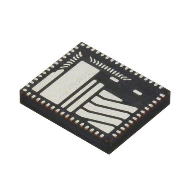
Murata Power Solutions Inc. 的 MEJ2D0503SC 是一款直流-直流转换器,属于其MEJ系列。该型号输入电压为5V DC,输出为±3V DC(双路输出),采用表面贴装封装,具有高效率、小尺寸和高可靠性等特点。

MEJ2D0503SC 主要应用于对空间和能效要求较高的电子系统中,常见使用场景包括:

1. 通信设备:用于路由器、交换机和光模块中的电源管理,提供稳定双极性电压,支持信号处理电路正常运行。
2. 工业控制与自动化:在PLC(可编程逻辑控制器)、传感器接口和数据采集系统中,为运放、ADC/DAC等模拟器件供电。
3. 医疗电子设备:适用于便携式或嵌入式医疗仪器,如监护仪、血糖仪等,因其低噪声和高稳定性,有助于保障信号精度。
4. 测试与测量仪器:为精密仪表中的模拟前端提供干净的电源,减少干扰,提升测量准确性。
5. 嵌入式系统与FPGA供电:在需要双电源供电的数字电路中,为FPGA、DSP 或微控制器的I/O接口提供±3V偏置电压。

该转换器工作温度范围宽(通常-40°C 至 +85°C),符合工业级应用需求,并具备过温、过流保护功能,适合在严苛环境中稳定运行。此外,其符合国际安全标准和环保要求(如UL/EN/IEC 62368),广泛适用于注重安全与可靠性的终端产品。
| 参数 | 数值 |
| 产品目录 | |
| 描述 | DC/DC CONV 5.2KV ISO SIP7 TH 2W隔离式DC/DC转换器 2W 5-3V SIP DUAL OUTPUT |
| 产品分类 | DC DC ConvertersDC/DC转换器 |
| 品牌 | Murata Power Solutions |
| 产品手册 | |
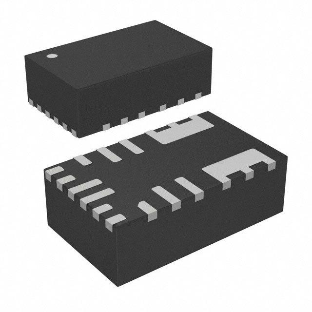
| 产品图片 |
|
| rohs | 符合RoHS无铅 / 符合限制有害物质指令(RoHS)规范要求 |
| 产品系列 | 隔离式DC/DC转换器,Murata Power Solutions MEJ2D0503SCMEJ2 |
| 数据手册 | |
| 产品型号 | MEJ2D0503SC |
| 产品 | Isolated |
| 产品种类 | 隔离式DC/DC转换器 |
| 其它名称 | 811-2384 |
| 功率(W)-制造系列 | 2W |
| 功率(W)-最大值 | 2W |
| 包装 | 管件 |
| 商标 | Murata Power Solutions |
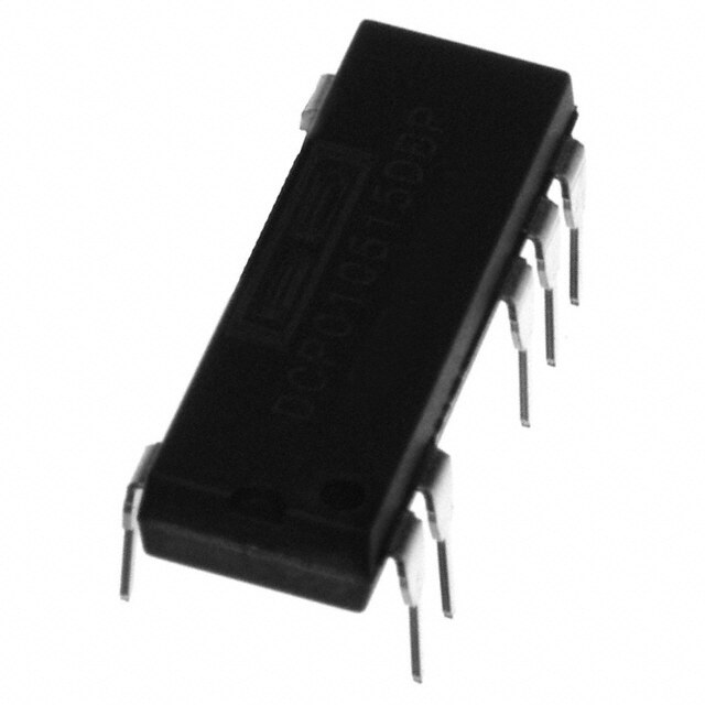
| 大小/尺寸 | 0.77" 长 x 0.39" 宽 x 0.50" 高(19.7mm x 10.0mm x 12.7mm) |
| 安装类型 | 通孔 |
| 安装风格 | Through Hole |
| 封装 | Tube |
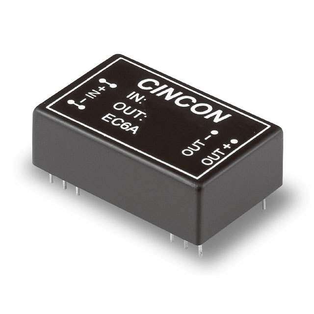
| 封装/外壳 | 7-SIP 模块(5 引线) |
| 封装/箱体尺寸 | SIP-7 |
| 工作温度 | -40°C ~ 85°C |
| 工厂包装数量 | 25 |
| 效率 | 71% |
| 标准包装 | 25 |
| 特性 | - |
| 特色产品 | http://www.digikey.cn/product-highlights/cn/zh/murata-power-solutions-mej2-dcdc-converters/3440 |
| 电压-输入(最大值) | 5.5V |
| 电压-输入(最小值) | 4.5V |
| 电压-输出1 | 3.3V |
| 电压-输出2 | -3.3V |
| 电压-输出3 | - |
| 电压-隔离 | 5.2kV(5200V) |
| 电流-输出(最大值) | 303mA,303mA |
| 类型 | 隔离模块 |
| 系列 | MEJ2 |
| 绝缘电压 | 5.2 kV |
| 输入电压—公称值 | 5 V |
| 输入电压范围 | 4.5 V to 5.5 V |
| 输出功率 | 2 W |
| 输出数 | 2 |
| 输出电压—通道1 | 3.3 V |
| 输出电压—通道2 | - 3.3 V |
| 输出电流—通道1 | 303 mA |
| 输出电流—通道2 | - 303 mA |
| 输出端数量 | 2 |


PDF Datasheet 数据手册内容提取
MEJ2 Series www.murata-ps.com 5.2kVDC Isolated 2W DC-DC Converters SELECTION GUIDE Order Code Nominal Input Voltage Output Voltage Output Current Input Current at Rated Load Load Regulation (Typ) Load Regulation (Max) Ripple & Noise (Typ)3 Ripple & Noise (Max)3 Efficiency (Min) Efficiency (Typ) MTTF2 V V mA % mVp-p % kHrs MEJ2S0303SC 3.3 3.3 606 756 14.0 17 38 55 67 70 3910 FEATURES MEJ2S0305SC 3.3 5 400 784 13.0 15 50 65 70 74 3757 (cid:132)(cid:3)RoHS compliant MEJ2S0503SC 5 3.3 606 528 10.0 15 40 55 67 70 3830 MEJ2S0505SC 5 5 400 503 8.5 10 43 55 72 75 3654 (cid:132)(cid:3)Basic/supplementary isolation to UL609502 MEJ2S0509SC 5 9 222 505 8.0 11 36 50 75 78 3472 (cid:132)(cid:3)ANSI/AAMI ES60601-1 MEJ2S0512SC 5 12 167 495 8.0 12 40 55 74 77 3663 MEJ2S0515SC 5 15 133 488 7.0 10 34 45 76 79 2629 (cid:132)(cid:3)Power density 0.81W/cm3 MEJ2S1203SC 12 3.3 606 207 9.5 11 43 60 70 73 3259 (cid:132)(cid:3)Single and dual outputs MEJ2S1205SC 12 5 400 214 8.0 10 43 60 75 78 3200 (cid:132)(cid:3)UL 94V-0 package material MEJ2S1209SC 12 9 222 205 7.0 10 35 50 75 79 2453 MEJ2S1212SC 12 12 167 207 6.5 8 35 50 76 80 2779 (cid:132)(cid:3)Footprint 1.96cm2 MEJ2S1215SC 12 15 133 205 7.0 10 32 45 76 80 2707 (cid:132)(cid:3)SIP package style MEJ2S1505SC 15 5 400 171 8.5 10 44 60 73 76 2638 MEJ2S1509SC 15 9 222 165 6.5 8 35 50 74 78 2203 (cid:132)(cid:3)5.2kVDC isolation ‘Hi Pot Test’ MEJ2S1512SC 15 12 167 164 6.5 8 38 55 74 79 2330 (cid:132)(cid:3)3.3V, 5V, 12V & 15V inputs MEJ2S1515SC 15 15 133 166 7.0 8 36 50 74 78 2100 MEJ2D0503SC 5 ±3.3 ±303 535 8.5 10 26 40 67 71 3969 (cid:132)(cid:3)3.3V, 5V, 9V, 12V & 15V output MEJ2D0505SC 5 ±5 ±200 508 7.5 9 34 50 72 76 3654 (cid:132)(cid:3)Internal SMD construction MEJ2D0509SC 5 ±9 ±111 510 6.5 8 27 40 76 79 3472 MEJ2D0512SC 5 ±12 ±83 504 5.0 8 27 40 77 80 3663 (cid:132)(cid:3)Fully encapsulated with toroidal magnetics MEJ2D0515SC 5 ±15 ±67 492 7.0 9 20 35 74 78 2629 (cid:132)(cid:3)Pin compatible with the MEV, NMV, NMK, & MEJ2D1203SC 12 ±3.3 ±303 205 8.0 9 37 55 72 75 3270 NMJ series MEJ2D1205SC 12 ±5 ±200 212 7.0 8 32 45 75 79 3268 (cid:132)(cid:3)MTTF up to 3.9 million hours MEJ2D1209SC 12 ±9 ±111 206 5.5 7 27 40 77 81 2453 MEJ2D1212SC 12 ±12 ±83 208 5.5 7 27 40 77 81 2779 (cid:132)Characterised CMTI >200kV/μS MEJ2D1215SC 12 ±15 ±67 203 6.0 7 24 40 78 82 2707 (cid:132)Continuous barrier withstand voltage MEJ2D1505SC 15 ±5 ±200 170 7.0 9 37 50 74 78 2638 2.4kVDC MEJ2D1509SC 15 ±9 ±111 163 5.5 7 26 40 76 80 2203 MEJ2D1512SC 15 ±12 ±83 167 5.5 7 26 40 75 80 2330 PRODUCT OVERVIEW MEJ2D1515SC 15 ±15 ±67 167 5.5 7 23 35 75 79 2100 The MEJ2 series are single and dual output INPUT CHARACTERISTICS medically approved DC-DC converters in a 7 pin Parameter Conditions Min. Typ. Max. Units SIP package style offering a power upgrade path Continuous operation, 3V input types 2.97 3.3 3.63 from the NMJ series SIP DC-DC converters. The Continuous operation, 5V input types 4.5 5 5.5 MEJ2 series is UL60950 and ANSI/AAMI ES60601-1 Voltage range V Continuous operation, 12V input types 10.8 12 13.2 recognised, which makes it ideal for applications Continuous operation, 15V input types 13.5 15 16.5 where safety and miniaturisation are of paramount 3.3V input types 100 140 importance. Input reflected ripple 5V input types 60 90 mA 12V & 15V input types 22 40 1. Calculated using MIL-HDBK-217 FN2 calculation model with nominal input voltage at full load. 2. See safety approvals section for limitations of use. For full details go to 3. See ripple & noise test method. www.murata-ps.com/rohs All specifications typical at TA=25°C, nominal input voltage and rated output current unless otherwise specified. www.murata-ps.com/support KDC_MEJ2_H02 Page 1 of 9
MEJ2 Series 5.2kVDC Isolated 2W DC-DC Converters ISOLATION CHARACTERISTICS Parameter Conditions Min. Typ. Max. Units Isolation test voltage Flash tested for 1 second 5200 VDC Resistance Viso= 500VDC 1 GΩ Isolation capacitance 4 pF Continuous barrier withstand voltage Non-safety barrier application 2400 V UL60950-1 Basic/supplementary 200 Safety standard ANSI/AAMI 1 MOOP 200 Vrms ES60601-1 OUTPUT CHARACTERISTICS Parameter Conditions Min. Typ. Max. Units Rated Power2 TA=-40ºC to 85ºC 2 W Voltage Set Point Accuracy See tolerance envelopes Line regulation High VIN to low VIN 1.0 1.2 %/% TEMPERATURE CHARACTERISTICS Parameter Conditions Min. Typ. Max. Units Specification All output types (see safety approval section for limitations) -40 85 Storage -55 125 MEJ2S0509SC, MEJ2S0512SC, MEJ2S0515SC, MEJ2S1209SC, MEJ2x1212SC, 27 MEJ2S1215SC, MEJ2S1509SC, MEJ2S1512SC, MEJ2S1515SC MEJ2S0503SC, MEJ2S0505SC, MEJ2S1203SC, MEJ2S1205SC, MEJ2x1505SC, °C 30 Case Temperature above ambient MEJ2S1515SC, MEJ2D0512SC, MEJ2D0515SC, MEJ2D1209SC, MEJ2D1215SC MEJ2S0305SC, MEJ2S0303SC, MEJ2S1203SC, MEJ2D0505SC, MEJ2D0509SC, 33 MEJ2D1205SC, MEJ2D1509SC, MEJ2D1512SC MEJ2D01203SC, MEJ2D0503SC 37 Cooling Free air convection GENERAL CHARACTERISTICS Parameter Conditions Min. Typ. Max. Units Switching frequency All types 45 kHz ABSOLUTE MAXIMUM RATINGS Short-circuit protection 10 minutes Lead temperature 1mm from case for 10 seconds 260°C Wave Solder profile not to exceed the profile recommended in IEC 61760-1 Wave Solder Section 6.1.3. Please refer to application notes for further information. Input voltage VIN, MEJ2x03xxSC 5V Input voltage VIN, MEJ2x05xxSC 7V Input voltage VIN, MEJ2x12xxSC 15V Input voltage VIN, MEJ2x15xxSC 18V www.murata-ps.com/support KDC_MEJ2_H02 Page 2 of 9
MEJ2 Series 5.2kVDC Isolated 2W DC-DC Converters TECHNICAL NOTES ISOLATION VOLTAGE ‘Hi Pot Test’, ‘Flash Tested’, ‘Withstand Voltage’, ‘Proof Voltage’, ‘Dielectric Withstand Voltage’ & ‘Isolation Test Voltage’ are all terms that relate to the same thing, a test voltage, applied for a specified time, across a component designed to provide electrical isolation, to verify the integrity of that isolation. Murata Power Solutions MEJ2 series of DC-DC converters are all 100% production tested at their stated isolation voltage. This is 5.2kVDC for 1 second. The MEJ2 series is recognised by Underwriters Laboratory, please see safety approval section for more information. When the insulation in the MEJ2 series is not used as a safety barrier, i.e. provides functional isolation only, continuous or switched voltages across the barrier up to 2.4kV are sustainable. This is established by measuring the partial discharge Inception voltage in accordance with IEC 60270. Please contact Murata for further information. REPEATED HIGH-VOLTAGE ISOLATION TESTING It is well known that repeated high-voltage isolation testing of a barrier component can actually degrade isolation capability, to a lesser or greater degree depending on materials, construction and environment. We therefore strongly advise against repeated high voltage isolation testing, but if it is absolutely required, that the voltage be reduced by 20% from specified test voltage. SAFETY APPROVAL ANSI/AAMI ES60601-1 The MEJ2 series have recognised by Underwriters Laboratory (UL) to ANSI/AAMI ES60601-1 and provides 1 MOOP (Means Of Operator Protection) based upon a working voltage of 200 Vrms max and 280 Vpk max., between Primary and Secondary and between Primary and its Enclosure, in a maximum ambient temperature of 85°C and/or case temperature limit of 130°C (case temperature measured on the face opposite the pins). File Number E202895 applies. UL60950 The MEJ2 series have been recognised by Underwriters Laboratory (UL) to UL60950 for basic/supplementary insulation to a working voltage of 200Vrms in a maximum ambient temperature of 85°C and/or case temperature limit of 130°C (case temperature measured on the face opposite the pins). File number E151252 applies. Creepage and clearance 2mm Working altitude 4000m FUSING The MEJ2 Series of converters are not internally fused so to meet the requirements of UL an anti-surge input line fuse should always be used with ratings as defined below. MEJ2x03xxxC: 2A MEJ2x05xxxC: 2A MEJ2x12xxxC: 750mA MEJ2x15xxxC: 750mA All fuses should be UL recognised and rated to at least the maximum allowable DC input voltage. RoHS COMPLIANCE INFORMATION This series is compatible with RoHS soldering systems with a peak wave solder temperature of 260ºC for 10 seconds. Please refer to application notes for further information. The pin termination finish on this product series is Tin Plate, Hot Dipped over Matte Tin with Nickel Preplate. The series is backward compatible with Sn/Pb soldering systems. For further information, please visit www.murata-ps.com/rohs www.murata-ps.com/support KDC_MEJ2_H02 Page 3 of 9
MEJ2 Series 5.2kVDC Isolated 2W DC-DC Converters ENVIRONMENTAL VALIDATION TESTING The following tests have been conducted on this product series, please contact Murata if further information about the tests is required. Test Standard Condition 10 cycles between two chambers set to achieve -55°C and +125°C.The dwell time shall not be Temperature cycling MIl-STD 883 1010, Condition B less than 10min. Humidity bias JEDEC STD 22-A101 85°C ± 2°C, 85% ± 5% R.H. for >1000 hours. Storage life JEDEC JESD22-A103, Condition A 125°C +10/-0°C for ≥1000 hours. 1.5mm pk-pk / 20g pk min, 20-2000Hz, 4 sweeps in each of 3 mutually perpendicular axes at Vibration MIL STD 883 Method 2007, Condition A 3 oct/min. Shock MIL STD 883 method 2002, Condition A 500g 1.0ms half sine, 5 shocks in each direction of 3 mutually perpendicular axes. ESD JESD22-A114 HBM Testing Standard at 3 stress levels; 2.0kV, 4.0kV and 8.0kV. Bump IEC Class 4M5 ofETS 300 019-2-4 Shock Spectrum Type II, 6mS duration, 250m/s2 500 bumps in 6 directions. For lead free solderability the parts are conditioned in a steam ager for 8 hours ± 15 min. at a temperature of 93±3°C. Dipped in solder at 255°C ±5°C for 5 +0/-0.5 seconds. Solderability IPC/ECA J-STD-002, Test A1 For leaded solderability the parts are conditioned in a steam ager for 8 hours ±15 min. at a temperature of 93±3°C. Dipped in solder at 245°C ±5°C for 5 +0/-0.5 seconds The test sample is subjected to a molten solder bath at 260 ±5°C for 10 seconds (96SC tin/ Solder heat JEDEC JESD22-B106 silver/copper). The soldering iron is heated to 350°C ± 10°C and applied to the terminations for a duration of 4 Solder heat (hand) MIL-STD 202 Method 210, Condition A to 5 seconds. Solvent cleaning Resistance to cleaning agents. Solvent – Novec 71IPA & Topklean EL-20A. Pulsed ultrasonic immersion 45°C- 65°C Solvent Resistance MIL-STD 883 Method 2015 Separate samples subjected to solvent A, solvent B and solvent D Lead Integrity (Adhesion) MIL-STD 883 Method 2025 Leads are bent through 90º until a fracture occurs. Lead Integrity (Fatigue) MIL-STD 883 Method 2004, condition B The leads are bent to an angle of 15º. Each lead is subjected to 3 cycles. 2 Lead Integrity (Tension/Pull) MIL-STD 883 Method 2004, Condition A Pull of 0.227kg applied for 30 seconds. The force is then increased until the pins snap. 1 PART NUMBER STRUCTURE MEJ 2 X XX XX S C Series name RoHS compliant Power rating Package type S - SIP Output type D - DIP S - Single M - Surface mount D - Dual Z - ZIP T - Triple Q - Quad Output voltage Input voltage www.murata-ps.com/support KDC_MEJ2_H02 Page 4 of 9
MEJ2 Series 5.2kVDC Isolated 2W DC-DC Converters APPLICATION NOTES Minimum load The minimum load to meet datasheet specification is 10% of the full rated load across the specified input voltage range. Lower than 10% minimum loading will result in an increase in output voltage, which may rise to typically double the specified output voltage if the output load falls to less than 5%. Gate Drive Applications Advisory Note For general guidence for product usage in gate drive applications please refer to “gate drive application notes”. Capacitive loading and start up Typical start up times for this series, with a typical input voltage rise time of 2.2μs and output capacitance of 10μF, are shown in the table below. The product series will start into a capacitance of 47μF with an increased start time, however, the maximum recommended output capacitance is 10μF. Typical Start-Up Wave Form Start-up time Start-up time Start-up time μs μs μs MEJ2S0303SC 0.89 MEJ2S1509SC 3.37 MEJ2D1505SC 1.79 MEJ2S0305SC 1.89 MEJ2S1512SC 4.47 MEJ2D1509SC 5.16 MEJ2S0503SC 1.08 MEJ2S1515SC 6.05 MEJ2D1512SC 7.04 MEJ2S0505SC 2.04 MEJ2D0503SC 1.57 MEJ2D1515SC 10.48 MEJ2S0509SC 6.5 MEJ2D0505SC 1.79 MEJ2S0512SC 8.29 MEJ2D0509SC 9.32 MEJ2S0515SC 11.4 MEJ2D0512SC 14.9 MEJ2S1203SC 0.73 MEJ2D0515SC 20.84 MEJ2S1205SC 1.61 MEJ2D1203SC 1.03 MEJ2S1209SC 4.04 MEJ2D1205SC 2.51 MEJ2S1212SC 5.51 MEJ2D1209SC 6.46 MEJ2S1215SC 7.61 MEJ2D1212SC 9.94 MEJ2S1505SC 1.33 MEJ2D1215SC 14.54 Ripple & Noise Characterisation Method Ripple and noise measurements are performed with the following test configuration. C1 1μF X7R m ultilayer ceramic capacitor, voltage rating to be a minimum of 3 times the output voltage of the DC-DC converter 10μF tantalum capacitor, voltage rating to be a minimum of 1.5 times the output voltage of the DC-DC converter with an ESR of less C2 than 100mΩ at 100 kHz C3 100nF multilayer ceramic capacitor, general purpose R1 450Ω resistor, carbon film, ±1% tolerance R2 50Ω BNC termination T1 3T of the coax cable through a ferrite toroid RLOAD Resistive load to the maximum power rating of the DC-DC converter. Connections should be made via twisted wires Measured values are multiplied by 10 to obtain the specified values. Differential Mode Noise Test Schematic DC/DC Converter OSCILLOSCOPE C1 C2 C3 R1 T1 R2 + + Y INPUT SUPPLY Input Output - - R LOAD www.murata-ps.com/support KDC_MEJ2_H02 Page 5 of 9
MEJ2 Series 5.2kVDC Isolated 2W DC-DC Converters TEMPERATURE DERATING GRAPH W)2.0 er ( w o Safe P ut 1.0 Operating Area p ut O 0.2 -40 0 40 85 Ambient Temperature (ºC) UL60950 recognition to a maximum ambient temperature of 85ºC and/or case temperature limit of 155ºC, measured on the face opposite the pins. TOLERANCE ENVELOPES The voltage tolerance envelope shows typical load regulation characteristics for this product series. The tolerance envelope is the maximum output voltage variation due to changes in output loading. MEJ2X0303SC MEJ2D0515SC 6% e 9% e g g a a Volt 2% Volt 1% 0% ut ut utp -7% utp O O -7% -7% 10 25 50 75 100 10 25 50 75 100 Output Load Current (%) Output Load Current (%) All Other Variants 10% e ag 2.5% Volt 0% ut p ut O -7.5% 10 25 50 75 100 Output Load Current (%) www.murata-ps.com/support KDC_MEJ2_H02 Page 6 of 9
MEJ2 Series 5.2kVDC Isolated 2W DC-DC Converters EFFICIENCY VS LOAD MEJ2S03XXSC MEJ2S05XXSC 90 90 80 80 70 70 %) 60 %) 60 15V Efficiency ( 345000 53V.3V Efficiency ( 345000 19532VV.V3V 20 20 10 10 0 0 0 10 20 30 40 50 60 70 80 90 100 0 10 20 30 40 50 60 70 80 90 100 Load (%) Load (%) MEJ2S12XXSC MEJ2S15XXSC 90 90 80 80 70 70 Efficiency (%) 34560000 1195352VV.VV3V Efficiency (%) 34560000 119552VVVV 20 20 10 10 0 0 0 10 20 30 40 50 60 70 80 90 100 0 10 20 30 40 50 60 70 80 90 100 Load (%) Load (%) www.murata-ps.com/support KDC_MEJ2_H02 Page 7 of 9
MEJ2 Series 5.2kVDC Isolated 2W DC-DC Converters EFFICIENCY VS LOAD MEJ2D05XXSC MEJ2D12XXSC 90 90 80 80 70 70 15V ency (%) 5600 11952VVV ency (%) 5600 1952VVV fici 40 5V fici 40 3.3V Ef 30 3.3V Ef 30 20 20 10 10 0 0 0 10 20 30 40 50 60 70 80 90 100 0 10 20 30 40 50 60 70 80 90 100 Load (%) Load (%) MEJ2D15XXSC 90 80 70 %) 60 ncy ( 50 1152VV cie 40 9V Effi 30 5V 20 10 0 0 10 20 30 40 50 60 70 80 90 100 Load (%) www.murata-ps.com/support KDC_MEJ2_H02 Page 8 of 9
MEJ2 Series 5.2kVDC Isolated 2W DC-DC Converters PACKAGE SPECIFICATIONS MECHANICAL DIMENSIONS PIN CONNECTIONS Single Output Pin Function 1 +Vin 2 -Vin 5 -Vout 7 +Vout Dual Output Pin Function 1 +VIN 2 -VIN 5 -VOUT 6* OV 7 +VOUT * All dimensions in mm (inches). Controlling dimension is mm. All pins on a 2.54 (0.100) pitch and within ±0.1 (0.004) of true postion from pin 1 at seating plane ‘S’ * Pin not fitted on single output variants. Weight: 4.3g TUBE OUTLINE DIMENSIONS RECOMMENDED FOOTPRINT DETAILS 6.00 14.20 (0.559) (0.236) 5.00 (0.197) * 5.20 (0.205) 1.50 (0.059) 0.6±0.15 (0.024±0.006) Unless otherwise stated all dimensions in mm ±0.5mm (inches ±0.02). * Hole not required for single output variants. Tube length : 20.669±0.079 (525mm±2mm). Tube Quantity : 25 All dimensions in mm ±0.25mm (inches ±0.01). This product is subject to the following operating requirements and the Life and Safety Critical Application Sales Policy: Refer to: http://www.murata-ps.com/requirements/ Murata Power Solutions (Milton Keynes) Ltd. makes no representation that the use of its products in the circuits described herein, or the use of other technical information contained herein, will not infringe upon existing or future patent rights. The descriptions contained herein do not imply the granting of licenses to make, use, or sell equipment constructed in accordance therewith. Specifications are subject to change without notice. © 2020 Murata Power Solutions (Milton Keynes) Ltd. www.murata-ps.com/support KDC_MEJ2_H02 Page 9 of 9