ICGOO在线商城 > MEA1D1215SC

 Datasheet下载
- 型号: MEA1D1215SC
- 制造商: Murata
- 库位|库存: xxxx|xxxx
- 要求:
| 数量阶梯 | 香港交货 | 国内含税 |
| +xxxx | $xxxx | ¥xxxx |
查看当月历史价格
查看今年历史价格
MEA1D1215SC产品简介:
ICGOO电子元器件商城为您提供MEA1D1215SC由Murata设计生产,在icgoo商城现货销售,并且可以通过原厂、代理商等渠道进行代购。 提供MEA1D1215SC价格参考以及MurataMEA1D1215SC封装/规格参数等产品信息。 你可以下载MEA1D1215SC参考资料、Datasheet数据手册功能说明书, 资料中有MEA1D1215SC详细功能的应用电路图电压和使用方法及教程。
| 参数 | 数值 |
| 产品目录 | |
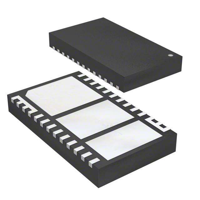
| 描述 | DC/DC CONVERTER +/-15V 1W隔离式DC/DC转换器 12Vin +/-15Vout +/-33mA 1W |
| 产品分类 | DC DC ConvertersDC/DC转换器 |
| 品牌 | Murata Power Solutions |
| 产品手册 | |
| 产品图片 | |
| rohs | RoHS 合规性豁免无铅 / 符合限制有害物质指令(RoHS)规范要求 |
| 产品系列 | 隔离式DC/DC转换器,Murata Power Solutions MEA1D1215SCMEA1 |
| mouser_ship_limit | 该产品可能需要其他文档才能发货到中国。 |
| 数据手册 | |
| 产品型号 | MEA1D1215SC |
| 产品 | Isolated |
| 产品种类 | 隔离式DC/DC转换器 |
| 功率(W)-制造系列 | 1W |
| 功率(W)-最大值 | 1W |
| 包装 | 管件 |
| 商标 | Murata Power Solutions |
| 大小/尺寸 | 0.77" 长 x 0.24" 宽 x 0.40" 高(19.7mm x 6.2mm x 10.2mm) |
| 安装类型 | 通孔 |
| 封装 | Tube |
| 封装/外壳 | 7-SIP 模块(5 引线) |
| 封装/箱体尺寸 | SIP |
| 工作温度 | -40°C ~ 85°C |
| 工厂包装数量 | 25 |
| 效率 | 88% |
| 标准包装 | 25 |
| 特性 | - |
| 电压-输入(最大值) | 13.2V |
| 电压-输入(最小值) | 10.8V |
| 电压-输出1 | 15V |
| 电压-输出2 | -15V |
| 电压-输出3 | - |
| 电压-隔离 | 1kV(1000V) |
| 电流-输出(最大值) | 33mA,33mA |
| 类型 | 隔离模块 |
| 系列 | MEA |
| 绝缘电压 | 1 kV |
| 输入电压—公称值 | 12 V |
| 输入电压范围 | 10.8 V to 13.2 V |
| 输出功率 | 0.5 W |
| 输出数 | 2 |
| 输出电压—通道1 | 15 V |
| 输出电压—通道2 | - 15 V |
| 输出电流—通道1 | 0.033 A |
| 输出电流—通道2 | - 33 mA |
| 输出端数量 | 2 |
| 输出类型 | Isolated Dual |


- 商务部:美国ITC正式对集成电路等产品启动337调查
- 曝三星4nm工艺存在良率问题 高通将骁龙8 Gen1或转产台积电
- 太阳诱电将投资9.5亿元在常州建新厂生产MLCC 预计2023年完工
- 英特尔发布欧洲新工厂建设计划 深化IDM 2.0 战略
- 台积电先进制程称霸业界 有大客户加持明年业绩稳了
- 达到5530亿美元!SIA预计今年全球半导体销售额将创下新高
- 英特尔拟将自动驾驶子公司Mobileye上市 估值或超500亿美元
- 三星加码芯片和SET,合并消费电子和移动部门,撤换高东真等 CEO
- 三星电子宣布重大人事变动 还合并消费电子和移动部门
- 海关总署:前11个月进口集成电路产品价值2.52万亿元 增长14.8%


PDF Datasheet 数据手册内容提取
MEA1 Series www.murata-ps.com 1kVDC Isolated 1W Dual Output DC-DC Converters SELECTION GUIDE Order Code Nominal Input Voltage Output Voltage Output Current Input Current at Rated Load Load Regulation (Typ) Load Regulation (Max) Ripple & Noise (Typ)1 Ripple & Noise (Max)1 Efficiency (Min.) Efficiency (Typ.) Isolation Capacitance MTTF2 MIL. Tel. V V mA mA % mVp-p % % pF kHrs MEA1D0505SC 5 ±5 ±100 233 4.8 5.4 12 25 82 85 53 3663 79541 MEA1D0509SC 5 ±9 ±56 228 3.7 4.5 8 20 84 86.5 51 3291 80891 FEATURES MEA1D0512SC 5 ±12 ±42 228 4 5 6 20 84 87 45 2860 80521 (cid:132)(cid:3)UL 60950 recognised MEA1D0515SC 5 ±15 ±33 225 3.8 4.5 6 20 84 87 46 2374 77687 MEA1D1205SC 12 ±5 ±100 98 3.5 4 9 20 81 85 44 3352 75377 (cid:132)(cid:3)Typical efficiency to 89.5% MEA1D1209SC 12 ±9 ±56 95 2.5 3 7 20 83 86.5 61 3083 79125 (cid:132)(cid:3)1kVDC isolation ‘Hi Pot Test’ MEA1D1212SC 12 ±12 ±42 93 2.6 3.5 6 20 85 89 88 2701 78770 (cid:132)(cid:3)Wide temperature performance at full MEA1D1215SC 12 ±15 ±33 94 2.2 3 5 20 84 88 78 2267 76058 MEA1D1505SC 15 ±5 ±100 78 3 3.5 8 20 80 84 40 4063 113571 1 Watt load, –40°C to 85°C MEA1D1509SC 15 ±9 ±56 76 2.1 2.5 7 20 82 87 65 4691 125575 (cid:132)(cid:3)Industry standard pinout MEA1D1512SC 15 ±12 ±42 76 2 2.5 5 20 83 87.5 75 4028 126626 (cid:132)(cid:3)Power sharing on output MEA1D1515SC 15 ±15 ±33 75 2 2.5 5 20 85 89.5 104 4103 74686 MEA1D2405SC 24 ±5 ±100 49 2.8 3.5 9 20 81 84.5 47 4581 110817 (cid:132)(cid:3)5V, 12V, 15V, 24V & 48V input MEA1D2409SC 24 ±9 ±56 47 1.8 2.5 7 20 84 87.5 80 3942 102064 (cid:132)(cid:3)5V, 9V, 12V & 15V output MEA1D2412SC 24 ±12 ±42 47 1.6 2.5 4 20 84 87 85 3247 97979 MEA1D2415SC 24 ±15 ±33 47 1.5 2.5 3 20 85 88.5 106 3658 108331 (cid:132)(cid:3)No external components required MEA1D4805SC 48 ±5 ±100 26 2.6 4 14 25 77 80 44 4332 121907 (cid:132)(cid:3)No electrolytic or tantalum capacitors MEA1D4809SC 48 ±9 ±56 25 1.6 3 8 20 79 82 72 6067 147429 MEA1D4812SC 48 ±12 ±42 25 1.6 3 7 20 78 83 91 3675 139747 (cid:132)(cid:3)Pin compatible with NKA & NMA series MEA1D4815SC 48 ±15 ±33 25 1.3 2.5 6 20 80 83.5 109 3492 73859 MEA1D0505DC 5 ±5 ±100 232 5 6.2 12 25 82 85 52 2978 88417 MEA1D0509DC 5 ±9 ±56 227 3.9 5 9 20 84 86.7 49 4087 130861 PRODUCT OVERVIEW MEA1D0512DC 5 ±12 ±42 226 4.2 5.3 7 20 84 87 47 3394 121694 The MEA series is the new high performance MEA1D0515DC 5 ±15 ±33 224 4.1 5.3 6 20 84 87.5 46 2641 105112 version of our 1W NMA series. The MEA series MEA1D1205DC 12 ±5 ±100 97 3.6 4.5 9 20 81 84.5 43 3465 112889 is more efficient and offers improved regulation MEA1D1209DC 12 ±9 ±56 95 2.6 3.5 7 20 83 86.5 64 3623 69665 performance ≤5% for applications where a wide MEA1D1212DC 12 ±12 ±42 93 2.7 3.5 6 20 85 89 89 3267 69830 output voltage variation cannot be tolerated. They MEA1D1215DC 12 ±15 ±33 94 2.3 3 6 20 84 88 76 2339 95016 are ideally suited for providing dual rail supplies MEA1D1505DC 15 ±5 ±100 78 3.1 4 9 20 80 84 42 2929 59216 with the added benefit of galvanic isolation to MEA1D1509DC 15 ±9 ±56 76 2.2 3 6 20 82 87 50 2551 96783 reduce switching noise. All of the rated power may be drawn from a single output providing the MEA1D1512DC 15 ±12 ±42 76 2 2.7 6 20 83 87.5 77 2665 102007 total load does not exceed 1 Watt. MEA1D1515DC 15 ±15 ±33 75 2 2.7 6 20 85 89.5 106 2192 87932 MEA1D2405DC 24 ±5 ±100 49 2.8 4 10 20 81 84.5 47 3427 95206 MEA1D2409DC 24 ±9 ±56 48 2 3.8 8 20 84 87 77 3686 110546 MEA1D2412DC 24 ±12 ±42 47 1.6 2.5 6 20 84 87 83 2855 62894 MEA1D2415DC 24 ±15 ±33 47 1.5 2.3 6 20 85 88 100 2435 90783 1. See Ripple & Noise characterisation method. 2. Calculated using MIL-HDBK-217 FN2 and Telcordia SR-332 calculation model with nominal input voltage at full load. For full details go to www.murata-ps.com/rohs All specifications typical at TA=25°C, nominal input voltage and rated output current unless otherwise specified. www.murata-ps.com/support KDC_MEA1.C10 Page 1 of 9
MEA1 Series 1kVDC Isolated 1W Dual Output DC-DC Converters INPUT CHARACTERISTICS Parameter Conditions Min. Typ. Max. Units Continuous operation, 5V input types 4.5 5 5.5 Continuous operation, 12V input types 10.8 12 13.2 Voltage range Continuous operation, 15V input types 13.5 15 16.5 V Continuous operation, 24V input types 21.6 24 26.4 Continuous operation, 48V input types 43.2 48 52.8 5V input types 4 12 12V input types 4 12 Reflected ripple current 15V input types 3 10 mA p-p 24V input types 3 10 48V input types 22 35 OUTPUT CHARACTERISTICS Parameter Conditions Min. Typ. Max. Units Rated Power TA=-40°C to 85°C 1 W Voltage Set Point Accuracy See tolerance envelope Line regulation High VIN to low VIN 1.05 1.1 %/% ISOLATION CHARACTERISTICS Parameter Conditions Min. Typ. Max. Units Isolation test voltage Flash tested for 1 second 1000 VDC Resistance Viso= 1000VDC 10 GΩ GENERAL CHARACTERISTICS Parameter Conditions Min. Typ. Max. Units MEA1D05xxxC, MEA1D1212xC, MEA1D1515xC 65 MEA1D1205xC, MEA1D1209xC, MEA1D1215xC, MEA1D1505xC, Switching frequency 85 kHz MEA1D1509xC, MEA1D1512xC, MEA1D24xxxC MEA1D48xxxC 60 TEMPERATURE CHARACTERISTICS Parameter Conditions Min. Typ. Max. Units Specification All output types -40 85 Storage -50 125 °C Case Temperature above ambient 20 Cooling Free air convection ABSOLUTE MAXIMUM RATINGS Lead temperature 1mm from case for 10 seconds 260°C Input voltage VIN, 5Vin types 7V Input voltage VIN, 12Vin types 15V Input voltage VIN, 15Vin types 18V Input voltage VIN, 24Vin types 28V Input voltage VIN, 48Vin types 54V www.murata-ps.com/support KDC_MEA1.C10 Page 2 of 9
MEA1 Series 1kVDC Isolated 1W Dual Output DC-DC Converters TECHNICAL NOTES ISOLATION VOLTAGE ‘Hi Pot Test’, ‘Flash Tested’, ‘Withstand Voltage’, ‘Proof Voltage’, ‘Dielectric Withstand Voltage’ & ‘Isolation Test Voltage’ are all terms that relate to the same thing, a test voltage, applied for a specified time, across a component designed to provide electrical isolation, to verify the integrity of that isolation. Murata Power Solutions MEA1 series of DC-DC converters are all 100% production tested at their stated isolation voltage. This is 1kVDC for 1 second. A question commonly asked is, “What is the continuous voltage that can be applied across the part in normal operation?” The MEA1 has been recognised by Underwriters Laboratory for functional insulation, both input and output should normally be maintained within SELV limits i.e. less than 42.4V peak, or 60VDC. The isolation test voltage represents a measure of immunity to transient voltages and the part should never be used as an element of a safety isolation system. The part could be expected to function correctly with several hundred volts offset applied continuously across the isolation barrier; but then the circuitry on both sides of the barrier must be regarded as operating at an unsafe voltage and further isolation/insulation systems must form a barrier between these circuits and any user-accessible circuitry according to safety standard requirements. REPEATED HIGH-VOLTAGE ISOLATION TESTING It is well known that repeated high-voltage isolation testing of a barrier component can actually degrade isolation capability, to a lesser or greater degree depending on materi- als, construction and environment. The MEA1 series has toroidal isolation transformers, with no additional insulation between primary and secondary windings of enamelled wire. While parts can be expected to withstand several times the stated test voltage, the isolation capability does depend on the wire insulation. Any material, including this enamel (typically polyurethane) is susceptible to eventual chemical degradation when subject to very high applied voltages thus implying that the number of tests should be strictly limited. We therefore strongly advise against repeated high voltage isolation testing, but if it is absolutely required, that the voltage be reduced by 20% from specified test voltage. This consideration equally applies to agency recognised parts rated for better than functional isolation where the wire enamel insulation is always supplemented by a further insulation system of physical spacing or barriers. SAFETY APPROVAL The MEA1 series has been recognised by Underwriters Laboratory (UL) to UL 60950 for functional insulation in a maximum ambient temperature of 85°C and/or case temperature limit of 130°C (case temperature measured on the face opposite the pins). File number E151252 applies. The MEA1 Series of converters are not internally fused so to meet the requirements of UL 60950 an anti-surge input line fuse should always be used with ratings as defined below. MEA1D05xxxC: 1A MEA1D12xxxC: 0.375A MEA1D15xxxC: 0.375A MEA1D24xxxC: 0.2A MEA1D48xxSC: 0.1A All fuses should be UL approved and rated to at least the maximum allowable DC input voltage. RoHS COMPLIANT INFORMATION This series is compatible with RoHS soldering systems with a peak wave solder temperature of 260°C for 10 seconds. The pin termination finish on the SIP package type is Tin Plate, Hot Dipped over Matte Tin with Nickel Preplate. The DIP types are Matte Tin over Nickel Preplate. Both types in this series are backward compatible with Sn/Pb soldering systems. For further information, please visit www.murata-ps.com/rohs PART NUMBER STRUCTURE MEA 1 D XX XX S C Series name Power rating Output type RoHS compliant S - Single Package type D - Dual S - SIP Input voltage D - DIP M - Surface mount Z - ZIP Output voltage www.murata-ps.com/support KDC_MEA1.C10 Page 3 of 9
MEA1 Series 1kVDC Isolated 1W Dual Output DC-DC Converters APPLICATION NOTES Minimum load The minimum load to meet datasheet specification is 10% of the full rated load across the specified input voltage range. Lower than 10% minimum loading will result in an increase in output voltage, which may rise to typically double the specified output voltage if the output load falls to less than 5%. Capacitive loading and start up Typical start up times for this series, with a typical input voltage rise time of 2.2μs and output capacitance of 10μF, are shown in the table below. The product series will start into a capacitance of 47μF with an increased start time, however, the maximum recommended output capacitance is 10μF. Start-up time Start-up time Typical Start-Up Wave Form μs μs MEA1D0505xC 939 MEA1D1512xC 5630 MEA1D0509xC 2872 MEA1D1515xC 8585 MEA1D0512xC 5325 MEA1D2405xC 472 MEA1D0515xC 8895 MEA1D2409xC 1473 MEA1D1205xC 1150 MEA1D2412xC 2643 MEA1D1209xC 3716 MEA1D2415xC 4348 MEA1D1212xC 6912 MEA1D4805xC 586 MEA1D1215xC 10810 MEA1D4809xC 1705 MEA1D1505xC 883 MEA1D4812xC 2995 MEA1D1509xC 3160 MEA1D4815xC 4722 Ripple & Noise Characterisation Method Ripple and noise measurements are performed with the following test configuration. C1 1μF X7R m ultilayer ceramic capacitor, voltage rating to be a minimum of 3 times the output voltage of the DC-DC converter 10μF tantalum capacitor, voltage rating to be a minimum of 1.5 times the output voltage of the DC-DC converter with an ESR of less C2 than 100mΩ at 100 kHz C3 100nF multilayer ceramic capacitor, general purpose R1 450Ω resistor, carbon film, ±1% tolerance R2 50Ω BNC termination T1 3T of the coax cable through a ferrite toroid RLOAD Resistive load to the maximum power rating of the DC-DC converter. Connections should be made via twisted wires Measured values are multiplied by 10 to obtain the specified values. Differential Mode Noise Test Schematic DC/DC Converter OSCILLOSCOPE C1 C2 C3 R1 T1 R2 + + Y INPUT SUPPLY Input Output - - R LOAD www.murata-ps.com/support KDC_MEA1.C10 Page 4 of 9
MEA1 Series 1kVDC Isolated 1W Dual Output DC-DC Converters APPLICATION NOTES (continued) Output Ripple Reduction By using the values of inductance and capacitance stated, the output ripple at the rated load is lowered to 5mV p-p max. Component selection Capacitor: It is required that the ESR (Equivalent Series Resistance) should be as low as possible, ceramic types are recommended. The voltage rating should be at least twice (except for 15V output), the rated output voltage of the DC-DC converter. Inductor: The rated current of the inductor should not be less than that of the output of the DC-DC converter. At the rated current, the DC resistance of the inductor should be such that the voltage drop across the inductor is <2% of the rated voltage of the DC-DC converter. The SRF (Self Resonant Frequency) should be >20MHz. +VOUT L DC C Load Power OV Source DC C Load -VOUT L Inductor Capacitor L, μH SMD Through Hole C, μF MEA1D0505xC 10 82103C 11R103C 4.7 MEA1D0509xC 22 82223C 11R223C 2.2 MEA1D0512xC 47 82473C 11R473C 1 MEA1D0515xC 47 82473C 11R473C 1 MEA1D1205xC 10 82103C 11R103C 4.7 MEA1D1209xC 22 82223C 11R223C 2.2 MEA1D1212xC 47 82473C 11R473C 1 MEA1D1215xC 47 82473C 11R473C 1 MEA1D1505xC 10 82103C 11R103C 4.7 MEA1D1509xC 22 82223C 11R223C 2.2 MEA1D1512xC 47 82473C 11R473C 1 MEA1D1515xC 47 82473C 11R473C 1 MEA1D2405xC 10 82103C 11R103C 4.7 MEA1D2409xC 22 82223C 11R223C 2.2 MEA1D2412xC 47 82473C 11R473C 1 MEA1D2415xC 47 82473C 11R473C 1 MEA1D4805xC 10 82103C 11R103C 4.7 MEA1D4809xC 22 82223C 11R223C 2.2 MEA1D4812xC 47 82473C 11R473C 1 MEA1D4815xC 47 82473C 11R473C 1 www.murata-ps.com/support KDC_MEA1.C10 Page 5 of 9
MEA1 Series 1kVDC Isolated 1W Dual Output DC-DC Converters TEMPERATURE DERATING GRAPH 1.5 85°C W) 1.0 er ( w o P 0.5 Safe Operating Area ut p ut O 0 -40 0 50 100 150 Ambient Temperature (°C) TOLERANCE ENVELOPES The voltage tolerance envelopes show typical load regulation characteristics for this product series. The tolerance envelope is the maximum output voltage variation due to the changes in output loading. MEA1 5% Output Voltage 0% -42%% 10 25 50 75 100 Output Load Current (%) www.murata-ps.com/support KDC_MEA1.C10 Page 6 of 9
MEA1 Series 1kVDC Isolated 1W Dual Output DC-DC Converters EFFICIENCY VS LOAD 5V Input 12V Input 90 90 80 80 70 15V 70 15V Efficiency (%) 34560000 1952VVV Efficiency (%) 34560000 1952VVV 20 20 10 10 0 0 0 10 20 30 40 50 60 70 80 90 100 0 10 20 30 40 50 60 70 80 90 100 Load (%) Load (%) 15V Input 24V Input 90 90 80 80 70 15V 70 Efficiency (%) 34560000 1952VVV Efficiency (%) 34560000 119552VVVV 20 20 10 10 0 0 0 10 20 30 40 50 60 70 80 90 100 0 10 20 30 40 50 60 70 80 90 100 Load (%) Load (%) 48V Input 90 80 70 15V %) 60 12V ncy ( 50 95VV e fici 40 Ef 30 20 10 0 0 10 20 30 40 50 60 70 80 90 100 Load (%) www.murata-ps.com/support KDC_MEA1.C10 Page 7 of 9
MEA1 Series 1kVDC Isolated 1W Dual Output DC-DC Converters PACKAGE SPECIFICATIONS MECHANICAL DIMENSIONS PIN CONNECTIONS - 14 PIN DIP DIP package SIP package Pin Function 1 -VIN 7 NC 8 OV * MEA1XXXXXDC 9 +VOUT 11 -VOUT 14 +VIN MEA1XXXXXSC PIN CONNECTIONS - 7 PIN SIP XYYWW Pin Function 1 +VIN 2 -VIN 4 -VOUT 5 OV 6 +VOUT *48V input variants 7.5 (0.295) All dimensions in mm (inches). Controlling dimension is mm. Weight: 2.5g (DIP) 2.3g (SIP) All pins on a 2.54 (0.100”) pitch and within ±0.1 (0.004”) of true position from pin 1 at seating plane ‘S’. 48V input: 2.8g www.murata-ps.com/support KDC_MEA1.C10 Page 8 of 9
MEA1 Series 1kVDC Isolated 1W Dual Output DC-DC Converters PACKAGE SPECIFICATIONS (continued) RECOMMENDED FOOTPRINT DETAILS 14 Pin DIP Package 7 Pin SIP Package 1.15 (0.045) Ø51 .H00O L(0E.S039) Ø11..1050 ((00..004359)) 5 HOLES 2.54 (0.1) 2.54 (0.1) 2.54 (0.1) 2.54 (0.1) Unless otherwise stated all dimensions in mm (inches) ±0.5mm. TUBE OUTLINE DIMENSIONS 14 Pin DIP Tube 7 Pin SIP Tube 12.0 [0.472] 9.3 [0.366] 12.43 [0.489] 14.5 [0.571] 18.0 [0.709] 5.07±0.80 [0.200±0.03] 5.05 [0.199] 5.0 [0.197] Unless otherwise specified all dimensions in mm [inches] ±0.55mm [0.022].. Tube length (14 Pin DIP) : 520mm [20.472] ±2.0 [0.079]. Tube length (7 Pin SIP) : 520mm [20.472] ±2.0 [0.079]. Tube Quantity : 25 This product is subject to the following operating requirements and the Life and Safety Critical Application Sales Policy: Refer to: http://www.murata-ps.com/requirements/ Murata Power Solutions, Inc. makes no representation that the use of its products in the circuits described herein, or the use of other technical information contained herein, will not infringe upon existing or future patent rights. The descriptions contained herein do not imply the granting of licenses to make, use, or sell equipment constructed in accordance therewith. Specifications are subject to change without notice. © 2019 Murata Power Solutions, Inc. www.murata-ps.com/support KDC_MEA1.C10 Page 9 of 9
Mouser Electronics Authorized Distributor Click to View Pricing, Inventory, Delivery & Lifecycle Information: M urata: MEA1D0505SC MEA1D0509SC MEA1D0512SC MEA1D0515SC MEA1D1205SC MEA1D1209SC MEA1D1212SC MEA1D1215SC MEA1D0505DC MEA1D0509DC MEA1D0512DC MEA1D0515DC MEA1D1205DC MEA1D1209DC MEA1D1212DC MEA1D1215DC MEA1D1505DC MEA1D1509DC MEA1D1512DC MEA1D1515DC MEA1D2405DC MEA1D2409DC MEA1D2412DC MEA1D2415DC MEA1D1505SC MEA1D1509SC MEA1D1512SC MEA1D1515SC MEA1D2405SC MEA1D2409SC MEA1D2412SC MEA1D2415SC MEA1D4805SC MEA1D4809SC MEA1D4812SC MEA1D4815SC