ICGOO在线商城 > 晶体,振荡器,谐振器 > 振荡器 > MAX7375AXR185+T

 Datasheet下载
- 型号: MAX7375AXR185+T
- 制造商: Maxim
- 库位|库存: xxxx|xxxx
- 要求:
| 数量阶梯 | 香港交货 | 国内含税 |
| +xxxx | $xxxx | ¥xxxx |
查看当月历史价格
查看今年历史价格
MAX7375AXR185+T产品简介:
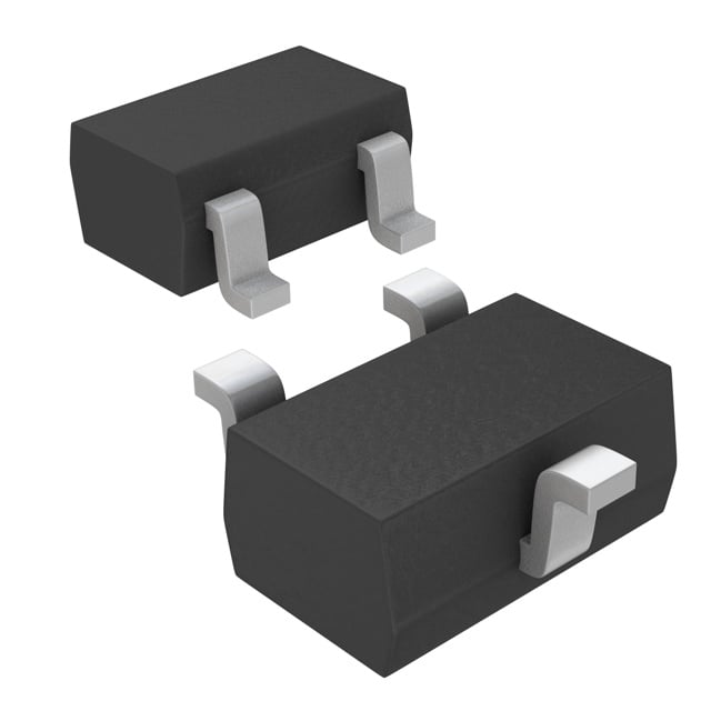
ICGOO电子元器件商城为您提供MAX7375AXR185+T由Maxim设计生产,在icgoo商城现货销售,并且可以通过原厂、代理商等渠道进行代购。 MAX7375AXR185+T价格参考。MaximMAX7375AXR185+T封装/规格:振荡器, 1.84MHz XO (Standard) CMOS Oscillator 2.7V ~ 5.5V SC-70, SOT-323。您可以下载MAX7375AXR185+T参考资料、Datasheet数据手册功能说明书,资料中有MAX7375AXR185+T 详细功能的应用电路图电压和使用方法及教程。
MAX7375AXR185+T是Maxim Integrated推出的一款集成振荡器的专用定时器件,主要应用于需要高精度时钟信号和低功耗性能的便携式电子设备中。该器件内置高频振荡器,可提供稳定的参考时钟,适用于通信模块、消费类电子产品和工业控制系统等场景。

典型应用包括智能手机、平板电脑、可穿戴设备(如智能手表和健康监测设备)中的系统时序管理,也可用于无线传感器网络和物联网(IoT)终端设备中,为微控制器、传感器接口或无线收发模块提供精确时钟源。其小尺寸封装(如晶圆级封装)和低功耗特性特别适合空间受限且依赖电池供电的应用。

此外,MAX7375AXR185+T还可用于需要电源管理和时序控制的混合信号系统中,配合其他IC实现高效的系统同步与节能运行。由于具备良好的温度稳定性和长期可靠性,该器件也适用于工业级环境下的嵌入式控制单元和远程监控设备。

综上,MAX7375AXR185+T凭借其集成度高、体积小、功耗低和时钟精度高等优点,广泛应用于对小型化和能效要求较高的现代电子系统中。
| 参数 | 数值 |
| 产品目录 | 集成电路 (IC)半导体 |
| 描述 | IC OSC SILICON 1.84MHZ SC70-3计时器和支持产品 MAX7375AXR185+T |
| 产品分类 | |
| 品牌 | Maxim Integrated |
| 产品手册 | |
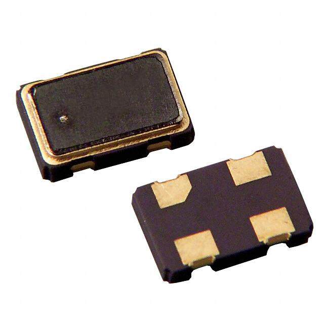
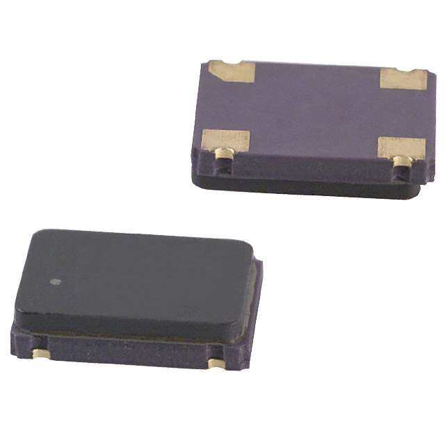
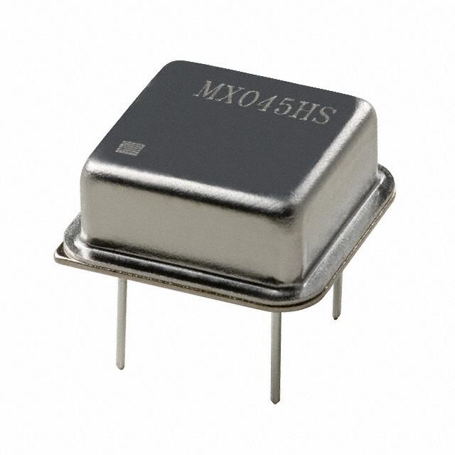
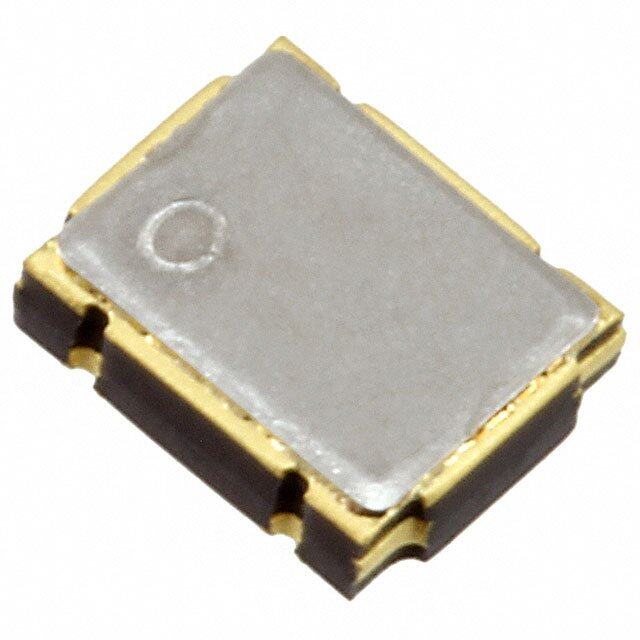
| 产品图片 |
|
| rohs | 符合RoHS无铅 / 符合限制有害物质指令(RoHS)规范要求 |
| 产品系列 | 时钟和计时器IC,计时器和支持产品,Maxim Integrated MAX7375AXR185+T- |
| 数据手册 | |
| 产品型号 | MAX7375AXR185+T |
| 产品培训模块 | http://www.digikey.cn/PTM/IndividualPTM.page?site=cn&lang=zhs&ptm=25703http://www.digikey.cn/PTM/IndividualPTM.page?site=cn&lang=zhs&ptm=25705 |
| 产品种类 | 计时器和支持产品 |
| 供应商器件封装 | SC-70-3 |
| 其它名称 | MAX7375AXR185+TCT |
| 包装 | 剪切带 (CT) |
| 商标 | Maxim Integrated |
| 安装类型 | 表面贴装 |
| 安装风格 | SMD/SMT |
| 封装 | Reel |
| 封装/外壳 | SC-70,SOT-323 |
| 封装/箱体 | SC-70-3 |
| 工作温度 | -40°C ~ 125°C |
| 工厂包装数量 | 2500 |
| 应用说明 | 点击此处下载产品Datasheet点击此处下载产品Datasheet点击此处下载产品Datasheet点击此处下载产品Datasheet点击此处下载产品Datasheet点击此处下载产品Datasheet |
| 最大功率耗散 | 235 mW |
| 最大工作温度 | + 125 C |
| 最小工作温度 | - 40 C |
| 标准包装 | 1 |
| 电压-电源 | 2.7 V ~ 5.5 V |
| 电流-电源 | 800µA |
| 电源电压-最大 | 5.5 V |
| 电源电压-最小 | 2.7 V |
| 类型 | 振荡器 - 硅 |
| 系列 | MAX7375 |
| 计数 | - |
| 零件号别名 | MAX7375 |
| 频率 | 1.84MHz |


- 商务部:美国ITC正式对集成电路等产品启动337调查
- 曝三星4nm工艺存在良率问题 高通将骁龙8 Gen1或转产台积电
- 太阳诱电将投资9.5亿元在常州建新厂生产MLCC 预计2023年完工
- 英特尔发布欧洲新工厂建设计划 深化IDM 2.0 战略
- 台积电先进制程称霸业界 有大客户加持明年业绩稳了
- 达到5530亿美元!SIA预计今年全球半导体销售额将创下新高
- 英特尔拟将自动驾驶子公司Mobileye上市 估值或超500亿美元
- 三星加码芯片和SET,合并消费电子和移动部门,撤换高东真等 CEO
- 三星电子宣布重大人事变动 还合并消费电子和移动部门
- 海关总署:前11个月进口集成电路产品价值2.52万亿元 增长14.8%


PDF Datasheet 数据手册内容提取
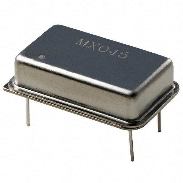
MAX7375 3-Pin Silicon Oscillator General Description Features The MAX7375 is a silicon oscillator, intended as a low-cost ● 2.7V to 5.5V Operation improvement replacing ceramic resonators, crystals, and ● Factory-Trimmed Oscillator (600kHz to 9.99MHz) crystal oscillator modules used as the clock source for micro- controllers and UARTs in 3V, 3.3V, and 5V applications. ● No External Components Required The MAX7375 is a fully integrated oscillator, supplied at ● ±10mA Output Drive Current specific factory-trimmed frequencies with a rail-to-rail 50% ● 2% Initial Accuracy duty cycle square-wave output. The oscillator frequency is ● ±50ppm/°C Temp Drift generated directly without the use of a phase-locked loop (PLL). No additional components are used to set or adjust ● Fast Startup Time: 5µs the frequency. ● 40% to 60% Maximum Duty Cycle Unlike typical crystal and ceramic resonator oscillator circuits, ● 5ns Output Rise and Fall Time-Low EMI the MAX7375 is highly resistant to vibration and EMI. The high output drive current and absence of high-impedance ● Very Low EMI Susceptibility-No High-Impedance nodes also makes the oscillator less susceptible to dirty Nodes or humid operating conditions. With a wide operating tem- ● Very Low Jitter: 160ps at 8MHz P-P perature range, the oscillator is a good choice for demanding ● Tiny Surface-Mount Package (SC70) home appliance environments. ● -40°C to +125°C Temperature Range Available in 3-pin space-saving SC70 package, the MAX7375 is offered in standard and nonstandard factory- Ordering Information set frequencies ranging from 600kHz to 9.99MHz. See the MAX7381 data sheet for frequencies ≥ 10MHz. The PART TEMP RANGE PIN-PACKAGE MAX7375’s standard operating temperature range is MAX7375AXR105-T -40°C to +125°C 3 SC70-3 -40°C to +125°C. See the Applications Information sec- MAX7375AXR185-T -40°C to +125°C 3 SC70-3 tion for extended operating temperature range. MAX7375AXR365-T -40°C to +125°C 3 SC70-3 Applications MAX7375AXR375-T -40°C to +125°C 3 SC70-3 ● White Goods ● Portable Equipment ● Appliances and Controls ● Microcontroller Systems MAX7375AXR405-T -40°C to +125°C 3 SC70-3 ● Hand-Held Products MAX7375AXR425-T -40°C to +125°C 3 SC70-3 MAX7375AXR805-T -40°C to +125°C 3 SC70-3 Typical Application Circuit Note: The MAX7375 is available in factory-set frequencies from 600kHz to 9.99MHz. There are seven standard versions (1MHz, 1.84MHz, 3.58MHz, 3.69MHz, 4MHz, 4.19MHz, and 2.7V TO 5.5V 8MHz, as shown in the Selector Guide) with a required 2.5k order increment. Nonstandard frequencies are also available V+ CLOCK OSC1 µC with a required 10k order increment. For nonstandard versions, contact factory for availability and ordering information. All ver- sions available in tape-and-reel only. MAX7375 Pin Configuration and Selector Guide appear at end of data GND sheet. OSC2 19-3060; Rev 4; 4/14
MAX7375 3-Pin Silicon Oscillator Absolute Maximum Ratings V+ to GND ...............................................................-0.3V to +6V Operating Temperature Range .........................-55°C to +135°C CLOCK to GND ...........................................-0.3V to (V+ + 0.3V) Junction Temperature ......................................................+150°C Continuous Power Dissipation (TA = +70°C) Storage Temperature Range ............................-65°C to +150°C 3-Pin SC70 (derate 2.9mW/°C over +70°C) ................235mW Lead Temperature (soldering, 10s) .................................+300°C Stresses beyond those listed under “Absolute Maximum Ratings” may cause permanent damage to the device. These are stress ratings only, and functional operation of the device at these or any other conditions beyond those indicated in the operational sections of the specifications is not implied. Exposure to absolute maximum rating conditions for extended periods may affect device reliability. Electrical Characteristics (V+ = 2.7V to 5.5V, TA = -40°C to +125°C, unless otherwise noted. Typical values are at V+ = 5V, TA = +25°C, unless otherwise noted.) (Note 1) PARAMETER SYMBOL CONDITIONS MIN TYP MAX UNITS Operating Supply Voltage V+ 2.7 5.5 V MAX7375A_R105 0.55 1.1 MAX7375A_R185 0.8 1.25 Operating Supply Current I+ mA MAX7375A_R405 1.7 4.2 MAX7375A_R805 3.2 6.4 V+ ≥ 2.7V, ISOURCE = 2.5mA V+ - 0.4 Output High Voltage VOH V V+ ≥ 4.5V, ISOURCE = 9mA V+ - 0.4 V+ ≥ 2.7, ISINK = 10mA 0.4 Output Low Voltage VOL V V+ ≥ 4.5V, ISINK = 20mA 0.4 V+ = 3.0V, MAX7375A_R_ _ _ -2 +2 Initial CLOCK Frequency TA = +25°C (Note 2) Accuracy fCLOCK V+ = 2.7V to 5.5V, % MAX7375A_R_ _ _ -4 +4 TA = +25°C (Note 2) CLOCK Frequency Temperature (Note 3) ±50 ±325 ppm/°C Sensitivity Duty Cycle (Note 3) 45 52 57 % Observation for 20s using a 500MHz Output Jitter oscilloscope (MAX7375A_R805) 160 psP-P Output Rise Time tR (Note 3) 5.0 ns Output Fall Time tF (Note 3) 2.5 ns Note 1: All parameters are tested at TA = +25°C. Specifications over temperature are guaranteed by design and characterization. Note 2: Typical frequencies are nominal values. Note 3: Guaranteed by design and characterization. Not production tested. www.maximintegrated.com Maxim Integrated │ 2
MAX7375 3-Pin Silicon Oscillator Typical Operating Characteristics (V+ = 5V, TA = +25°C, CL = 10pF, 8MHz output, unless otherwise noted.) DUTY CYCLE vs. TEMPERATURE DUTY CYCLE vs. SUPPLY VOLTAGE SUPPLY CURRENT vs. TEMPERATURE 555345 MAX7375 toc01 5535 MAX7375 toc02 34..50 V+ = 5V MAX7375 toc03 A) 3.0 DUTY CYCLE (%) 45559012 DUTY CYCLE (%) 4591 PPLY CURRENT (m 122...505 V+ = 3.3V 48 U S 1.0 47 47 V+ = 2.7V 0.5 46 45 45 0 -40 -25 -10 5 20 35 50 65 80 95 110125 2.7 3.4 4.1 4.8 5.5 -40 -25 -10 5 20 35 50 65 80 95 110125 TEMPERATURE (°C) SUPPLY VOLTAGE (V) TEMPERATURE (°C) SUPPLY CURRENT vs. SUPPLY VOLTAGE FREQUENCY vs. SUPPLY VOLTAGE FREQUENCY vs. TEMPERATURE 34..50 MAX7375 toc04 Y11..000002 MAX7375 toc05 Y11..001250 MAX7375 toc06 URRENT (mA) 23..50 D FREQUENC00..999968 D FREQUENC111...000010005 C E E PPLY 2.0 MALIZ0.994 MALIZ0.995 U R R S NO NO0.990 1.5 0.992 0.985 1.0 0.990 0.980 2.7 3.4 4.1 4.8 5.5 2.7 3.4 4.1 4.8 5.5 -40 -15 10 35 60 85 110 135 SUPPLY VOLTAGE (V) SUPPLY VOLTAGE (V) TEMPERATURE (°C) CLOCK OUTPUT WAVEFORM SUPPLY CURRENT vs. FREQUENCY SETTLING TIME FROM START WITH CL = 10pF 34..50 V+ = 5.5V MAX7375 toc07 MAX7375 toc08 MAX7375 toc09 A) 3.0 CLOCK T (m 2V/div N 2.5 E R R U 2.0 V+ = 5V CLOCK Y C V+ = 3.3V V+ 1V/div PL 1.5 2V/div P U S 1.0 0.5 V+ = 2.7V V+ = 3.3V V+ = 3.3V 0 0.5 2.5 4.5 6.5 8.5 1µs/div 40ns/div FREQUENCY (MHz) www.maximintegrated.com Maxim Integrated │ 3
MAX7375 3-Pin Silicon Oscillator Typical Operating Characteristics (continued) (V+ = 5V, TA = +25°C, CL = 10pF, 8MHz output, unless otherwise noted.) CLOCK OUTPUT WAVEFORM CLOCK OUTPUT WAVEFORM WITH CL = 50pF WITH CL = 100pF MAX7375 toc10 MAX7375 toc11 CLOCK CLOCK 1V/div 1V/div V+ = 3.3V V+ = 3.3V 40ns/div 40ns/div Pin Description PIN NAME FUNCTION SC70 1 V+ Positive Supply Voltage 2 CLOCK Clock Output. Output is push-pull. 3 GND Ground Detailed Description supply connected 500Ω load to within 300mV of either supply rail. The clock output remains stable over the full The MAX7375 is a replacement for ceramic resonators, operating voltage range and does not generate short out- crystals, and crystal oscillator modules as the clock put cycles during either power on or power off. A typical source for microcontrollers and UARTs in 3V, 3.3V, and startup characteristic is shown in the Typical Operating 5V applications. The MAX7375 is an integrated oscilla- Characteristics section. tor, supplied at specific frequencies just like crystals and resonators. A variety of popular standard frequencies are Output Jitter available. No external components are required for setting The MAX7375’s jitter performance is given in the Electrical or adjusting the frequency. Characteristics table as a peak-to-peak value obtained Supply Voltages by observing the output of the MAX7375 for 20s with a 500MHz oscilloscope. Jitter measurements are approxi- The MAX7375 has been designed for use in systems with mately proportional to the period of the output frequency nominal supply voltages of 3V, 3.3V, or 5V and is speci- of the device. Thus, a 4MHz part has approximately twice fied for operation with supply voltages in the 2.7V to 5.5V the jitter value of an 8MHz part. range. Operation outside this range is not guaranteed. See the Absolute Maximum Ratings table for limit values The jitter performance of all clock sources degrades in the of power-supply and pin voltages. presence of mechanical and electrical interference. The MAX7375 is relatively immune to vibration, shock, and Oscillator EMI influences and thus provides a considerably more The clock output is a push-pull configuration and is capa- robust clock source than crystal- or ceramic-resonator- ble of driving a ground-connected 1kΩ load or a positive based oscillator circuits. www.maximintegrated.com Maxim Integrated │ 4
MAX7375 3-Pin Silicon Oscillator Applications Information Extended Temperature Operation The MAX7375 was tested to +135°C during product Interfacing to a Microcontroller Clock Input characterization and shown to function normally at this The MAX7375 clock output is a push-pull, CMOS, logic temperature (see Typical Operating Characteristics). output, which directly drives any microprocessor (µP) or However, production test and qualification is only per- microcontroller (µC) clock input. There are no impedance- formed from -40°C to +125°C at this time. Contact the matching issues when using the MAX7375. Operate factory if operation outside this range is required. the MAX7375 and microcontroller (or other clock input device) from the same supply voltage level. Refer to the Power-Supply Considerations microcontroller data sheet for clock input compatibility The MAX7375 operates with power-supply voltages in with external clock signals. the 2.7V to 5.5V range. Good power-supply decoupling The MAX7375 requires no biasing components or load is needed to maintain the power-supply rejection per- capacitance. When using the MAX7375 to retrofit a crys- formance of the MAX7375. Use a 0.1µF surface-mount tal oscillator, remove all biasing components from the ceramic capacitor connected between V+ and GND and oscillator input. mounted as close as possible to the device. If possible, mount the MAX7375 close to the microcontroller’s decou- Startup Performance pling capacitor so that additional decoupling is not required. The MAX7375 oscillator output stabilizes within a few A larger value of bypass capacitor is recommended if the cycles of operation after V+ rises to a sufficient voltage to MAX7375 is to operate with a large capacitive load. Use start the oscillator, typically 1.65V at +25°C. Use a reset a bypass capacitor value of at least 1000 times that of the or similar voltage-detection circuit to disable devices con- output load capacitance. nected to the MAX7375 until 5µs after the voltage on V+ has risen above 2.7V. Selector Guide Pin Configuration PART FREQUENCY (MHz) TOP MARK TOP VIEW MAX7375AXR105 1.00 AOV MAX7375AXR185 1.84 AOU MAX7375AXR365 3.58 AOT V+ 1 MAX7375AXR375 3.69 AOS MAX7375AXR 3 GND MAX7375AXR405 4.00 AOR MAX7375AXR425 4.19 AOQ CLOCK 2 MAX7375AXR805 8.00 AOP SC70 Chip Information PROCESS: BiCMOS www.maximintegrated.com Maxim Integrated │ 5
MAX7375 3-Pin Silicon Oscillator Package Information For the latest package outline information and land patterns (footprints), go to www.maximintegrated.com/packages. Note that a “+”, “#”, or “-” in the package code indicates RoHS status only. Package drawings may show a different suffix character, but the drawing pertains to the package regardless of RoHS status. PACKAGE TYPE PACKAGE CODE DOCUMENT NO. LAND PATTERN NO. 3 SC70 X3-2 21-0075 90-0208 www.maximintegrated.com Maxim Integrated │ 6
MAX7375 3-Pin Silicon Oscillator Revision History REVISION REVISION PAGES DESCRIPTION NUMBER DATE CHANGED 0 10/03 Initial release — 1 — — — 2 — — — 3 12/07 Removed all references to MAX7375AUR_ and SOT23 package 1, 2, 4, 5 4 4/14 Removed automotive reference from General Description and Applications 1 For pricing, delivery, and ordering information, please contact Maxim Direct at 1-888-629-4642, or visit Maxim Integrated’s website at www.maximintegrated.com. Maxim Integrated cannot assume responsibility for use of any circuitry other than circuitry entirely embodied in a Maxim Integrated product. No circuit patent licenses are implied. Maxim Integrated reserves the right to change the circuitry and specifications without notice at any time. The parametric values (min and max limits) shown in the Electrical Characteristics table are guaranteed. Other parametric values quoted in this data sheet are provided for guidance. Maxim Integrated and the Maxim Integrated logo are trademarks of Maxim Integrated Products, Inc. © 2014 Maxim Integrated Products, Inc. │ 7