ICGOO在线商城 > MAX6425UK46+T

 Datasheet下载
- 型号: MAX6425UK46+T
- 制造商: Maxim
- 库位|库存: xxxx|xxxx
- 要求:
| 数量阶梯 | 香港交货 | 国内含税 |
| +xxxx | $xxxx | ¥xxxx |
查看当月历史价格
查看今年历史价格
MAX6425UK46+T产品简介:
ICGOO电子元器件商城为您提供MAX6425UK46+T由Maxim设计生产,在icgoo商城现货销售,并且可以通过原厂、代理商等渠道进行代购。 提供MAX6425UK46+T价格参考以及MaximMAX6425UK46+T封装/规格参数等产品信息。 你可以下载MAX6425UK46+T参考资料、Datasheet数据手册功能说明书, 资料中有MAX6425UK46+T详细功能的应用电路图电压和使用方法及教程。
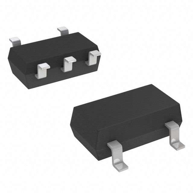
MAX6425UK46+T是Maxim Integrated推出的一款高精度电源监控器,属于PMIC中的电压监控类芯片。该器件采用微型SOT-23封装,适用于对空间要求严苛的便携式电子设备。其主要功能是在系统上电、掉电或电源异常时产生复位信号,确保微处理器或微控制器稳定启动和可靠运行。

该芯片内置4.6V阈值检测电路,具有低功耗特性(典型工作电流仅1.5μA),适合电池供电应用。其应用场景主要包括:便携式医疗设备(如血糖仪、血压计)、工业控制模块、智能传感器、消费类电子产品(如智能家居设备、可穿戴设备)以及嵌入式系统等。在这些系统中,MAX6425UK46+T用于监测主电源电压,当电压低于设定阈值时,自动触发复位信号,防止微处理器因供电不稳定而发生误操作或程序跑飞。

此外,该器件具备出色的抗噪声能力和温度稳定性,可在-40°C至+125°C的宽温范围内可靠工作,适用于严苛工业环境。其推挽输出结构无需外部上拉电阻,简化了电路设计,提高了系统集成度。综上,MAX6425UK46+T是一款高性能、小尺寸、低功耗的电压监控解决方案,广泛应用于需要高可靠性和紧凑设计的电子系统中。
| 参数 | 数值 |
| 产品目录 | 集成电路 (IC)半导体 |
| 描述 | IC MPU/RESET CIRC 4.625V SOT23-5监控电路 Single uPower Reset Circuit |
| 产品分类 | |
| 品牌 | Maxim Integrated |
| 产品手册 | |
| 产品图片 |
|
| rohs | 符合RoHS无铅 / 符合限制有害物质指令(RoHS)规范要求 |
| 产品系列 | 电源管理 IC,监控电路,Maxim Integrated MAX6425UK46+T- |
| NumberofInputsMonitored | 1 Input |
| 数据手册 | |
| 产品型号 | MAX6425UK46+T |
| 产品培训模块 | http://www.digikey.cn/PTM/IndividualPTM.page?site=cn&lang=zhs&ptm=25703http://www.digikey.cn/PTM/IndividualPTM.page?site=cn&lang=zhs&ptm=25705 |
| 产品目录页面 | |
| 产品种类 | 监控电路 |
| 人工复位 | No Manual Reset |
| 供应商器件封装 | SOT-23-5 |
| 其它名称 | MAX6425UK46+TDKR |
| 功率失效检测 | No |
| 包装 | Digi-Reel® |
| 受监控电压数 | 1 |
| 商标 | Maxim Integrated |
| 复位 | 低有效 |
| 复位超时 | 可调节/可选择 |
| 安装类型 | 表面贴装 |
| 安装风格 | SMD/SMT |
| 封装 | Reel |
| 封装/外壳 | SC-74A,SOT-753 |
| 封装/箱体 | SOT-23-5L |
| 工作温度 | -40°C ~ 125°C |
| 工作电源电流 | 2.5 uA |
| 工厂包装数量 | 2500 |
| 最大功率耗散 | 571 mW |
| 最大工作温度 | + 125 C |
| 最小工作温度 | - 40 C |
| 标准包装 | 1 |
| 欠电压阈值 | 4.509 V |
| 电压-阈值 | 4.625V |
| 电池备用开关 | No Backup |
| 电源电压-最大 | 5.5 V |
| 电源电压-最小 | 1 V |
| 监视器 | No Watchdog |
| 类型 | Voltage Supervisory |
| 系列 | MAX6425 |
| 芯片启用信号 | No Chip Enable |
| 被监测输入数 | 1 Input |
| 输出 | 开路漏极或开路集电极 |
| 输出类型 | Active Low, Open Drain |
| 过电压阈值 | 4.741 V |
| 重置延迟时间 | 4.375 ms |
| 阈值电压 | 1.6 V to 5 V |
| 零件号别名 | MAX6425 |







- 商务部:美国ITC正式对集成电路等产品启动337调查
- 曝三星4nm工艺存在良率问题 高通将骁龙8 Gen1或转产台积电
- 太阳诱电将投资9.5亿元在常州建新厂生产MLCC 预计2023年完工
- 英特尔发布欧洲新工厂建设计划 深化IDM 2.0 战略
- 台积电先进制程称霸业界 有大客户加持明年业绩稳了
- 达到5530亿美元!SIA预计今年全球半导体销售额将创下新高
- 英特尔拟将自动驾驶子公司Mobileye上市 估值或超500亿美元
- 三星加码芯片和SET,合并消费电子和移动部门,撤换高东真等 CEO
- 三星电子宣布重大人事变动 还合并消费电子和移动部门
- 海关总署:前11个月进口集成电路产品价值2.52万亿元 增长14.8%





PDF Datasheet 数据手册内容提取
Click here for production status of specific part numbers. MAX6340/MAX6421– Low-Power, SC70/SOT µP Reset Circuits MAX6426 with Capacitor-Adjustable Reset Timeout Delay General Description Benefits and Features The MAX6340/MAX6421–MAX6426 low-power micropro- ● Monitor System Voltages from 1.6V to 5V cessor supervisor circuits monitor system voltages from ● Capacitor-Adjustable Reset Timeout Period 1.6V to 5V. These devices perform a single function: they ● Low Quiescent Current (1.6µA typ) assert a reset signal whenever the VCC supply voltage falls below its reset threshold. The reset output remains ● Three RESET Output Options Push-Pull RESET asserted for the reset timeout period after VCC rises Push-Pull RESET above the reset threshold. The reset timeout is externally Open-Drain RESET set by a capacitor to provide more flexibility. The MAX6421/MAX6424 have an active-low, push- ● Guaranteed Reset Valid to VCC = 1V pull reset output. The MAX6422 has an active-high, push- ● Immune to Short VCC Transients pull reset output and the MAX6340/MAX6423/ MAX6425/ ● Small 4-Pin SC70, 4-Pin SOT143, and 5-Pin SOT23 MAX6426 have an active-low, open-drain reset output. Packages The MAX6421/MAX6422/MAX6423 are offered in 4-pin ● MAX6340 Pin Compatible with LP3470 SC70 or SOT143 packages. The MAX6340/MAX6424/ ● MAX6424/MAX6425 Pin Compatible with MAX6425/MAX6426 are available in 5-pin SOT23-5 NCP300–NCP303, MC33464/MC33465, packages. S807/S808/S809, and RN5VD Applications ● MAX6426 Pin Compatible with PST92XX ● Portable Equipment ● AEC-Q100 Qualified (MAX6340UK31/V+T) ● Battery-Powered Computers/Controllers ● Automotive ● Medical Equipment Typical Operating Circuit, Selector Guide, and Ordering Information appear at end of data sheet. ● Intelligent Instruments ● Embedded Controllers ● Critical µP Monitoring ● Set-Top Boxes ● Computers Pin Configurations TOP VIEW VCC 1 4 RESET MAX6421X (RESET) MAX6422X MAX6423X GND 2 3 SRT SC70 ( ) ARE FOR THE MAX6422 Pin Configurations continued at end of data sheet. 19-2440; Rev 10; 5/18
MAX6340/MAX6421– Low-Power, SC70/SOT µP Reset Circuits MAX6426 with Capacitor-Adjustable Reset Timeout Delay Absolute Maximum Ratings All Voltages Referenced to GND Continuous Power Dissipation (TA = +70°C) VCC .......................................................................-0.3V to +6.0V 4-Pin SC70 (derate 3.1mW/°C above +70°C) .............245mW SRT, RESET, RESET (push-pull) .............-0.3V to (VCC + 0.3V) 4-Pin SOT143 (derate 4mW/°C above +70°C) ...........320mW RESET (open drain) .............................................-0.3V to +6.0V 5-Pin SOT23 (derate 7.1mW/°C above +70°C) ..........571mW Input Current (all pins) ......................................................±20mA Operating Temperature Range .........................-40°C to +125°C Output Current (RESET, RESET) ....................................±20mA Storage Temperature Range ............................-65°C to +150°C Junction Temperature ......................................................+150°C Lead Temperature (soldering, 10s) .................................+300°C Stresses beyond those listed under “Absolute Maximum Ratings” may cause permanent damage to the device. These are stress ratings only, and functional operation of the device at these or any other conditions beyond those indicated in the operational sections of the specifications is not implied. Exposure to absolute maximum rating conditions for extended periods may affect device reliability. Electrical Characteristics (VCC = 1V to 5.5V, TA = TMIN to TMAX, unless otherwise specified. Typical values are at VCC = 5V and TA = +25°C.) (Note 1) PARAMETER SYMBOL CONDITIONS MIN TYP MAX UNITS Supply Voltage Range VCC 1.0 5.5 V VCC ≤ 5.0V 2.5 4.2 Supply Current ICC VCC ≤ 3.3V 1.9 3.4 µA VCC ≤ 2.0V 1.6 2.5 TA = +25°C VTH - 1.5% VTH + 1.5% VCC Reset Threshold Accuracy VTH V TA = -40°C to +125°C VTH - 2.5% VTH + 2.5% Hysteresis VHYST 4 x VTH mV VCC to Reset Delay tRD VCC falling at 1mV/µs 80 µs CSRT = 1500pF 3.00 4.375 5.75 Reset Timeout Period tRP ms CSRT = 0 0.275 VSRT Ramp Current IRAMP VSRT = 0 to 0.65V; VCC = 1.6V to 5V 240 nA VSRT Ramp Threshold VTH-RAMP VCC = 1.6V to 5V (VRAMP rising) 0.65 V RAMP Threshold Hysteresis VRAMP falling threshold 33 mV VCC ≥ 1.0V, ISINK = 50µA 0.3 RESET Output Voltage Low VOL VCC ≥ 2.7V, ISINK = 1.2mA 0.3 V VCC ≥ 4.5V, ISINK = 3.2mA 0.4 VCC ≥ 1.8V, ISOURCE = 200µA 0.8 x VCC RESET Output Voltage High, Push-Pull VOH VCC ≥ 2.25V, ISOURCE = 500µA 0.8 x VCC V VCC ≥ 4.5V, ISOURCE = 800µA 0.8 x VCC RESET Output Leakage Current, Open-Drain ILKG VCC > VTH, reset not asserted 1.0 µA VCC ≥ 1.0V, ISOURCE = 1µA 0.8 x VCC VCC ≥ 1.8V, ISOURCE = 150µA 0.8 x VCC RESET Output Voltage High VOH V VCC ≥ 2.7V, ISOURCE = 500µA 0.8 x VCC VCC ≥ 4.5V, ISOURCE = 800µA 0.8 x VCC VCC ≥ 1.8V, ISINK = 500µA 0.3 RESET Output Voltage Low VOL VCC ≥ 2.7V, ISINK = 1.2mA 0.3 V VCC ≥ 4.5V, ISINK = 3.2mA 0.4 Note 1: Devices production tested at +25°C. Overtemperature limits are guaranteed by design. www.maximintegrated.com Maxim Integrated │ 2
MAX6340/MAX6421– Low-Power, SC70/SOT µP Reset Circuits MAX6426 with Capacitor-Adjustable Reset Timeout Delay Typical Operating Characteristics (VCC = 5V, CSRT = 1500pF, TA = +25°C, unless otherwise noted.) SUPPLY CURRENT RESET TIMEOUT PERIOD vs. SUPPLY VOLTAGE RESET TIMEOUT PERIOD vs. CSRT vs. TEMPERATURE µSUPPLY CURRENT (A) 1122334.......0505050 TA = +25°TCA = +125°C TA = -40°C MAX6421/26 toc01 RESET TIMEOUT PERIOD (ms)101,100010010000 MAX6421/26 toc02 RESET TIMEOUT PERIOD (ms)4444....21230550 CSRT = 1500pF MAX6421/26 toc03 0.5 0 0.1 4.10 0 1 2 3 4 5 6 0.001 0.01 0.1 1 10 100 1000 -50 -25 0 25 50 75 100 125 SUPPLY VOLTAGE (V) CSRT (nF) TEMPERATURE (°C) RESET TIMEOUT PERIOD MAXIMUM TRANSIENT DURATION VCC TO RESET DELAY vs. TEMPERATURE vs. RESET THRESHOLD OVERDRIVE vs. TEMPERATURE (VCC FALLING) µRESET TIMEOUT PERIOD (s)335544650055000000000 CSRT = 0 MAX6421/26 toc04 TRANSIENT DURATION (s)1111507527005055 RABEOSEVTE OTHCEC UCRUSRVE MAX6421/26 toc05 µV TO RESET DELAY Ss)CC111111110453260000000 VCC FALLING AT 1mVs MAX6421/26 toc06 250 25 90 VTH = 2.95V 200 0 80 -50 -25 0 25 50 75 100 125 0 200 400 600 800 1000 -50 -25 0 25 50 75 100 125 TEMPERATURE (°C) RESET THRESHOLD OVERDRIVE (mV) TEMPERATURE (°C) POWER-UP/POWER-DOWN NORMALIZED RESET THRESHOLD CHARACTERISTIC vs. TEMPERATURE VCC VTH = 1.6V MAX6421/26 toc07 SHOLD11..000046 MAX6421/26 toc08 E HR1.002 1V/div T T E ES1.000 R D E ALIZ0.998 M R RESET NO0.996 1V/div 0.994 400s/div -50 -25 0 25 50 75 100 125 TEMPERATURE (°C) www.maximintegrated.com Maxim Integrated │ 3
MAX6340/MAX6421– Low-Power, SC70/SOT µP Reset Circuits MAX6426 with Capacitor-Adjustable Reset Timeout Delay Pin Description PIN MAX6421 MAX6424 MAX6340 MAX6422 MAX6426 NAME FUNCTION MAX6425 MAX6423 SOT23 SOT143 SC70 SOT23 SOT23 Set Reset Timeout Input. Connect a capacitor between SRT and ground to set the timeout period. Determine the 1 3 3 5 1 SRT period as follows: tRP = 2.73 × 10⁶ × CSRT + 275µs with tRP in seconds and CSRT in farads 2 1 2 3 2, 3 GND Ground 3 — — 4 — N.C. Not Internally Connected. Can be connected to GND 4 2 1 2 5 VCC Supply Voltage and Reset Threshold Monitor Input RESET changes from high to low whenever VCC drops below the selected reset threshold voltage. RESET 5 1 4 RESET remains low for the reset timeout period after VCC exceeds the reset threshold 4 4 RESET changes from low to high whenever VCC drops below the selected reset threshold voltage. RESET — — — RESET remains high for the reset timeout period after VCC exceeds the reset threshold Detailed Description 3.3V Reset Output The reset output is typically connected to the reset input of VCC 5.0V a µP. A µP’s reset input starts or restarts the µP in a known LASER-TRIMMED state. The MAX6340/MAX6421–MAX6426 µP superviso- RESISTORS ry circuits provide the reset logic to prevent code-execu- tion errors during power-up, power-down, and brownout conditions (see Typical Operating Characteristics). VREF 10kΩ RESET RESET changes from high to low whenever VCC drops 5V below the threshold voltage. Once VCC exceeds the SRT RESET N SYSTEM threshold voltage, RESET remains low for the capaci- TIMEOUT MAX6340 tor-adjustable reset timeout period. CSRT MAX6423 MAX6425 The MAX6422 active-high RESET output is the inverse MAX6426 GND logic of the active-low RESET output. All device outputs are guaranteed valid for VCC > 1V. The MAX6340/MAX6423/MAX6425/MAX6426 are open- Figure 1. MAX6340/MAX6423/MAX6425/MAX6426 Open-Drain drain RESET outputs. Connect an external pullup resistor RESET Output Allows Use with Multiple Supplies to any supply from 0 to 5.5V. Select a resistor value large Selecting a Reset Capacitor enough to register a logic low when RESET is asserted The reset timeout period is adjustable to accommodate and small enough to register a logic high while supply- a variety of µP applications. Adjust the reset timeout ing all input current and leakage paths connected to the RESET line. A 10kΩ to 100kΩ pullup is sufficient in most period (tRP) by connecting a capacitor (CSRT) between SRT and ground. Calculate the reset timeout capacitor applications. as follows: www.maximintegrated.com Maxim Integrated │ 4
MAX6340/MAX6421– Low-Power, SC70/SOT µP Reset Circuits MAX6426 with Capacitor-Adjustable Reset Timeout Delay CSRT = (tRP - 275µs) / (2.73 5 106) Applications Information where tRP is in seconds and CSRT is in farads. Interfacing to Other Voltages for Logic The reset delay time is set by a current/capacitor-con- Compatibility trolled ramp compared to an internal 0.65V reference. An The open-drain outputs of the MAX6340/MAX6423/ internal 240nA ramp current source charges the external MAX6425/MAX6426 can be used to interface to µPs with capacitor. The charge to the capacitor is cleared when a other logic levels. As shown in Figure 1, the open-drain reset condition is detected. Once the reset condition is output can be connected to voltages from 0 to 5.5V. This removed, the voltage on the capacitor ramps according to allows for easy logic compatibility to various µPs. the formula: dV/dt = I/C. The CSRT capacitor must ramp to Wired-OR Reset 0.65V to deassert the reset. CSRT must be a low-leakage To allow auxiliary circuitry to hold the system in reset, (<10nA) type capacitor; ceramic is recommended. an external open-drain logic signal can be connected Operating as a Voltage Detector to the open-drain RESET of the MAX6340/MAX6423/ The MAX6340/MAX6421–MAX6426 can be operated in MAX6425/MAX6426, as shown in Figure 2. This config- uration can reset the µP, but does not provide the reset a voltage detector mode by floating the SRT pin. The timeout when the external logic signal is released. reset delay times for VCC rising above or falling below the threshold are not significantly different. The reset output Negative-Going VCC Transients is deasserted smoothly without false pulses. In addition to issuing a reset to the µP during power-up, power-down, and brownout conditions, these supervisors are relatively immune to short-duration negative-go- ing transients (glitches). The graph Maximum Transient VCC Duration vs. Reset Threshold Overdrive in the Typical Operating Characteristics shows this relationship. The area below the curve of the graph is the region in VDD which these devices typically do not generate a reset 10kΩ MAX6340 pulse. This graph was generated using a negative-going MAX6423 MAX6425 pulse applied to VCC, starting above the actual reset MAX6426 µP threshold (VTH) and ending below it by the magnitude indicated (reset-threshold overdrive). As the magnitude of RESET RESET the transient decreases (farther below the reset thresh- old), the maximum allowable pulse width decreases. N Typically, a VCC transient that goes 100mV below the GND reset threshold and lasts 50µs or less does not cause a reset pulse to be issued. Ensuring a Valid RESET or RESET OPEN-DRAIN LOGIC Down to VCC = 0 When VCC falls below 1V, RESET/RESET current-sinking N (sourcing) capabilities decline drastically. In the case of the MAX6421/MAX6424, high-impedance CMOS-logic inputs connected to RESET can drift to undetermined Figure 2. Wired-OR Reset Circuit voltages. This presents no problems in most applications, since most µPs and other circuitry do not operate with VCC below 1V. In those applications where RESET must be valid down to zero, adding a pulldown resistor between RESET and ground sinks any stray leakage currents, holding RESET low (Figure 3). The value of the pulldown resis- tor is not critical; 100kΩ is large enough not to load RESET and small enough to pull RESET to ground. For applications using the MAX6422, a 100kΩ pullup resis- www.maximintegrated.com Maxim Integrated │ 5
MAX6340/MAX6421– Low-Power, SC70/SOT µP Reset Circuits MAX6426 with Capacitor-Adjustable Reset Timeout Delay Table 1. Reset Threshold Voltage Suffix VCC SUFFIX MIN TYP MAX 16 1.536 1.575 1.614 VCC 17 1.623 1.665 1.707 MAX6421 MAX6424 18 1.755 1.800 1.845 19 1.853 1.900 1.948 RESET 20 1.950 2.000 2.050 100k 21 2.048 2.100 2.153 GND 22 2.133 2.188 2.243 23 2.255 2.313 2.371 Figure 3. Ensuring RESET Valid to VCC = 0 24 2.340 2.400 2.460 25 2.438 2.500 2.563 26 2.559 2.625 2.691 VCC 27 2.633 2.700 2.768 100k 28 2.730 2.800 2.870 VCC 29 2.852 2.925 2.998 MAX6422 30 2.925 3.000 3.075 31 2.998 3.075 3.152 RESET 32 3.120 3.200 3.280 33 3.218 3.300 3.383 GND 34 3.315 3.400 3.485 35 3.413 3.500 3.558 Figure 4. Ensuring RESET Valid to VCC = 0 36 3.510 3.600 3.690 tor between RESET and VCC holds RESET high when 37 3.608 3.700 3.793 VCC falls below 1V (Figure 4). Open-drain RESET ver- 38 3.705 3.800 3.895 sions are not recommended for applications requiring 39 3.803 3.900 3.998 valid logic for VCC down to zero. 40 3.900 4.000 4.100 Layout Consideration 41 3.998 4.100 4.203 SRT is a precise current source. When developing the 42 4.095 4.200 4.305 layout for the application, be careful to minimize board 43 4.193 4.300 4.408 capacitance and leakage currents around this pin. Traces connected to SRT should be kept as short as possible. 44 4.266 4.375 4.484 Traces carrying high-speed digital signals and traces with 45 4.388 4.500 4.613 large voltage potentials should be routed as far from SRT 46 4.509 4.625 4.741 as possible. Leakage current and stray capacitance (e.g., 47 4.583 4.700 4.818 a scope probe) at this pin could cause errors in the reset timeout period. When evaluating these parts, use clean 48 4.680 4.800 4.920 prototype boards to ensure accurate reset periods. 49 4.778 4.900 5.023 50 4.875 5.000 5.125 www.maximintegrated.com Maxim Integrated │ 6
MAX6340/MAX6421– Low-Power, SC70/SOT µP Reset Circuits MAX6426 with Capacitor-Adjustable Reset Timeout Delay Standard Versions Table PART* OUTPUT STAGE PART* OUTPUT STAGE MAX6340UK16+T Open-Drain RESET MAX6423US16+T Open-Drain RESET MAX6340UK22+T Open-Drain RESET MAX6423XS16+T Open-Drain RESET MAX6340UK26+T Open-Drain RESET MAX6423US22+T Open-Drain RESET MAX6340UK29+T Open-Drain RESET MAX6423XS22+T Open-Drain RESET MAX6340UK46+T Open-Drain RESET MAX6423US26+T Open-Drain RESET MAX6421US16+T Push-Pull RESET MAX6423XS26+T Open-Drain RESET MAX6421XS16+T Push-Pull RESET MAX6423US29+T Open-Drain RESET MAX6421US22+T Push-Pull RESET MAX6423XS29+T Open-Drain RESET MAX6421XS22+T Push-Pull RESET MAX6423US46+T Open-Drain RESET MAX6421US26+T Push-Pull RESET MAX6423XS46+T Open-Drain RESET MAX6421XS26+T Push-Pull RESET MAX6424UK16+T Push-Pull RESET MAX6421US29+T Push-Pull RESET MAX6424UK22+T Push-Pull RESET MAX6421XS29+T Push-Pull RESET MAX6424UK26+T Push-Pull RESET MAX6421US46+T Push-Pull RESET MAX6424UK29+T Push-Pull RESET MAX6421XS46+T Push-Pull RESET MAX6424UK46+T Push-Pull RESET MAX6422US16+T Push-Pull RESET MAX6425UK16+T Open-Drain RESET MAX6422XS16+T Push-Pull RESET MAX6425UK22+T Open-Drain RESET MAX6422US22+T Push-Pull RESET MAX6425UK26+T Open-Drain RESET MAX6422XS22+T Push-Pull RESET MAX6425UK29+T Open-Drain RESET MAX6422US26+T Push-Pull RESET MAX6425UK46+T Open-Drain RESET MAX6422XS26+T Push-Pull RESET MAX6426UK16+T Open-Drain RESET MAX6422US29+T Push-Pull RESET MAX6426UK22+T Open-Drain RESET MAX6422XS29+T Push-Pull RESET MAX6426UK26+T Open-Drain RESET MAX6422US46+T Push-Pull RESET MAX6426UK29+T Open-Drain RESET MAX6422XS46+T Push-Pull RESET MAX6426UK46+T Open-Drain RESET *Sample stock is generally held on all standard versions. Contact Typical Operating Circuit factory for availability of nonstandard versions. VCC VCC LASER-TRIMMED RESISTORS P VREF RESET RESET SRT RESET TIMEOUT CSRT MAX6421 MAX6424 GND www.maximintegrated.com Maxim Integrated │ 7
MAX6340/MAX6421– Low-Power, SC70/SOT µP Reset Circuits MAX6426 with Capacitor-Adjustable Reset Timeout Delay Pin Configurations (continued) TOP VIEW SRT 1 5 RESET RESET 1 5 SRT MAX6340 MAX6424 GND 2 VCC 2 MAX6425 N.C. 3 4 VCC GND 3 4 N.C. SOT23 SOT23 GND 1 4 RESET SRT 1 5 VCC MAX6421U (RESET) MAX6422U MAX6426 MAX6423U GND 2 VCC 2 3 SRT GND 3 4 RESET SOT143 SOT23 Selector Guide PART PUSH-PULL RESET PUSH-PULL RESET OPEN-DRAIN RESET PIN-PACKAGE MAX6340 — — ✔ 5 SOT23 MAX6421 ✔ — — 4 SOT143/SC70 MAX6422 — ✔ — 4 SOT143/SC70 MAX6423 — — ✔ 4 SOT143/SC70 MAX6424 ✔ — — 5 SOT23 MAX6425 — — ✔ 5 SOT23 MAX6426 — — ✔ 5 SOT23 www.maximintegrated.com Maxim Integrated │ 8
MAX6340/MAX6421– Low-Power, SC70/SOT µP Reset Circuits MAX6426 with Capacitor-Adjustable Reset Timeout Delay Ordering Information Package Information PART TEMP RANGE PIN-PACKAGE For the latest package outline information and land patterns (footprints), go to www.maximintegrated.com/packages. Note MAX6340UK_ _+T -40°C to +125°C 5 SOT23-5 that a “+”, “#”, or “-” in the package code indicates RoHS status MAX6340UK_ _/V+T -40°C to +125°C 5 SOT23-5 only. Package drawings may show a different suffix character, but MAX6340UK31/V+T -40°C to +125°C 5 SOT23-5 the drawing pertains to the package regardless of RoHS status. MAX6421XS_ _+T -40°C to +125°C 4 SC70-4 PACKAGE PACKAGE OUTLINE LAND MAX6421US_ _+T -40°C to +125°C 4 SOT143-4 TYPE CODE NO. PATTERN NO. MAX6421US_ _-T -40°C to +125°C 4 SOT143-4 4 SC70 X4+1 21-0098 90-0187 MAX6422XS_ _+T -40°C to +125°C 4 SC70-4 4 SOT143 U4+1 21-0052 90-0183 MAX6422US_ _+T -40°C to +125°C 4 SOT143-4 5 SOT23 U5+2 21-0057 90-0174 MAX6422US_ _-T -40°C to +125°C 4 SOT143-4 MAX6423XS_ _+T -40°C to +125°C 4 SC70-4 MAX6423US_ _+T -40°C to +125°C 4 SOT143-4 MAX6423US_ _-T -40°C to +125°C 4 SOT143-4 MAX6424UK_ _+T -40°C to +125°C 5 SOT23-5 MAX6424UK_ _-T -40°C to +125°C 5 SOT23-5 MAX6425UK_ _+T -40°C to +125°C 5 SOT23-5 MAX6425UK_ _-T -40°C to +125°C 5 SOT23-5 MAX6426UK_ _+T -40°C to +125°C 5 SOT23-5 Note: The MAX6340/MAX6421–MAX6426 are available with factory-trimmed reset thresholds from 1.575V to 5.0V in approximately 0.1V increments. Insert the desired nominal reset threshold suffix (from Table 1) into the blanks. There are 50 standard versions with a required order increment of 2500 pieces. Sample stock is generally held on standard versions only (see Standard Versions Table). Required order increment is 10,000 pieces for nonstandard versions. Contact factory for availability. All devices are available in tape-and-reel only. Devices are available in both leaded and lead-free packaging. “+” Denotes Lead(Pb)-free packages and “-” denotes leaded packages. For top mark information, please go to https://www.maximinte- grated.com/en/design/packaging/topmark/ Chip Information TRANSISTOR COUNT: 295 PROCESS: BiCMOS www.maximintegrated.com Maxim Integrated │ 9
MAX6340/MAX6421– Low-Power, SC70/SOT µP Reset Circuits MAX6426 with Capacitor-Adjustable Reset Timeout Delay Revision History REVISION REVISION PAGES DESCRIPTION NUMBER DATE CHANGED 5 3/14 Added /V OPN to Ordering Information 1 Added lead-free part numbers to Ordering Information table and removed top 6 12/15 1, 8 mark information from Standard Versions table Changed MAX6340UK_ _/V-T to MAX6340UK_ _/V+T in Ordering 7 1/16 9 Information table 8 9/16 Updated Table 1 6 9 3/18 Updated Ordering Information table 9 10 5/18 Updated Benefits and Features section 1 For pricing, delivery, and ordering information, please contact Maxim Direct at 1-888-629-4642, or visit Maxim Integrated’s website at www.maximintegrated.com. Maxim Integrated cannot assume responsibility for use of any circuitry other than circuitry entirely embodied in a Maxim Integrated product. No circuit patent licenses are implied. Maxim Integrated reserves the right to change the circuitry and specifications without notice at any time. The parametric values (min and max limits) shown in the Electrical Characteristics table are guaranteed. Other parametric values quoted in this data sheet are provided for guidance. Maxim Integrated and the Maxim Integrated logo are trademarks of Maxim Integrated Products, Inc. © 2018 Maxim Integrated Products, Inc. │ 10
Mouser Electronics Authorized Distributor Click to View Pricing, Inventory, Delivery & Lifecycle Information: M axim Integrated: MAX6421US26+T MAX6423US26+T MAX6423XS26+T MAX6425UK26+T MAX6421XS36+T MAX6424UK21+T MAX6422US30+T MAX6421XS49+T MAX6340UK48+T MAX6425UK49+T MAX6422XS48+T MAX6422XS28+T MAX6340UK29/V+T MAX6340UK16+T MAX6340UK17+T MAX6340UK18+T MAX6340UK19+T MAX6340UK20+T MAX6340UK21+T MAX6340UK22+T MAX6340UK23+T MAX6340UK24+T MAX6340UK25+T MAX6340UK26+T MAX6340UK27+T MAX6340UK28+T MAX6340UK29+T MAX6340UK30+T MAX6340UK31+T MAX6340UK32+T MAX6340UK33+T MAX6340UK34+T MAX6340UK35+T MAX6340UK36+T MAX6340UK37+T MAX6340UK38+T MAX6340UK39+T MAX6340UK40+T MAX6340UK41+T MAX6340UK42+T MAX6340UK43+T MAX6340UK44+T MAX6340UK45+T MAX6340UK46+T MAX6340UK47+T MAX6340UK49+T MAX6340UK50+T MAX6421US16+T MAX6421US17+T MAX6421US18+T MAX6421US19+T MAX6421US20+T MAX6421US21+T MAX6421US22+T MAX6421US23+T MAX6421US24+T MAX6421US25+T MAX6421US27+T MAX6421US28+T MAX6421US29+T MAX6421US30+T MAX6421US31+T MAX6421US32+T MAX6421US33+T MAX6421US34+T MAX6421US35+T MAX6421US36+T MAX6421US37+T MAX6421US38+T MAX6421US39+T MAX6421US40+T MAX6421US41+T MAX6421US42+T MAX6421US43+T MAX6421US44+T MAX6421US45+T MAX6421US46+T MAX6421US47+T MAX6421US48+T MAX6421US49+T MAX6421US50+T MAX6421XS16+T MAX6421XS17+T MAX6421XS18+T MAX6421XS19+T MAX6421XS20+T MAX6421XS21+T MAX6421XS22+T MAX6421XS23+T MAX6421XS24+T MAX6421XS25+T MAX6421XS26+T MAX6421XS27+T MAX6421XS28+T MAX6421XS29+T MAX6421XS30+T MAX6421XS31+T MAX6421XS32+T MAX6421XS33+T MAX6421XS34+T