ICGOO在线商城 > MAX5732AUTN+

 Datasheet下载
- 型号: MAX5732AUTN+
- 制造商: Maxim
- 库位|库存: xxxx|xxxx
- 要求:
| 数量阶梯 | 香港交货 | 国内含税 |
| +xxxx | $xxxx | ¥xxxx |
查看当月历史价格
查看今年历史价格
MAX5732AUTN+产品简介:
ICGOO电子元器件商城为您提供MAX5732AUTN+由Maxim设计生产,在icgoo商城现货销售,并且可以通过原厂、代理商等渠道进行代购。 提供MAX5732AUTN+价格参考以及MaximMAX5732AUTN+封装/规格参数等产品信息。 你可以下载MAX5732AUTN+参考资料、Datasheet数据手册功能说明书, 资料中有MAX5732AUTN+详细功能的应用电路图电压和使用方法及教程。
MAXIM INTEGRATED的MAX5732AUTN+是一款低功耗、16位、串行输入、电压输出数模转换器(DAC),广泛应用于对精度和稳定性要求较高的场合。其典型应用场景包括工业自动化控制系统,如PLC模块、过程控制仪表,用于精确调节模拟信号输出;便携式测试与测量设备,得益于其低功耗特性,适合电池供电系统;精密仪器仪表,如数据采集系统、传感器校准设备,可提供高分辨率的模拟输出;通信系统中的偏置控制或信号调节电路;以及医疗设备中需要稳定模拟信号输出的模块。该器件具备±1 LSB积分非线性(INL)和优异的长期稳定性,支持单通道电压输出,内置输出缓冲放大器,可直接驱动容性负载,简化了外围设计。采用小型10引脚TDFN封装,节省PCB空间,适用于紧凑型设计。工作温度范围宽(-40°C至+125°C),适应严苛环境,是高精度模拟控制应用的理想选择。
| 参数 | 数值 |
| 产品目录 | 集成电路 (IC)半导体 |
| 描述 | IC DAC 16BIT 32CHAN SER 56-TQFN数模转换器- DAC 10-Bit 32Ch Precision DAC |
| 产品分类 | |
| 品牌 | Maxim Integrated |
| 产品手册 | |
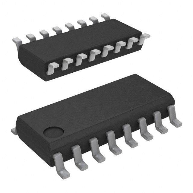
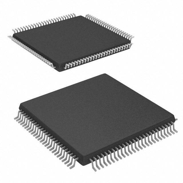
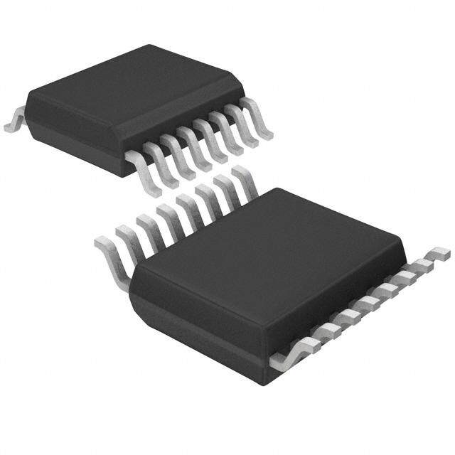
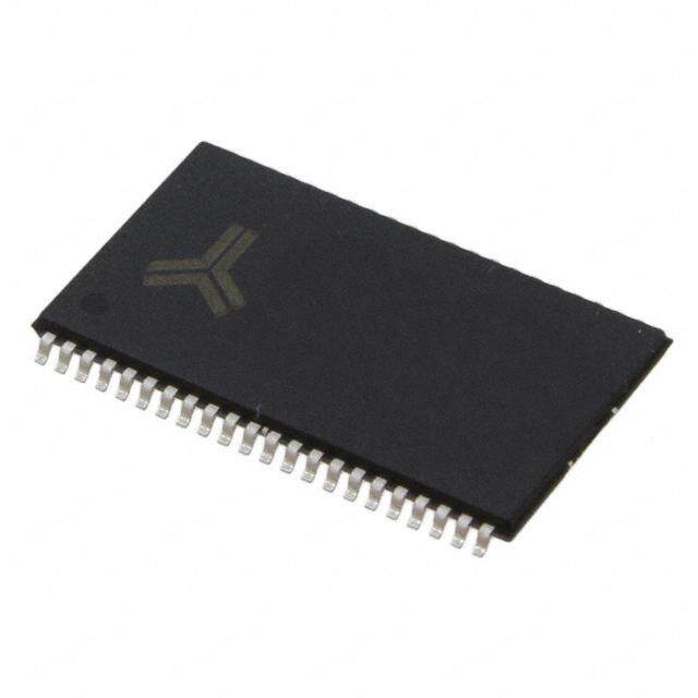
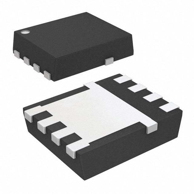
| 产品图片 |
|
| rohs | 符合RoHS无铅 / 符合限制有害物质指令(RoHS)规范要求 |
| 产品系列 | 数据转换器IC,数模转换器- DAC,Maxim Integrated MAX5732AUTN+- |
| 数据手册 | |
| 产品型号 | MAX5732AUTN+ |
| 产品培训模块 | http://www.digikey.cn/PTM/IndividualPTM.page?site=cn&lang=zhs&ptm=25703http://www.digikey.cn/PTM/IndividualPTM.page?site=cn&lang=zhs&ptm=25705 |
| 产品种类 | 数模转换器- DAC |
| 位数 | 16 |
| 供应商器件封装 | 56-TQFN (8x8) |
| 分辨率 | 16 bit |
| 包装 | 管件 |
| 商标 | Maxim Integrated |
| 安装类型 | 表面贴装 |
| 安装风格 | SMD/SMT |
| 封装 | Tube |
| 封装/外壳 | 56-WFQFN 裸露焊盘 |
| 封装/箱体 | TQFN-EP-56 |
| 工作温度 | 0°C ~ 85°C |
| 工厂包装数量 | 37 |
| 应用说明 | |
| 建立时间 | 20µs |
| 接口类型 | QSPI, SPI, Serial (3-Wire, Microwire) |
| 数据接口 | MICROWIRE™,QSPI™,串行,SPI™ |
| 最大工作温度 | + 85 C |
| 最小工作温度 | 0 C |
| 标准包装 | 1 |
| 电压参考 | External |
| 电压源 | 模拟和数字 |
| 电源电压-最大 | 5.25 V |
| 电源电压-最小 | 4.75 V |
| 积分非线性 | +/- 8 LSB |
| 稳定时间 | 20 us |
| 系列 | MAX5732A |
| 结构 | Pipelined |
| 转换器数 | 32 |
| 转换器数量 | 32 |
| 输出数和类型 | 32 电压,单极 |
| 输出类型 | Voltage |
| 采样率(每秒) | * |
| 零件号别名 | MAX5732A |





- 商务部:美国ITC正式对集成电路等产品启动337调查
- 曝三星4nm工艺存在良率问题 高通将骁龙8 Gen1或转产台积电
- 太阳诱电将投资9.5亿元在常州建新厂生产MLCC 预计2023年完工
- 英特尔发布欧洲新工厂建设计划 深化IDM 2.0 战略
- 台积电先进制程称霸业界 有大客户加持明年业绩稳了
- 达到5530亿美元!SIA预计今年全球半导体销售额将创下新高
- 英特尔拟将自动驾驶子公司Mobileye上市 估值或超500亿美元
- 三星加码芯片和SET,合并消费电子和移动部门,撤换高东真等 CEO
- 三星电子宣布重大人事变动 还合并消费电子和移动部门
- 海关总署:前11个月进口集成电路产品价值2.52万亿元 增长14.8%



PDF Datasheet 数据手册内容提取
19-3148; Rev 7; 11/05 EVAALVUAAILTAIOBNL EKIT 32-Channel, 16-Bit, Voltage-Output DACs with Serial Interface General Description Features M The MAX5732–MAX5735 are 32-channel, 16-bit, voltage- ♦ Guaranteed Monotonic to 16 Bits A output, digital-to-analog converters (DACs). All devices ♦ 32 Individual DACs in an 8mm x 8mm, 56-Pin, X accept a 3V external reference input. The devices Thin QFN Package or 64-Pin TQFP Package include an internal offset DAC that allows all the outputs ♦ Four Output Voltage Ranges 5 to be offset and a ground-sensing function, allowing out- 0 to +5V (MAX5732) 7 put voltages to be referenced to a remote ground. 0 to +10V (MAX5733) 3 A 33MHz SPI™-/QSPI™-/MICROWIRE™- and digital -2.5V to +7.5V (MAX5734) 2 signal processor (DSP)-compatible serial interface con- -5V to +5V (MAX5735) – trols the MAX5732–MAX5735. Each DAC has a double- ♦ Buffered Voltage Outputs Capable of Driving M buffered input structure that helps minimize the digital 10kΩ|| 100pF noise feedthrough from the digital inputs to the outputs, ♦ Glitch-Free Power-Up A and allows for synchronous or asynchronous updating ♦ SPI-/QSPI-/MICROWIRE-/DSP-Compatible 33MHz X of the outputs. The MAX5732–MAX5735 also provide a Serial Interface DOUT that allows for read-back or daisy chaining multi- 5 ple devices. The devices provide separate power 7 Ordering Information inputs for the analog and digital sections and provide 3 separate power inputs for the output buffer amplifiers. 5 The MAX5732–MAX5735 include proprietary deglitch OUTPUT MAX PIN- PKG circuits to prevent output glitches at power-up and PART VOLTAGE INL PACKAGE CODE eliminate the need for power sequencing. The devices (V) (LSB) provide a software-shutdown mode to allow efficient 56 Thin power management. The MAX5732–MAX5735 con- MAX5732AUTN 0 to +5 ±8 T5688-3 QFN-EP* sume 50µA of supply current in shutdown. 56 Thin The MAX5732–MAX5735 provide buffered outputs that MAX5732BUTN 0 to +5 ±16 T5688-3 can drive 10kΩin parallel with 100pF. The MAX5732 has QFN-EP* a 0 to +5V output range; the MAX5733 has a 0 to +10V Note:All devices operate over the 0°C to +85°C temperature range; the MAX5734 has a -2.5V to +7.5V range; the range. MAX5735 has a -5V to +5V range. The MAX5732– *EP = Exposed pad (internally connected to VSS). MAX5735 are available in a 56-pin, 8mm x 8mm, thin QFN package and 64-pin TQFP package and operate Ordering Information continued at end of data sheet. over the 0°C to +85°C temperature range. Pin Configurations Applications Automatic Test Systems TOP VIEW Optical Router Controls AVCCOUT21 OUT22 VSSAGND OUT23 OUT24 OUT25 OUT26OUT27 OUT28 OUT29 OUT30 OUT31 42 41 40 39 38 37 36 35 34 33 32 31 30 29 Industrial Process Controls OUT20 43 28 VSS Arbitrary Function Generators OUT19 44 27 AVDD OUT18 45 26 REF Avionics Equipment OUT17 46 25 REFGND OUT16 47 24 GS Digital Offset/Gain Adjustment AVCC 48 23 CLR REFGND 49 22 LDAC AVDD 50 MAX5732–MAX5735 21 DGND OUT15 51 20 DVDD OUT14 52 19 DIN OUT13 53 18 SCLK OUT12 54 17 DOUT OUT11 55 16 CS SPI/QSPI are trademarks of Motorola, Inc. EXPOSED PADDLE OUT10 56 15 DSP MICROWIRE is a trademark of National Semiconductor Corp. 1 2 3 4 5 6 7 8 9 10 11 12 13 14 AVCCOUT9 OUT8 OUT7 N.C. OUT6OUT5 OUT4 AGND OUT3 VSSOUT2 OUT1 OUT0 Pin Configurations continued at end of data sheet. 8mm x 8mm THIN QFN-EP ________________________________________________________________Maxim Integrated Products 1 For pricing, delivery, and ordering information,please contact Maxim/Dallas Direct!at 1-888-629-4642, or visit Maxim’s website at www.maxim-ic.com.
32-Channel, 16-Bit, Voltage-Output DACs with Serial Interface 5 ABSOLUTE MAXIMUM RATINGS 3 AVCCto VSS, AGND, DGND, REFGND..................-0.3V to +12V Maximum Current into REF...............................................±10mA 7 VSSto AGND, DGND................................................-6V to +0.3V Maximum Current into Any Pin.........................................±50mA 5 AVDD, DVDDto AGND, DGND, REFGND.................-0.3V to +6V Continuous Power Dissipation (TA= +70°C) AGND to DGND.....................................................-0.3V to +0.3V Thin QFN (derate 31.3mW/°C above +70°C)...................2.5W X REF to AGND, DGND, TQFP (derate 25mW/°C above +70°C)............................2.0W A REFGND...............-0.3V to the lower of (AVDD+ 0.3V) and +6V Operating Temperature Ranges REFGND to AGND.................................................-0.3V to +0.3V MAX573__UCB...................................................0°C to +85°C M Digital Inputs to AGND, DGND, Junction Temperature......................................................+150°C REFGND..............-0.3V to the lower of (DVDD+ 0.3V) and +6V Storage Temperature Range.............................-65°C to +150°C – DOUT to DGND.......-0.3V to the lower of (DVDD+ 0.3V) and +6V Lead Temperature (soldering, 10s).................................+300°C 2 OUT_ to VSS.........-0.3V to the lower of (AVCC+ 0.3V) and+12V 3 GS to AGND................................................................-1V to +1V 7 Stresses beyond those listed under “Absolute Maximum Ratings” may cause permanent damage to the device. These are stress ratings only, and functional 5 operation of the device at these or any other conditions beyond those indicated in the operational sections of the specifications is not implied. Exposure to X absolute maximum rating conditions for extended periods may affect device reliability. A ELECTRICAL CHARACTERISTICS—MAX5732 (0 to +5V Output Voltage Range) M (AVCC= +5.25V to +5.5V (Note 1), AVDD= +5V ±5%, DVDD= +2.7V to AVDD, VSS= AGND = DGND = REFGND = GS = 0, VREF= +3.0V, RL= ∞, CL= 50pF referenced to ground, TA = TMINto TMAX, unless otherwise noted. Typical values are at TA= +25°C.) PARAMETER SYMBOL CONDITIONS MIN TYP MAX UNITS DC CHARACTERISTICS Resolution N 16 Bits MAX5732A ±4 ±8 Integral Nonlinearity (Note 2) INL LSB MAX5732B ±8 ±16 Differential Nonlinearity DNL Guaranteed monotonic (Note 3) ±1 LSB Zero-Scale Error VOS VSS = -0.5V, AVCC = +5.25V (Note 4) ±8 ±40 mV Full-Scale Error (Note 4) ±8 ±50 mV Gain Error ±0.1 ±0.5 %FSR ppm Gain Temperature Coefficient 20 FSR/°C DC Crosstalk VSS = -0.5V, AVCC = +5V (Note 5) 50 250 µV DYNAMIC CHARACTERISTICS Output-Voltage Settling Time Full-scale change to ±0.5 LSB 20 µs Voltage-Output Slew Rate 1 V/µs Digital Feedthrough (Note 6) 5 nV-s Digital Crosstalk (Note 7) 5 nV-s Digital-to-Analog Glitch Impulse Major carry transition 120 nV-s DAC-to-DAC Crosstalk (Note 8) 15 nV-s Output Noise Spectral Density at Full-scale code 250 nV/√Hz 1kHz ANALOG OUTPUTS (OUT0 to OUT31) Output Voltage Range VSS = -0.5V, AVCC = +5.25V (Note 1) 0 5 V Resistive Load to Ground 10 50 kΩ 2 _______________________________________________________________________________________
32-Channel, 16-Bit, Voltage-Output DACs with Serial Interface ELECTRICAL CHARACTERISTICS—MAX5732 (0 to +5V Output Voltage Range) (continued) M (AVCC= +5.25V to +5.5V (Note 1), AVDD= +5V ±5%, DVDD= +2.7V to AVDD, VSS= AGND = DGND = REFGND = GS = 0, VREF= A +3.0V, RL= ∞, CL= 50pF referenced to ground, TA = TMINto TMAX, unless otherwise noted. Typical values are at TA= +25°C.) X PARAMETER SYMBOL CONDITIONS MIN TYP MAX UNITS 5 Capacitive Load to Ground 50 100 pF 7 DC Output Impedance 0.1 Ω 3 Sourcing, full-scale code, output connected 5 2 to AGND Short-Circuit Current mA – Sinking, zero-scale code, output connected M -5 to AVCC A GROUND-SENSE ANALOG INPUT (GS) X Input Voltage Range VGS Relative to AGND -0.5 +0.5 V 5 GS Gain AGS 0.995 1.000 1.005 V/V 7 Input Resistance -0.5V ≤ VGS ≤ +0.5V, VSS = -0.5V 35 kΩ 3 REFERENCE INPUT (REF) 5 Input Resistance 1 MΩ Reference Input Voltage Range VREF Referred to REFGND 2.900 3.000 3.100 V DIGITAL INPUTS (CS, SCLK, DIN, LDAC, CLR, DSP) 0.7 × DVDD = +2.7V to +3.6V Input-Voltage High VIH DVDD V DVDD = +4.75V to +5.25V 2.4 Input-Voltage Low VIL 0.8 V Input Capacitance CIN 10 pF Input Current IIN Digital inputs = 0 or DVDD ±1 µA POWER REQUIREMENTS (AVCC, VSS, AGND, AVDD, DVDD, DGND) Output-Amplifier Positive Supply AVCC (Note 1) 4.75 5.50 V Voltage Output-Amplifier Negative Supply VSS -0.5 0 V Voltage Output-Amplifier Supply Voltage AVCC - VSS 5.75 V Difference Analog Supply Voltage AVDD 4.75 5.25 V Digital Supply Voltage DVDD 2.70 5.25 V VOUT0 through VOUT31 = 0 10 15 mA Analog Supply Current AIDD Software shutdown 10 µA VIH = DVDD, VIL = 0, fSCLK = 20MHz 2.5 3.5 Digital Supply Current DIDD mA VIH = +2.4V, VIL = +0.8V, fSCLK = 20MHz 5 6.5 Output-Amplifier Positive Supply VOUT0 through VOUT31 = 0 4 10 mA AICC Current Software shutdown 20 µA Output-Amplifier Negative Supply VOUT0 through VOUT31 = 0 -4 -10 mA ISS VSS = -0.5V Current Software shutdown -20 µA Power-Supply Rejection Ratio PSRR -95 dB _______________________________________________________________________________________ 3
32-Channel, 16-Bit, Voltage-Output DACs with Serial Interface 5 ELECTRICAL CHARACTERISTICS—MAX5733 (0 to +10V Output Voltage Range) 3 (AVCC = +10.5V to +11V, AVDD = 5V ±5%, DVDD = +2.7V to AVDD, VSS = AGND = DGND = REFGND = GS = 0, VREF = +3.0V, 7 RL= ∞, CL= 50pF referenced to ground, TA= TMINto TMAX, unless otherwise noted. Typical values are at TA= +25°C.) 5 PARAMETER SYMBOL CONDITIONS MIN TYP MAX UNITS X DC CHARACTERISTICS A Resolution N 16 Bits M MAX5733A ±4 ±8 Integral Nonlinearity (Note 2) INL LSB MAX5733B ±8 ±16 – 2 Differential Nonlinearity DNL Guaranteed monotonic (Note 3) ±1 LSB 3 Zero-Scale Error VOS VSS = -0.5V, AVCC = +10V (Note 4) ±8 ±40 mV 7 Full-Scale Error (Note 4) ±8 ±50 mV 5 Gain Error ±0.1 ±0.5 % FSR X ppm Gain Temperature Coefficient 20 A FSR/°C M DC Crosstalk VSS = -0.5V, AVCC = +10V (Note 5) 50 250 µV DYNAMIC CHARACTERISTICS Output-Voltage Settling Time Full-scale change to ±0.5 LSB 20 µs Voltage-Output Slew Rate 1 V/µs Digital Feedthrough (Note 6) 5 nV-s Digital Crosstalk (Note 7) 5 nV-s Digital-to-Analog Glitch Impulse Major carry transition 120 nV-s DAC-to-DAC Crosstalk (Note 8) 15 nV-s Output Noise Spectral Density at Full-scale code 250 nV/√Hz 1kHz ANALOG OUTPUTS (OUT0 to OUT31) Output Voltage Range VSS = -0.5V, AVCC = +10.5V (Note 1) 0 10 V Resistive Load to Ground 10 50 kΩ Capacitive Load to Ground 50 100 pF DC Output Impedance 0.1 Ω Sourcing, full scale, output connected to 5 AGND Short-Circuit Current mA Sinking, zero scale, output connected to -5 AVCC GROUND-SENSE ANALOG INPUT (GS) Input Voltage Range VGS Relative to AGND -0.5 +0.5 V GS Gain AGS 0.995 1.000 1.005 V/V Input Resistance -0.5V ≤ VGS ≤ +0.5V, VSS = -0.5V 70 kΩ REFERENCE INPUT (REF) Input Resistance 1 MΩ Reference Input Voltage Range VREF Referred to REFGND 2.900 3.000 3.100 V 4 _______________________________________________________________________________________
32-Channel, 16-Bit, Voltage-Output DACs with Serial Interface ELECTRICAL CHARACTERISTICS—MAX5733 (0 to +10V Output Voltage Range) (continued) M (AVCC = +10.5V to +11V, AVDD = 5V ±5%, DVDD = +2.7V to AVDD, VSS = AGND = DGND = REFGND = GS = 0, VREF = +3.0V, A RL= ∞, CL= 50pF referenced to ground, TA= TMINto TMAX, unless otherwise noted. Typical values are at TA= +25°C.) X PARAMETER SYMBOL CONDITIONS MIN TYP MAX UNITS 5 DIGITAL INPUTS (CS, SCLK, DIN, LDAC, CLR, DSP) 7 0.7 × DVDD = +2.7V to +3.6V 3 Input-Voltage High VIH DVDD V 2 DVDD = +4.75V to +5.25V 2.4 – Input-Voltage Low VIL 0.8 V M Input Capacitance CIN 10 pF A Input Current IIN Digital inputs = 0 or DVDD ±1 µA X POWER REQUIREMENTS (AVCC, VSS, AGND, AVDD, DVDD, DGND) 5 Output-Amplifier Positive Supply AVCC (Note 1) 10 11 V 7 Voltage 3 Output-Amplifier Negative Supply VSS -0.5 0 V 5 Voltage Output-Amplifier Supply Voltage AVCC - VSS 11 V Difference Analog Supply Voltage AVDD 4.75 5.25 V Digital Supply Voltage DVDD 2.70 5.25 V VOUT0 through VOUT31 = 0 10 15 mA Analog Supply Current AIDD Software shutdown 10 µA VIH = DVDD, VIL = 0, fSCLK = 20MHz 2.5 3.5 Digital Supply Current DIDD mA VIH = +2.4V, VIL = +0.8V, fSCLK = 20MHz 5 6.5 Output-Amplifier Positive Supply VOUT0 through VOUT31 = 0 4 10 mA AICC Current Software shutdown 20 µA Output-Amplifier Negative Supply VOUT0 through VOUT31 = 0 -4 -10 mA ISS VSS = -0.5V Current Software shutdown -20 µA Power-Supply Rejection Ratio PSRR -95 dB _______________________________________________________________________________________ 5
32-Channel, 16-Bit, Voltage-Output DACs with Serial Interface 5 ELECTRICAL CHARACTERISTICS—MAX5734 (-2.5V to +7.5V Output Voltage Range) 3 (AVCC= +7.75V to +8.25V, AVDD= +5V ±5%, DVDD= +2.7V to AVDD, VSS= -2.75V to -3.25V, AGND = DGND = REFGND = GS = 0, 7 program the offset DAC to 4000hex. VREF = +3.0V, RL = ∞, CL= 50pF referenced to ground, TA = TMIN to TMAX, unless otherwise noted. Typical values are at TA= +25°C.) 5 X PARAMETER SYMBOL CONDITIONS MIN TYP MAX UNITS A DC CHARACTERISTICS Resolution N 16 Bits M MAX5734A ±4 ±8 – Integral Nonlinearity (Note 2) INL LSB MAX5734B ±8 ±16 2 Differential Nonlinearity DNL Guaranteed monotonic (Note 3) ±1 LSB 3 7 Zero-Scale Error VOS VSS = -3.25V, AVCC = +7.75V (Note 4) ±8 ±40 mV Full-Scale Error (Note 4) ±8 ±50 mV 5 X Gain Error ±0.1 ±0.5 %FSR A Gain Temperature Coefficient 20 ppm FSR/°C M DC Crosstalk VSS = -3.25V, AVCC = +7.75V (Note 4) 50 250 µV DYNAMIC CHARACTERISTICS Output-Voltage Settling Time Full-scale change to ±0.5 LSB 20 µs Voltage-Output Slew Rate 1 V/µs Digital Feedthrough (Note 6) 5 nV-s Digital Crosstalk (Note 7) 5 nV-s Digital-to-Analog Glitch Impulse Major carry transition 120 nV-s DAC-to-DAC Crosstalk (Note 8) 15 nV-s Output Noise Spectral Density at Full-scale code 250 nV/√Hz 1kHz ANALOG OUTPUTS (OUT0 to OUT31) Output Voltage Range VSS = -2.75V, AVCC = +7.75V (Note 1) -2.5 +7.5 V Resistive Load to Ground 10 50 kΩ Capacitive Load to Ground 50 100 pF DC Output Impedance 0.1 Ω Sourcing, full scale, output connected to 5 AGND Short-Circuit Current mA Sinking, zero scale, output connected to -5 AVCC GROUND-SENSE ANALOG INPUT (GS) Input Voltage Range VGS Relative to AGND -0.5 +0.5 V GS Gain AGS 0.995 1.000 1.005 V/V Input Resistance -0.5V ≤ VGS ≤ +0.5V, VSS = -0.5V 70 kΩ REFERENCE INPUT (REF) Input Resistance 1 MΩ Reference Input Voltage Range VREF Referred to REFGND 2.900 3.000 3.100 V 6 _______________________________________________________________________________________
32-Channel, 16-Bit, Voltage-Output DACs with Serial Interface ELECTRICAL CHARACTERISTICS—MAX5734 (-2.5V to +7.5V Output Voltage Range) M (continued) A (AVCC= +7.75V to +8.25V, AVDD= +5V ±5%, DVDD= +2.7V to AVDD, VSS= -2.75V to -3.25V, AGND = DGND = REFGND = GS = 0, X program the offset DAC to 4000hex. VREF = +3.0V, RL = ∞, CL= 50pF referenced to ground, TA = TMIN to TMAX, unless otherwise noted. Typical values are at TA= +25°C.) 5 PARAMETER SYMBOL CONDITIONS MIN TYP MAX UNITS 7 3 DIGITAL INPUTS (CS, SCLK, DIN, LDAC, CLR, DSP) 2 0.7 × DVDD = +2.7V to +3.6V – Input-Voltage High VIH DVDD V M DVDD = +4.75V to +5.25V 2.4 A Input-Voltage Low VIL 0.8 V Input Capacitance CIN 10 pF X Input Current IIN Digital inputs = 0 or DVDD ±1 µA 5 POWER REQUIREMENTS (AVCC, VSS, AGND, AVDD, DVDD, DGND) 7 3 Output-Amplifier Positive Supply Voltage AVCC (Note 1) 7.50 8.25 V 5 Output-Amplifier Negative Supply VSS -3.25 -2.50 V Voltage Output-Amplifier Supply Voltage AVCC - VSS 11 V Difference Analog Supply Voltage AVDD 4.75 5.25 V Digital Supply Voltage DVDD 2.70 5.25 V VOUT0 through VOUT31 = 0 10 15 mA Analog Supply Current AIDD Software shutdown 10 µA VIH = DVDD, VIL = 0, fSCLK = 20MHz 2.5 3.5 Digital Supply Current DIDD mA VIH = +2.4V, VIL = +0.8V, fSCLK = 20MHz 5 6.5 Output-Amplifier Positive Supply VOUT0 through VOUT31 = 0 4 10 mA AICC Current Software shutdown 20 µA Output-Amplifier Negative Supply VOUT0 through VOUT31 = 0 -4 -10 mA ISS VSS = -2.75V Current Software shutdown -20 µA Power-Supply Rejection Ratio PSRR -95 dB _______________________________________________________________________________________ 7
32-Channel, 16-Bit, Voltage-Output DACs with Serial Interface 5 ELECTRICAL CHARACTERISTICS—MAX5735 (-5V to +5V Output Voltage Range) 3 (AVCC= +5.25V to +5.5V, AVDD= +5V ±5%, DVDD= +2.7V to AVDD, VSS= -5.25V to -5.5V, AGND = DGND = REFGND = GS = 0, 7 program the offset DAC to 8000hex. VREF= +3.0V, RL= ∞, CL= 50pF referenced to ground, TA= TMINto TMAX, unless otherwise 5 noted. Typical values are at TA = +25°C.) X PARAMETER SYMBOL CONDITIONS MIN TYP MAX UNITS A DC CHARACTERISTICS M Resolution N 16 Bits MAX5735A ±4 ±8 – Integral Nonlinearity (Note 2) INL LSB MAX5735B ±8 ±16 2 3 Differential Nonlinearity DNL Guaranteed monotonic (Note 3) ±1 LSB 7 Zero-Scale Error VOS VSS = -5.25V, AVCC = +5.25V (Note 4) ±8 ±40 mV 5 Full-Scale Error (Note 4) ±8 ±50 mV X Gain Error ±0.1 ±0.5 %FSR A ppm Gain Temperature Coefficient 20 FSR/°C M DC Crosstalk VSS = -5.75V, AVCC = +5.25V (Note 5) 50 250 µV DYNAMIC CHARACTERISTICS Output-Voltage Settling Time Full-scale change to ±0.5 LSB 20 µs Voltage-Output Slew Rate 1 V/µs Digital Feedthrough (Note 6) 5 nV-s Digital Crosstalk (Note 7) 5 nV-s Digital-to-Analog Glitch Impulse Major carry transition 120 nV-s DAC-to-DAC Crosstalk (Note 8) 15 nV-s Output Noise Spectral Density at Full-scale code 250 nV/√Hz 1kHz ANALOG OUTPUTS (OUT0 through OUT31) Output Voltage Range VSS = -5.25V, AVCC = +5.25V (Note 1) -5 +5 V Resistive Load to Ground 10 50 kΩ Capacitive Load to Ground 50 100 pF DC Output Impedance 0.1 Ω Sourcing, full scale, output connected to 5 AGND Short-Circuit Current mA Sinking, zero scale, output connected to -5 AVCC GROUND-SENSE ANALOG INPUT (GS) Input Voltage Range VGS Relative to AGND -0.5 +0.5 V GS Gain AGS 0.995 1.000 1.005 V/V Input Resistance -0.5V ≤ VGS ≤ +0.5V, VSS = -0.5V 70 kΩ REFERENCE INPUT (REF) Input Resistance 1 MΩ Reference Input Voltage Range VREF Referred to REFGND 2.900 3.000 3.100 V 8 _______________________________________________________________________________________
32-Channel, 16-Bit, Voltage-Output DACs with Serial Interface ELECTRICAL CHARACTERISTICS—MAX5735 (-5V to +5V Output Voltage Range) (continued) M (AVCC= +5.25V to +5.5V, AVDD= +5V ±5%, DVDD= +2.7V to AVDD, VSS= -5.25V to -5.5V, AGND = DGND = REFGND = GS = 0, A program the offset DAC to 8000hex. VREF= +3.0V, RL= ∞, CL= 50pF referenced to ground, TA= TMINto TMAX, unless otherwise noted. Typical values are at TA = +25°C.) X PARAMETER SYMBOL CONDITIONS MIN TYP MAX UNITS 5 DIGITAL INPUTS (CS, SCLK, DIN, LDAC, CLR, DSP) 7 0.7 × 3 Input-Voltage High VIH DVDD = +2.7V to +3.6V DVDD V 2 – DVDD = +4.75V to 5.25V 2.4 M Input-Voltage Low VIL 0.8 V Input Capacitance CIN 10 pF A Input Current IIN Digital inputs = 0 or DVDD ±1 µA X POWER REQUIREMENTS (AVCC, VSS, AGND, AVDD, DVDD, DGND) 5 Output-Amplifier Positive Supply 7 AVCC (Note 1) 4.75 5.50 V Voltage 3 Output-Amplifier Negative Supply 5 VSS -5.50 -4.75 V Voltage Output-Amplifier Supply Voltage AVCC - VSS 11 V Difference Analog Supply Voltage AVDD 4.75 5.25 V Digital Supply Voltage DVDD 2.70 5.25 V VOUT0 through VOUT31 = 0 10 15 mA Analog Supply Current AIDD Software shutdown 10 µA VIH = DVDD, VIL = 0, fSCLK = 20MHz 2.5 3.5 Digital Supply Current DIDD mA VIH = +2.4V, VIL = +0.8V, fSCLK = 20MHz 5 6.5 Output-Amplifier Positive Supply VOUT0 through VOUT31 = 0 4 10 mA AICC Current Software shutdown 20 µA Output-Amplifier Negative Supply VOUT0 through VOUT31 = 0 -4 -10 mA ISS VSS = -0.5V Current Software shutdown -20 µA Power-Supply Rejection Ratio PSRR -95 dB Note 1: AVCCshould be at least 0.25V higher than the maximum output voltage required from the DAC. Full-scale output is 5V for the MAX5732. Note 2: Linearity guaranteed from code 2047 to full scale and from (VSS+ 0.3V) to (AVCC- 0.3V). Note 3: DNL guaranteed over all codes for (VSS+ 0.3V) to (AVCC- 0.3V). Note 4: Zero-scale error is measured at code 0. Full-scale error is measured at code FFFFhex. Note 5: DC crosstalk is the change in the output level of one DAC at zero or full scale in response to the full-scale output change of all other DACs. Note 6: Digital feedthrough is a measure of the impulse injected into the analog outputs from the digital control inputs when the device is not being written to. It is measured with a worst-case change on the digital inputs. Note 7: Digital crosstalk is the glitch impulse transferred to the output of one DAC at midscale while a full-scale code change is written into another DAC. Note 8: DAC-to-DAC crosstalk is the glitch impulse that appears at the output of one converter due to both the digital change and subsequent analog output change at another converter. _______________________________________________________________________________________ 9
32-Channel, 16-Bit, Voltage-Output DACs with Serial Interface 5 TIMING CHARACTERISTICS—DVDD = +4.75V to +5.25V 3 (Figures 2 and 3, AVDD= +4.75V to +5.25V, DVDD= +4.75V to +5.25V, AGND = DGND = REFGND = GS = 0, TA= TMINto TMAX, 7 unless otherwise noted. Typical values are at TA= +25°C.) 5 PARAMETER SYMBOL CONDITIONS MIN TYP MAX UNITS X Serial Clock Frequency fSCLK 0 33 MHz A SCLK Pulse-Width High tCH 10 ns M SCLK Pulse-Width Low tCL 10 ns – SCLK Fall to CS Fall Setup Time tSCS 6 ns 2 CS Fall to SCLK Fall Setup Time tCSS 5 ns 3 CS Rise to SCLK Fall tCS1 At end of cycle in SPI mode only 15 ns 7 SCLK Fall to CS Rise Setup Time tCS2 0 ns 5 DIN to SCLK Fall Setup Time tDS 10 ns X DIN to SCLK Fall Hold Time tDH 2 ns A SCLK Fall to DOUT Fall tSCL Load capacitance = 20pF 20 ns M SCLK Fall to DOUT Rise tSDH Load capacitance = 20pF 20 ns CS Pulse-Width High tCSPWH 50 ns CS Pulse-Width Low tCSPWL 20 ns LDAC Pulse-Width Low tLDAC 20 ns CLR Pulse-Width Low tCLR 20 ns TIMING CHARACTERISTICS—DVDD = +2.7V to +5.25V (Figures 2 and 3, AVDD = +4.75V to +5.25V, DVDD = +2.7V to +5.25V, AGND = DGND = REFGND = GS = 0, TA = TMIN to TMAX, unless otherwise noted. Typical values are at TA= +25°C.) PARAMETER SYMBOL CONDITIONS MIN TYP MAX UNITS Serial Clock Frequency fSCLK 0 25 MHz SCLK Pulse-Width High tCH 10 ns SCLK Pulse-Width Low tCL 10 ns SCLK Fall to CS Fall Setup Time tSCS 10 ns CS Fall to SCLK Fall Setup Time tCSS 10 ns CS Rise to SCLK Fall tCS1 At end of cycle in SPI mode only 18 ns SCLK Fall to CS Rise Setup Time tCS2 0 ns DIN to SCLK Fall Setup Time tDS 10 ns DIN to SCLK Fall Hold Time tDH 2 ns SCLK Fall to DOUT Fall tSCL Load capacitance = 20pF (Note 9) 35 ns SCLK Fall to DOUT Rise tSDH Load capacitance = 20pF (Note 9) 35 ns CS Pulse-Width High tCSPWH 50 ns CS Pulse-Width Low tCSPWL 20 ns LDAC Pulse-Width Low tLDAC 20 ns CLR Pulse-Width Low tCLR 20 ns Note 9: The maximum clock frequency (fSCLK) is 10MHz in daisy-chain mode when DVDD< 4.75V. 10 ______________________________________________________________________________________
32-Channel, 16-Bit, Voltage-Output DACs with Serial Interface Typical Operating Characteristics M (AVCC= +10.5V ±5%, AVDD= +5V ±5%, DVDD= +5V, VSS= AGND = DGND = REFGND = GS = 0, VREF= +3.000V, RL= ∞, CL = A 50pF referenced to ground, output gain = 2.5, TA= TMINto TMAX, unless otherwise noted. Typical values are at TA= +25°C). X INTEGRAL NONLINEARITY DIFFERENTIAL NONLINEARITY vs. INPUT CODE vs. INPUT CODE WORST-CASE INL vs. TEMPERATURE 5 45 MAX5732 toc01 00..34 MAX5732 toc02 23..50 MAX5732 toc03 732 3 0.2 2.0 – INL (LSB) 2 DNL (LSB) 0.1 INL (LSB) 1.5 MA 1 0 1.0 X 5 0 -0.1 0.5 7 -1 -0.2 0 3 0 10k 20k 30k 40k 50k 60k 70k 0 10k 20k 30k 40k 50k 60k 70k -40 -15 10 35 60 85 5 INPUT CODE INPUT CODE TEMPERATURE (°C) ZERO-SCALE ERROR FULL-SCALE ERROR WORST-CASE DNL vs. TEMPERATURE vs. TEMPERATURE vs. TEMPERATURE 00..2205 MAX5732 toc04 56 MAX5732 toc05 445...050 MAX5732 toc06 V) V) m m 3.5 R ( 4 R ( B) 0.15 RO RO 3.0 S R R DNL (L 0.10 SCALE E 3 SCALE E 22..05 ZERO- 2 FULL- 1.5 0.05 1.0 1 VSS = -0.5V 0.5 0 0 0 -40 -15 10 35 60 85 -40 -15 10 35 60 85 -40 -15 10 35 60 85 TEMPERATURE (°C) TEMPERATURE (°C) TEMPERATURE (°C) ANALOG SUPPLY CURRENT DIGITAL SUPPLY CURRENT DIGITAL SUPPLY CURRENT vs. TEMPERATURE vs. TEMPERATURE vs. TEMPERATURE 889...890 MAX5732 toc07 556890 MAX5732 toc08 111011901 MAX5732 toc09 8.7 57 108 mA) 8.6 µA) 56 µA) 107 AV (DD 88..45 DV (DD 5545 DV (DD 110056 8.3 53 104 8.2 52 103 8.1 51 ALL DIGITAL INPUTS 102 ALL DIGITAL INPUTS AT ZERO OR DVDD DVDD = +3V AT ZERO OR DVDD DVDD = +5V 8.0 50 101 -40 -15 10 35 60 85 -40 -15 10 35 60 85 -40 -15 10 35 60 85 TEMPERATURE (°C) TEMPERATURE (°C) TEMPERATURE (°C) ______________________________________________________________________________________ 11
32-Channel, 16-Bit, Voltage-Output DACs with Serial Interface 5 Typical Operating Characteristics (continued) 3 (AVCC= +10.5V ±5%, AVDD= +5V ±5%, DVDD= +5V, VSS= AGND = DGND = REFGND = GS = 0, VREF= +3.000V, RL= ∞, CL = 7 50pF referenced to ground, output gain = 2.5, TA= TMINto TMAX, unless otherwise noted. Typical values are at TA= +25°C). 5 X LARGE-SIGNAL STEP RESPONSE LARGE-SIGNAL STEP RESPONSE A DIGITAL FEEDTHROUGH (LOW TO HIGH) (HIGH TO LOW) MAX5732 toc10 MAX5732 toc11 MAX5732 toc12 M CS CS – 5V/div 5V/div 2 SCLK 5V/div 3 7 5 OUT_ OUT_ X OUT_ 5V/div 5V/div 10mV/div A M 400ns/div 2µs/div 2µs/div MAJOR CARRY TRANSITION MAJOR CARRY TRANSITION NOISE VOLTAGE DENSITY (7FFFhex TO 8000hex) (8000hex TO 7FFFhex) 1000 MAX5732 toc13 MAX5732 toc14 MAX5732 toc15 CS CS 5V/div 5V/div )z 100 H √ V/ n E ( S OI N 10 OUT_ 20mV/div OUT_ 20mV/div 1 0 0.5 1.0 1.5 2.0 2.5 3.0 3.5 4.0 4.5 5.0 1µs/div 1µs/div FREQUENCY (MHz) 12 ______________________________________________________________________________________
32-Channel, 16-Bit, Voltage-Output DACs with Serial Interface Pin Description M A PIN NAME FUNCTION TQFN TQFP X 1, 42, 48 1, 48, 55 AVCC Output Amplifier Positive Supply Input. Bypass to VSS with a 0.1µF capacitor. 5 2 2 OUT9 DAC9 Buffered Analog Output Voltage 7 3 3 OUT8 DAC8 Buffered Analog Output Voltage 3 4 4 OUT7 DAC7 Buffered Analog Output Voltage 2 – 5, 15–18, 33, 5 N.C. No Connection. Internally connected. Do not make any connections to N.C. M 34, 49, 64 6 6 OUT6 DAC6 Buffered Analog Output Voltage A 7 7 OUT5 DAC5 Buffered Analog Output Voltage X 8 8 OUT4 DAC4 Buffered Analog Output Voltage 5 9, 38 9, 44 AGND Analog Ground 7 10 10 OUT3 DAC3 Buffered Analog Output Voltage 3 11, 28, 39 11, 32, 45 VSS Output-Amplifier Negative-Supply Input 5 12 12 OUT2 DAC2 Buffered Analog Output Voltage 13 13 OUT1 DAC1 Buffered Analog Output Voltage 14 14 OUT0 DAC0 Buffered Analog Output Voltage Digital Serial-Interface Select Input. Drive low for DSP-interface mode. Drive high for SPI- 15 19 DSP interface mode. 16 20 CS Active-Low Digital Chip-Select Input 17 21 DOUT Di g it al S eri a l Da ta O utpu t. Us e D OUT to da i sy-c hain and re ad the contents of the DA C re gi s ters . 18 22 SCLK Digital Serial Clock Input Clock 19 23 DIN Digital Serial Data Input 20 24 DVDD Digital Power Supply Input. Bypass to DGND with a 0.1µF capacitor. 21 25 DGND Digital Ground Activ e-L ow Di g i tal- L oad DA C Inpu t. Dr i v e this asynchro nous in pu t lo w to tra nsfer the contents of 22 26 LDAC the in pu t re gi s ter to their re spe ctiv e DA C re gi s ter s and set al l DA C outpu ts accord i n gl y. Active-Low Digital-Clear Input. Drive this asynchronous input low to clear the contents of the 23 27 CLR input and DAC registers and set all the DAC outputs to zero. Ground-Sense Analog Input. Offsets the DAC amplifier outputs by ±0.5V to compensate for 24 28 GS a remote system ground potential difference. 25, 49 29, 56 REFGN Reference Ground 26 30 REF Analog Reference Voltage Input 27, 50 31, 57 AVDD Analog Power Supply Input. Bypass to AGND with a 0.1µF capacitor. 29 35 OUT31 DAC31 Buffered Analog Output Voltage 30 36 OUT30 DAC30 Buffered Analog Output Voltage 31 37 OUT29 DAC29 Buffered Analog Output Voltage 32 38 OUT28 DAC28 Buffered Analog Output Voltage 33 39 OUT27 DAC27 Buffered Analog Output Voltage 34 40 OUT26 DAC26 Buffered Analog Output Voltage 35 41 OUT25 DAC25 Buffered Analog Output Voltage ______________________________________________________________________________________ 13
32-Channel, 16-Bit, Voltage-Output DACs with Serial Interface 5 Pin Description (continued) 3 PIN 7 NAME FUNCTION TQFN TQFP 5 36 42 OUT24 DAC24 Buffered Analog Output Voltage X 37 43 OUT23 DAC23 Buffered Analog Output Voltage A 40 46 OUT22 DAC22 Buffered Analog Output Voltage M 41 47 OUT21 DAC21 Buffered Analog Output Voltage – 43 50 OUT20 DAC20 Buffered Analog Output Voltage 2 44 51 OUT19 DAC19 Buffered Analog Output Voltage 3 45 52 OUT18 DAC18 Buffered Analog Output Voltage 7 46 53 OUT17 DAC17 Buffered Analog Output Voltage 5 47 54 OUT16 DAC16 Buffered Analog Output Voltage X 51 58 OUT15 DAC15 Buffered Analog Output Voltage A 52 59 OUT14 DAC14 Buffered Analog Output Voltage M 53 60 OUT13 DAC13 Buffered Analog Output Voltage 54 61 OUT12 DAC12 Buffered Analog Output Voltage 55 62 OUT11 DAC11 Buffered Analog Output Voltage 56 63 OUT10 DAC10 Buffered Analog Output Voltage Ex p osed P add l e . Inter nall y connected to VS S . C onnect extern all y to a me tal p ad for therm al EP — EP di s sip a ti on. 14 ______________________________________________________________________________________
32-Channel, 16-Bit, Voltage-Output DACs with Serial Interface M AVCC A INPUT DAC0 REGISTER REGISTER DAC0 OUT0 X 5 VSS 7 3 2 AVCC INPUT DAC1 – DAC1 REGISTER REGISTER OUT1 M A VSS X 5 AVCC 7 INPUT DAC_ DAC_ REGISTER REGISTER OUT_ 3 5 VSS AVCC INPUT DAC30 DAC30 REGISTER REGISTER OUT30 VSS AVCC INPUT DAC31 DAC31 REGISTER REGISTER OUT31 VSS OFFSET AVCC INPUT DAC OFFSET DAC REGISTER REGISTER VSS AGND POWER AVDD MANAGEMENT DVDD MAX5732–MAX5735 DIGITAL CONTROL LOGIC DGND CS SCLK DIN DSP LDAC CLR DOUT REF GS REFGND Figure 1. Functional Diagram ______________________________________________________________________________________ 15
32-Channel, 16-Bit, Voltage-Output DACs with Serial Interface 5 Detailed Description range; the MAX5734 has a -2.5V to +7.5V output range; and the MAX5735 has a -5V to +5V output range. 3 The MAX5732–MAX5735 are 32-channel, 16-bit, volt- 7 age-output DACs (Figure 1). The devices accept a 3V External Reference Input (REF) 5 external reference input at REF. An internal offset DAC The REF voltage sets the full-scale output voltage for all X allows all outputs to be offset (see Table 1). The devices 32 DACs. REF accepts a +3V ±3% input. Reference provide a ground-sensing function that allows the output voltages outside these limits can result in a degradation A voltages to be referenced to a remote ground. of device performance. M A 33MHz SPI-/QSPI/-MICROWIRE- and DSP-compatible REF is a buffered input. The typical input impedance is serial interface controls the MAX5732–MAX5735 (Figure 2). 10MΩ, and it does not vary with code. Use a high- – 2 Each DAC includes a double-buffered input structure to accuracy, low-noise voltage reference such as the minimize the digital noise feedthrough from the digital MAX6126AASA30 (3ppm/°C temp drift and 0.02% initial 3 inputs to the outputs, and allows for synchronous or accuracy) to improve static accuracy. REF does not 7 asynchronous updating of the outputs. The two buffers accept AC signals. 5 are organized as an input register followed by a DAC X register that stores the contents of the output. Input reg- Ground Sense (GS) isters update the DAC registers independently or simul- The MAX5732–MAX5735 include a GS that allows the A taneously with a single software or hardware command. output voltages to be referenced to a remote ground. M The MAX5732–MAX5735 also have a DOUT that allows The GS input voltage range (VGS) is -0.5V to +0.5V. for read-back or daisy chaining multiple devices. VGS is added to the output voltage with unity gain. The resulting output voltage must be within the valid output- The MAX5732–MAX5735 analog and digital sections voltage range set by the power supplies. See the have separate power inputs. Separate power inputs are Output Amplifiers (OUT0–OUT31) section for the effect also provided for the output buffer amplifiers. of the GS inputs on the DAC outputs. Proprietary deglitch circuits prevent output glitches at power-up and eliminate the need for power sequenc- Offset DAC ing. A software-shutdown mode allows efficient power The MAX5732–MAX5735 feature an offset DAC that management. The MAX5732–MAX5735 consume 50µA determines the output voltage range. While each part of supply current in shutdown. number has an output voltage range associated with it, All DACs provide buffered outputs that can drive 10kΩ it is the offset DAC that determines the end-point volt- in parallel with 100pF. The MAX5732 has a 0 to +5V ages of the range. Table 1 shows the offset DAC code output range; the MAX5733 has a 0 to +10V output required during power-up. tCL tCH SCLK X X 1 2 3 32 X tDH DIN C2 C1 C0 D0 tSCS tDS tCS1 tCS2 CS tCSS (µC MODE) tCSPWH tCSPWL CS (DSP MODE) Figure 2. Serial-interface Timing 16 ______________________________________________________________________________________
32-Channel, 16-Bit, Voltage-Output DACs with Serial Interface Table 1. Offset DAC Codes M PART NUMBER D15 D14 D13 D12 D11 D10 D9 D8 D7 D6 D5 D4 D3 D2 D1 D0 A MAX5732 0 0 0 0 0 0 0 0 0 0 0 0 0 0 0 0 X MAX5733 0 0 0 0 0 0 0 0 0 0 0 0 0 0 0 0 5 MAX5734 0 1 0 0 0 0 0 0 0 0 0 0 0 0 0 0 7 MAX5735 1 0 0 0 0 0 0 0 0 0 0 0 0 0 0 0 3 Note:For the MAX5732, the maximum code for the offset DAC is 16384. For the MAX5733/MAX5734/MAX5735, the maximum code 2 for the offset DAC is 40000. – M Note: The offset DAC of every device can be pro- Table 2. Serial Data Format grammed with any of the four output voltage ranges. A However, the specifications in the Electrical DON’T- CONTROL ADDRESS X Characteristics table are only guaranteed (production CARE DATA BITS BITS BITS tested) for the offset code associated with each partic- BITS 5 ular part number. For example, the MAX5734 specifica- 7 tions are only valid with the MAX5734 offset- DAC code C2, C1, A5–A0 — D15–D0 3 shown in Table 1. AND C0 5 The offset DAC is summed with GS (Figure 1). The offset 011 100000 XXXXXXX See table 1 DAC can also cancel the offset of the output buffers. The input code, the voltage reference, the offset DAC Any change in the offset DAC affects all 32 DACs. output, the voltage on GS, and the gain of the output The offset DAC is also configured identically to the amplifier determine the output voltage. Calculate VOUT other 32 DACs with an input and DAC register. Write to as follows: the offset DAC through the serial interface by using ( ) cboitsn tDro1l 5b–itDs0 C. 2T,h eC 1C, LaRndc oCm0m =a n0d0 1a fffoelclotws ethde b oyf fstheet DdaAtCa VOUT= GAIN × VREF× DAC2c1o6de−offsetDACcode + VGS as well as the other DACs. where GAIN = 5/3 for the MAX5732, or GAIN = 10/3 for The data format for the offset DAC codes are: control bits the MAX5733/MAX5734/MAX5735. C2, C1, and C0 = 011, address bits A5–A0 = 100000, 7 Load-DAC (LDAC) Input don’t-care bits, and 16 data bits as shown in Table 2. The MAX5732–MAX5735 feature an active-low LDAC Output Amplifiers (OUT0–OUT31) logic input that allows the outputs OUT_ to update All DAC outputs are internally buffered. The internal asynchronously. Keep LDAChigh during normal opera- buffers provide gain, improved load regulation, and tran- tion (when the device is controlled only through the ser- sition glitch suppression for the DAC outputs. The output ial interface). Drive LDAC low to simultaneously update buffers slew at 1V/µs and can drive 10kΩin parallel with all DAC outputs with data from their respective input 100pF. The output buffers are powered by AVCC and registers. Figure 3 shows the LDAC timing with respect VSS. AVCC and VSS determine the maximum output to OUT_. voltage range of the device. A software command can also activate the LDAC oper- ation. To activate LDAC by software, set control bits LDAC tLDAC ±0.5 LSB tS OUT_ Figure 3. LDACTiming ______________________________________________________________________________________ 17
32-Channel, 16-Bit, Voltage-Output DACs with Serial Interface 5 C2, C1, and C0 = 010, address bits A5–A0 = 111111, Serial Interface and all data bits to don’t care. See Table 3 for the data A 3-wire SPI-/QSPI-/MICROWIRE- and DSP-compatible 3 format. This operation updates all DAC outputs. serial interface controls the MAX5732–MAX5735. The 7 interface requires a 32-bit command word to control the Note:The software load DAC does not affect the offset DAC. 5 device. The command word consists of 3 control bits, 6 X Clear (CLR) address bits, 7 don’t-care bits, and 16 data bits. Table 5 A The MAX5732–MAX5735 feature an active-low CLR shows the general serial-data format. The control bits logic input that sets all channels including the offset control various write and read commands as well as the M DAC to 0V (code 0000hex). The offset DAC needs to be load DAC and clear commands. Table 6 shows the con- reprogrammed after CLR is asserted. Driving CLR low trol-bit functions. The address bits select the register(s) – 2 clears the contents of both the input and DAC registers. to be written. Table 7 shows the address functions. The The serial interface can also issue a software clear com- data bits control the value of the DAC outputs. 3 mand. Setting the control bits C2, C1, and C0 = 111 7 (Table 4) performs the same function as driving logic- 5 input CLR low. Table 4 shows the clear-data format for X the software-controlled clear command. This register- A reset process cannot be interrupted. All serial input data Table 6. Control-Bit Functions is ignored until the entire reset process is complete. M CONTROL BITS CONTROL-BIT DESCRIPTION C2 C1 C0 No operation (NOP); no internal registers Table 3. Load-DAC Data Format change state. The NOP command can be 0 0 0 passed to DOUT depending on the state of the DON’T- configuration register. Address bits A5–A0 and CONTROL ADDRESS CARE DATA BITS data bits D15–D0 are ignored. BITS BITS BITS Loads D15–D0 into the input register(s) for the C2, C1, selected address. Depending on the address A5–A0 — D15–D0 AND C0 bits, this command could write to: 010 111111 XXXXXXX XXXXXXXXXXXXXXXX 0 0 1 The configuration register (A[5:0] = 100001) One of the in pu t re gi s ters of the 32 DA C channels All 32 DAC input registers (A[5:0] = 111111) Table 4. Clear-Data Format The offset DA C in pu t re gi s ter (A [ 5:0] = 100000) Loads DAC register(s) from the input register(s). DON’T- CONTROL ADDRESS Depending on the address bits, this command CARE DATA BITS BITS BITS 0 1 0 can update one or all of the DAC registers from BITS the stored input register value(s). Data bits C2, C1, D15–D0 are ignored. A5–A0 — D15–D0 AND C0 Write-through; loads D15–D0 into the input and 0 1 1 111 See table 7 XXXXXXX XXXXXXXXXXXXXXXX DAC registers, depending on the address bits. Read command; depending on the address bits, Table 5. Serial-Data Format 1 0 0 one of the DAC-register values or the configuration-register value may be read back through DOUT. Data bits D15–D0 are ignored. DON’T- CONTROL ADDRESS CARE DATA BITS 1 0 1 Reserved for internal testing; do not use. BITS BITS BITS 1 1 0 Reserved for internal testing; do not use. MSB LSB Cl e ar re g is ter( s); de pe ndi n g on the add re ss b it s, C2, C1, 1 1 1 one or all re gi sters (e xcep t the offset-D A C r egi s ters ) A5–A0 XXXXXXX D15–D0 and C0 are cle ar ed to zero . Da ta b it s D1 5–D0 are ig n ore d. 18 ______________________________________________________________________________________
32-Channel, 16-Bit, Voltage-Output DACs with Serial Interface Table 7. Address-Bit Functions M A ADDRESS BITS ADDRESS BITS CONTROL FUNCTION CONTROL FUNCTION A5 A4 A3 A2 A1 A0 A5 A4 A3 A2 A1 A0 X 0 0 0 0 0 0 DAC0 1 0 0 0 1 0 Co mm and re serv ed; do not use. 5 0 0 0 0 0 1 DAC1 1 0 0 0 1 1 Co mm and re serv ed; do not use. 7 0 0 0 0 1 0 DAC2 1 0 0 1 0 0 Co mm and re serv ed; do not use. 3 0 0 0 0 1 1 DAC3 1 0 0 1 0 1 Co mm and re serv ed; do not use. 2 – 0 0 0 1 0 0 DAC4 1 0 0 1 1 0 Co mm and re serv ed; do not use. M 0 0 0 1 0 1 DAC5 1 0 0 1 1 1 Co mm and re serv ed; do not use. 0 0 0 1 1 0 DAC6 1 0 1 0 0 0 Co mm and re serv ed; do not use. A 0 0 0 1 1 1 DAC7 1 0 1 0 0 1 Co mm and re serv ed; do not use. X 0 0 1 0 0 0 DAC8 1 0 1 0 1 0 Co mm and re serv ed; do not use. 5 0 0 1 0 0 1 DAC9 1 0 1 0 1 1 Co mm and re serv ed; do not use. 7 0 0 1 0 1 0 DAC10 1 0 1 1 0 0 Co mm and re serv ed; do not use. 3 0 0 1 0 1 1 DAC11 1 0 1 1 0 1 Co mm and re serv ed; do not use. 5 0 0 1 1 0 0 DAC12 1 0 1 1 1 0 Co mm and re serv ed; do not use. 0 0 1 1 0 1 DAC13 1 0 1 1 1 1 Co mm and re serv ed; do not use. 0 0 1 1 1 0 DAC14 1 1 0 0 0 0 Co mm and re serv ed; do not use. 0 0 1 1 1 1 DAC15 1 1 0 0 0 1 Co mm and re serv ed; do not use. 0 1 0 0 0 0 DAC16 1 1 0 0 1 0 Co mm and re serv ed; do not use. 0 1 0 0 0 1 DAC17 1 1 0 0 1 1 Co mm and re serv ed; do not use. 0 1 0 0 1 0 DAC18 1 1 0 1 0 0 Co mm and re serv ed; do not use. 0 1 0 0 1 1 DAC19 1 1 0 1 0 1 Co mm and re serv ed; do not use. 0 1 0 1 0 0 DAC20 1 1 0 1 1 0 Co mm and re serv ed; do not use. 0 1 0 1 0 1 DAC21 1 1 0 1 1 1 Co mm and re serv ed; do not use. 0 1 0 1 1 0 DAC22 1 1 1 0 0 0 Co mm and re serv ed; do not use. 0 1 0 1 1 1 DAC23 1 1 1 0 0 1 Co mm and re serv ed; do not use. 0 1 1 0 0 0 DAC24 1 1 1 0 1 0 Co mm and re serv ed; do not use. 0 1 1 0 0 1 DAC25 1 1 1 0 1 1 Co mm and re serv ed; do not use. 0 1 1 0 1 0 DAC26 1 1 1 1 0 0 Co mm and re serv ed; do not use. 0 1 1 0 1 1 DAC27 1 1 1 1 0 1 Co mm and re serv ed; do not use. 0 1 1 1 0 0 DAC28 1 1 1 1 1 0 Co mm and re serv ed; do not use. 0 1 1 1 0 1 DAC29 All channels (DAC31–DAC0); 0 1 1 1 1 0 DAC30 used for write commands only. 1 1 1 1 1 1 0 1 1 1 1 1 DAC31 Read commands cannot be used with these address bits. 1 0 0 0 0 0 Offset DAC C onfi gu r atio n r eg is ter ; contr ol b it s C2 , C 1, and C0 = 010 and C2 , C1 , and C0 = 011 set the err or 1 0 0 0 0 1 fla g in the confi gu r atio n r eg is ter . D o not use these contro l bi ts w i th these ad dr ess bi t s. ______________________________________________________________________________________ 19
32-Channel, 16-Bit, Voltage-Output DACs with Serial Interface 5 Table 8. Configuration-Register Data Format 3 16 DATA BITS 7 D15 D14 D13 D12 D11 D10 D9 D8 D7 D6 D5 D4 D3 D2 D1 D0 5 X ERRF SING GLT DT SHDN X X X X X X X X X X X A X = Don’t care. M Table 9. Configuration-Register Commands – 2 DATA BIT NAME DESCRIPTION 3 Error flag; ERRF goes logic-high when an invalid command is attempted. ERRF is cleared each 7 time the configuration register is read back to DOUT. Clear-register commands C2, C1, and C0 = 5 111 resets ERRF. Conditions that trigger ERRF include: X Attempted read of address bits A5–A0 = 111111 (all 32 DACs) D15 ERRF A Access to reserved addresses Access to the configuration register (address bits A5–A0 = 100001 when used with control bits M C2, C1, and C0 = 010 and 011) Default is logic-low (no error flags); ERRF is read only. Single device; SING determines the manner in which data is output to DOUT. A logic-high sets the device to operate in stand-alone mode or in parallel; only the 16 data bits are output to DOUT. A D14 SING logic-low sets the device to operate in a daisy chain of devices. In this case, the entire 32-bit command word is output to DOUT. Default is logic-low (daisy-chain mode); SING is read/write. Glitch-suppression enable; the MAX5732–MAX5735 feature glitch-suppression circuitry on the analog outputs that minimizes the output glitch during a major carry transition. A logic-low disables D13 GLT the internal glitch-suppression circuitry, which improves settling time. A logic-high enables glitch- suppression, suppressing up to 120nV-s glitch impulse on the DAC outputs. Default is logic-low (glitch suppression disabled); GLT is read/write. Digital output enable; a logic-low enables DOUT. A logic-high disables DOUT. Disabling DOUT reduces power consumption and digital noise feedthrough to the DAC outputs from the DOUT D12 DT output buffer. Default is logic-low (DOUT enabled); DT is read/write. Shutdown; a logic-high shuts down all 32 DACs. The logic interface remains active, and the data is retained in the input and DAC registers. Read/write operations can be performed while the device D11 SHDN is disabled; however, no changes can occur at the device outputs. A logic-low powers up all 32 DACs if the device was previously in shutdown. Upon waking up, the DAC outputs return to the last stored value in the DAC registers. Default is logic-low (normal operation); SHDN is read/write. D10–D0 X Don’t care. DSP Mode (DSP) Configuration Register The MAX5732–MAX5735 provide a hardware-selectable The configuration register controls the advanced fea- DSP-interface mode. DSP mode, when active, allows tures of the MAX5732–MAX5735. Write to the configura- chip select (CS) to go high before the entire 32-bit com- tion register by setting the control bits C2, C1, and C0 mand word is clocked in. The active-low DSP logic input = 001 and address bits A5–A0 = 100001. Table 8 selects microcontroller (µC)- or DSP-interface mode. shows the configuration-register data format for the Drive DSP low for DSP-interface mode. Drive DSP high D15–D0 data bits. Table 9 shows the commands con- for µC-interface mode. Figure 2 illustrates serial timing trolled by the configuration register. for both µC- and DSP-interface modes. 20 ______________________________________________________________________________________
32-Channel, 16-Bit, Voltage-Output DACs with Serial Interface SING M When SING = 0 (default power-up mode), the device is in daisy-chain mode. DOUT follows DIN after 32 clock A cycles. For the read command, DOUT provides the MAX573_ X read data in the next cycle following CS rising edge. DIN(0) The 16 data bits of the previous command word are CONDTERVOICLELER SCLK 5 clocked out on the last 16 clock cycles of the current CS DOUT(0) 7 command word. 1 DSP 3 When SING = 1, the device is in stand-alone mode. To 2 reduce the time it takes to read data out, the read data is – provided at DOUT as the 16 data bits of the current com- MAX573_ M mand are clocked in. The device acts on an incoming DIN(1) command word independent of the rising edge of CS. SCLK A CS DOUT(1) X Daisy Chain Operation DSP 5 Any number of the MAX5732–MAX5735 devices can be daisy chained by connecting the DOUT of one device 7 to the DIN of another device in a chain. All devices 3 MAX573_ must be in SING = 0 mode. Connecting the CS inputs DIN(2) 5 of all devices together eliminates the need to issue SCLK NOP commands to devices early in the chain (see CS DOUT(2) Figure 4). The maximum clock frequency (fSCLK) is DSP 10MHz when DVDD< +4.75V. Data Readback The contents of the MAX5732–MAX5735 DAC and con- figuration registers can be read on DOUT by issuing a Figure 4. Daisy-Chain Configuration read-data command. Setting control bits C2, C1, and C0 = 100, puts the device in read-data mode. The DSP and SING. Table 10 shows the manner in which address bits select the register to be read. The con- data is written to DOUT. Note that when the device is in tents of the register (16 data bits) are clocked out at DSP mode (DSP= 0), only the 16-bit data of the selected DOUT. The output-data format depends on the status of register is written to DOUT. Table 10. Read-Data Modes with SING and DSP Controls CONFIGURATION DSP SING READ DATA AT DOUT DESCRIPTION DOUT provides the 16 data bits from the previous command word. Data 0 0 Stand alone appears at DOUT on the last 16 clock edges of the current command word. See Figure 7. D OU T pr ovi de s the 16 da ta b it s fro m the curr ent com ma nd wo rd . D ata app ear s at 0 1 Stand alone D OU T on the l ast 16 cl ock edg es of the curr ent comm and w or d. Se e Fig ur e 7. Data on DOUT follows the current command word after 32 clock cycles. For 1 0 Daisy chain read commands, the read data from the previous command word appears at DOUT on the last 16 clock edges of the current command word. See Figure 4. DOUT provides the 16 data bits from the current command word. Data appears Multiple DOUTs connected at DOUT on the last 16 clock edges of the current command word. For read 1 1 in parallel (not daisy commands, the read data from the current command word appears at DOUT chained) on the last 16 clock edges of the current command word. See Figures 8 and 9. ______________________________________________________________________________________ 21
32-Channel, 16-Bit, Voltage-Output DACs with Serial Interface 5 3 DIN(0) W WD2 W WD1 W WD0 R XX R XX R XX X XX X XX X XX 7 5 X CS A M – DOUT(0) W WD2 W WD1 W WD0 R XX R XX R RD0 X XX X XX 2 3 7 DOUT(1) W WD2 W WD1 W WD0 R XX R RD1 R RD0 X XX 5 X A DOUT(2) W WD2 W WD1 W WD0 R RD2 R RD1 R RD0 M Figure 5. Example 1 of a Daisy-Chain Data Sequence W/WD0 = 32-bit word with a write command; WD0 writes data for device 0. The 0 refers to the position in the daisy chain (0 is closest to the bus master). Devices 1 and 2 are devices further down the chain. R/RD2 = 32-bit word with a read command; RD2 reads data from device 2. X = Don’t care (for X in the data or command position). DIN(0) W WD2 R XX W WD0 R XX W WD1 R XX X XX X XX X XX CS DOUT(0) W WD2 R XX W WD0 R XX W WD1 R RD0 X XX X XX DOUT(1) W WD2 R RD1 W WD0 R XX W WD1 R RD0 X XX DOUT(2) W WD2 R RD1 W WD0 R RD2 W WD1 R RD0 Figure 6. Example 2 of a Daisy-Chain Data Sequence W/WD0 = 32-bit word with a write command; WD0 writes data for device 0. The 0 refers to the position in the daisy chain (0 is closest to the bus master). Devices 1 and 2 are devices further down the chain. R/RD2 = 32-bit word with a read command; RD2 reads data from device 2. X = Don’t care (for X in the data or command position). 22 ______________________________________________________________________________________
32-Channel, 16-Bit, Voltage-Output DACs with Serial Interface Read-Data Format M The MAX5732–MAX5735 support daisy-chain connec- MAX573_ tions of multiple devices. The default (power-up) config- A CONTROLLER DIN uration for the MAX5732–MAX5735 assumes that the X SCLK DEVICE device may be part of a daisy chain of devices. DOUT CS DOUT 5 follows DIN after 32 clock cycles. For a read command, 1 OR 0 DSP DOUT provides read data (instead of the data value 7 shifted in) in the next cycle following a CS rising edge. 3 Figures 5 and 6 show examples of daisy-chain 2 Figure 7. Stand-Alone Configuration data sequences. – M Shutdown Mode MAX573_ The MAX5732–MAX5735 feature a software-controlled A DIN low-power shutdown mode. When bit 11 of the configu- CONTROLLER X SCLK ration register is a logic high, the analog section of the DEVICE CS DOUT device is disabled, and the outputs go high impedance. 5 1 OR 0 DSP In shutdown, supply current is reduced to 50µA. Data 7 stored in the DAC and input registers is retained, and 3 the device outputs return to their previous values when 5 MAX573_ the device is brought out of shutdown. The serial inter- DIN face remains active while the device is in shutdown. SCLK CS DOUT Power-Up State 1 OR 0 DSP The MAX5732–MAX5735 monitor the four power supplies and maintain the output buffers in a known state until suffi- cient voltage is available to ensure that no output glitches MAX573_ occur. Once the minimum voltage threshold has been DIN passed, the device outputs come up in the clear state (all SCLK CS DOUT outputs = 0). For proper power sequencing, VSS must be 1 OR 0 DSP applied first. Power sequencing is not necessary if VSS is connected to AGND. Figure 8. Example of a Parallel Configuration with Read-Back DIN(0) C2 C1 C0 A5 A4 A3 A2 A1 A0 Sp Sp Sp Sp Sp Sp Sp D15D14D13D12 D11D10 D9 D8 D7 D6 D5 D4 D3 D2 D1 D0 SCLK CS (µC) OR CS (DSP) DOUT(0) D15D14D13D12D11D10 D9 D8 D7 D6 D5 D4 D3 D2 D1 D0 Figure 9. Read Data Timing When Not Daisy Chained ______________________________________________________________________________________ 23
32-Channel, 16-Bit, Voltage-Output DACs with Serial Interface 5 3 HVDRV0 DAC0 7 VOLTAGE MAX5732 5 REFERENCE MAX5733 X DAC31 HVDRV31 A M 14 TO 16 BITS – 2 3 DWDM 7 CONTROL DSP PIPE MEMS MIRRORS WITH ALGORITHM X AND Y CONTROL 5 X A M 14 TO 16 BITS THIN-FILM FILTER OR ADC PLANAR LIGHT WAVE SEPARATORS WITH OPTICAL LENSES POSITION OR OPTICAL FEEDBACK DWDM VOLTAGE PGA OR MEMS PIPE REFERENCE FIXED GAIN AMPS MIRRORS WITH X AND Y CONTROL OPTICAL LENSES AND COLLIMATORS Figure 10. MEMS Mirror Control Applications Information The offset DAC simultaneously adjusts the voltage range of all 32 DACs, allowing optimization to the appli- MEMS Micromirror Control cation. The remote-sense feature allows the pin elec- The MAX5732/MAX5733 are the highest resolution 32- tronic voltages to be referenced to the ground potential channel DACs available in the smallest footprint, mak- at the DUT site. ing the devices ideal for optical MEMS mirror control The B grade linearity error of ±2.44mV (max) is more than (Figure 10). A high-resolution DAC forms the core ana- sufficient for most ATE applications. The A grade device log block for controlling the X and Y position of the mir- cuts this error to ±1.22mV (max) for higher accuracy. ror. As the density of the optical cross-connects increases, the number of DAC channels also increases. The pipelined register architecture allows all 32 DACs By offering the highest resolution and the greatest den- to be updated simultaneously. This is valuable during sity, the MAX5732/MAX5733 improve performance and test setups, as all values in the tester can be set and reduce the board footprint. then updated in unison with a single command. This feature can be accessed through the serial port or the Automatic Test Equipment (ATE) LDACinput. Applications The low output noise of the MAX5734 allows direct con- The MAX5734 includes many features suited for ATE nection to the pin electronics, eliminating the cost and applications. The device is the most compact level-set- PC board area of external filtering. ting solution available for high-density pin electronics Modern pin electronics integrated circuits (PEICs) are boards. The MAX5734 provides a -2.5V to +7.5V output voltage range (required by most ATE applications). typically fabricated on high-speed processes with low breakdown voltages. Some devices require external 24 ______________________________________________________________________________________
32-Channel, 16-Bit, Voltage-Output DACs with Serial Interface protection on their reference inputs to satisfy absolute digital feedthrough and crosstalk. Bypass all power sup- M maximum ratings. The MAX5734 features outputs that plies with an additional 0.1µF and 1µF on each pin, as are almost rail-to-rail. This allows the AVCC and VSS close to the device as possible. Refer to the MAX5732– A supplies to be set to voltages within the absolute maxi- MAX5735 evaluation kit for a suggested layout. X mum ratings of the PEIC. This guarantees that the PEIC The MAX5732–MAX5735 have four separate power 5 is protected in all situations. supplies. AVDD powers the internal analog circuitry 7 Additional protection is provided by the MAX5734 (except for the output buffers) and DVDD powers the 3 glitch-free power-up into the clear state with all DAC digital section of the device. AVCC and VSS power the output buffers. 2 outputs set to approximately 0V. Either the serial port or – The MAX5732–MAX5735 feature an exposed paddle on the CLRinput can assert the clear function. M the backside of the package for improved power dissi- Power Supplies, Bypassing, pation. The exposed paddle is electrically connected to A Decoupling, and Layout VSS, and should be soldered to a large copper plane X Grounding and power-supply decoupling strongly influ- that shares the same potential. For more information on ence device performance. Digital signals can couple the exposed paddle QFN package, refer to the following 5 through the reference input, power supplies, and ground website: http://pdfserv.maxim-ic.com/arpdf/AppNotes/ 7 connection. Proper grounding and layout can reduce 4hfan081.pdf 3 5 Pin Configurations (continued) Chip Information TRANSISTOR COUNT: 152,000 TOP VIEW D PROCESS: BiCMOS N.C. OUT10 OUT11 OUT12 OUT13 OUT14 OUT15 AVDDREFGN AVCCOUT16 OUT17 OUT18 OUT19 OUT20 N.C. 64 63 62 61 60 59 58 57 56 55 54 53 52 51 50 49 AVCC 1 48 AVCC OUT9 2 47 OUT21 OUT8 3 46 OUT22 OUT7 4 45 VSS N.C. 5 44 AGND OUT6 6 43 OUT23 OUT5 7 42 OUT24 OUT4 8 MAX5732–MAX5735 41 OUT25 AGND 9 40 OUT26 OUT3 10 39 OUT27 VSS 11 38 OUT28 OUT2 12 37 OUT29 OUT1 13 36 OUT30 OUT0 14 35 OUT31 N.C. 15 34 N.C. N.C. 16 33 N.C. 17 18 19 20 21 22 23 24 25 26 27 28 29 30 31 32 N.C. N.C. DSP CS DOUT SCLK DINTDVDDQFDGNDPLDAC CLR GS REFGND REF AVDD VSS ______________________________________________________________________________________ 25
32-Channel, 16-Bit, Voltage-Output DACs with Serial Interface 5 Ordering Information (continued) 3 7 OUTPUT MAX PIN- PKG PART VOLTAGE INL 5 PACKAGE CODE (V) (LSB) X MAX5732AUCB** 0 to +5 ±8 64 TQFP C64-8 A MAX5732BUCB** 0 to +5 ±16 64 TQFP C64-8 M 56 Thin MAX5733AUTN 0 to +10 ±8 T5688-3 – QFN-EP* 2 56 Thin 3 MAX5733BUTN 0 to +10 ±16 T5688-3 QFN-EP* 7 MAX5733AUCB** 0 to +10 ±8 64 TQFP C64-8 5 MAX5733BUCB** 0 to +10 ±16 64 TQFP C64-8 X -2.5 to 56 Thin A MAX5734AUTN ±8 T5688-3 +7.5 QFN-EP* M -2.5 to 56 Thin MAX5734BUTN ±16 T5688-3 +7.5 QFN-EP* -2.5 to MAX5734AUCB** ±8 64 TQFP C64-8 +7.5 -2.5 to MAX5734BUCB** ±16 64 TQFP C64-8 +7.5 56 Thin MAX5735AUTN -5 to +5 ±8 T5688-3 QFN-EP* 56 Thin MAX5735BUTN -5 to +5 ±16 T5688-3 QFN-EP* MAX5735AUCB** -5 to +5 ±8 64 TQFP C64-8 MAX5735BUCB** -5 to +5 ±16 64 TQFP C64-8 Note: All devices operate over the 0°C to +85°C temperature range. *EP = Exposed pad (internally connected to VSS). **Future product—contact factory for availability. 26 ______________________________________________________________________________________
32-Channel, 16-Bit, Voltage-Output DACs with Serial Interface Package Information M (The package drawing(s) in this data sheet may not reflect the most current specifications. For the latest package outline information, A go to www.maxim-ic.com/packages.) X S P 5 E N. F 7 Q N HI 3 T 6L 2 5 – M A X 5 7 3 5 PACKAGE OUTLINE 56L THIN QFN, 8x8x0.8mm 21-0135 E 12 PACKAGE OUTLINE 56L THIN QFN, 8x8x0.8mm 21-0135 E 22 ______________________________________________________________________________________ 27
32-Channel, 16-Bit, Voltage-Output DACs with Serial Interface 5 Package Information (continued) 3 (The package drawing(s) in this data sheet may not reflect the most current specifications. For the latest package outline information, 7 go to www.maxim-ic.com/packages.) 5 X S P E A FP. Q T M 1.4 0x 1 – 10x 2 4L, 6 3 7 5 X A M Maxim cannot assume responsibility for use of any circuitry other than circuitry entirely embodied in a Maxim product. No circuit patent licenses are implied. Maxim reserves the right to change the circuitry and specifications without notice at any time. 28 ____________________Maxim Integrated Products, 120 San Gabriel Drive, Sunnyvale, CA 94086 408-737-7600 © 2005 Maxim Integrated Products Printed USA is a registered trademark of Maxim Integrated Products, Inc.
Mouser Electronics Authorized Distributor Click to View Pricing, Inventory, Delivery & Lifecycle Information: M axim Integrated: MAX5732AUTN+ MAX5732AUTN+T MAX5732BUTN+ MAX5732BUTN+T MAX5733AUTN+ MAX5733AUTN+T MAX5733BUTN+ MAX5733BUTN+T MAX5734AUTN+ MAX5734AUTN+T MAX5734BUTN+ MAX5734BUTN+T MAX5735AUTN+ MAX5735AUTN+T MAX5735BUTN+ MAX5735BUTN+T