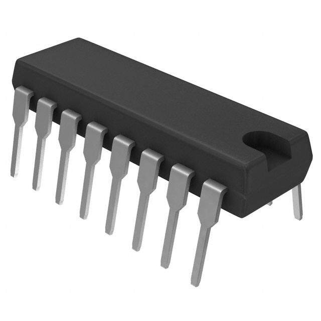
ICGOO在线商城 > 集成电路(IC) > 接口 - 模拟开关,多路复用器,多路分解器 > MAX4510EUT+T
- 型号: MAX4510EUT+T
- 制造商: Maxim
- 库位|库存: xxxx|xxxx
- 要求:
| 数量阶梯 | 香港交货 | 国内含税 |
| +xxxx | $xxxx | ¥xxxx |
查看当月历史价格
查看今年历史价格
MAX4510EUT+T产品简介:
ICGOO电子元器件商城为您提供MAX4510EUT+T由Maxim设计生产,在icgoo商城现货销售,并且可以通过原厂、代理商等渠道进行代购。 MAX4510EUT+T价格参考。MaximMAX4510EUT+T封装/规格:接口 - 模拟开关,多路复用器,多路分解器, 1 Circuit IC Switch 1:1 160 Ohm SOT-23-6。您可以下载MAX4510EUT+T参考资料、Datasheet数据手册功能说明书,资料中有MAX4510EUT+T 详细功能的应用电路图电压和使用方法及教程。
MAX4510EUT+T 是 Maxim Integrated 生产的一款模拟开关,属于接口类的模拟开关、多路复用器和多路分解器。该器件具有低导通电阻(RON)、快速切换时间和低功耗等特点,适用于多种应用场景。

 主要应用场景:

1. 音频信号切换:
   MAX4510EUT+T 可用于音频设备中的信号切换,例如在家庭影院系统中,它可以在多个音频源(如电视、蓝光播放器、游戏机等)之间进行切换,确保用户能够选择所需的音频输入。其低导通电阻特性可以减少信号失真,提供高质量的音频体验。

2. 传感器信号处理:
   在工业自动化和物联网(IoT)应用中,MAX4510EUT+T 可以用于多通道传感器信号的采集和处理。例如,在环境监测系统中,它可以将多个温度、湿度或压力传感器的信号路由到一个中央处理器,实现多路信号的高效管理。

3. 通信设备中的信号路由:
   该器件适用于通信设备中的信号路由,如在基站、路由器或其他网络设备中,MAX4510EUT+T 可以在不同的射频(RF)或基带信号之间进行切换,确保信号的可靠传输。其快速切换时间使得它能够在高速数据传输环境中保持性能稳定。

4. 医疗设备中的信号隔离与切换:
   在医疗设备中,MAX4510EUT+T 可用于心电图(ECG)、脑电图(EEG)等设备中的信号隔离与切换。它的低泄漏电流和高可靠性确保了生物电信号的准确性和安全性,同时减少了对患者的干扰。

5. 测试与测量仪器:
   在测试与测量仪器中,MAX4510EUT+T 可以用于多通道信号的自动切换,帮助工程师更高效地进行测试。例如,在示波器或多通道数据采集系统中,它可以快速切换不同的输入通道,提高测试效率。

6. 消费电子产品的功能扩展:
   在智能手机、平板电脑等消费电子产品中,MAX4510EUT+T 可以用于扩展设备的功能,如在不同外设(耳机、充电器、USB设备等)之间进行切换,提升用户体验。

总之,MAX4510EUT+T 凭借其优异的电气性能和可靠性,广泛应用于需要高效、低损耗信号切换的各种场景中。
| 参数 | 数值 |
| 产品目录 | 集成电路 (IC)半导体 |
| 描述 | IC ANALOG SWITCH SPST SOT23-6模拟开关 IC Fault-Protected SPST Analog Switch |
| 产品分类 | |
| 品牌 | Maxim Integrated |
| 产品手册 | |
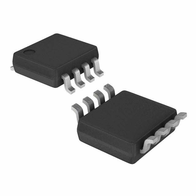
| 产品图片 |
|
| rohs | 符合RoHS无铅 / 符合限制有害物质指令(RoHS)规范要求 |
| 产品系列 | 开关 IC,模拟开关 IC,Maxim Integrated MAX4510EUT+T- |
| 数据手册 | |
| 产品型号 | MAX4510EUT+T |
| 产品培训模块 | http://www.digikey.cn/PTM/IndividualPTM.page?site=cn&lang=zhs&ptm=25703http://www.digikey.cn/PTM/IndividualPTM.page?site=cn&lang=zhs&ptm=25705 |
| 产品目录页面 | |
| 产品种类 | 模拟开关 IC |
| 供应商器件封装 | SOT-23-6 |
| 其它名称 | MAX4510EUT+TCT |
| 功能 | |
| 包装 | 剪切带 (CT) |
| 商标 | Maxim Integrated |
| 安装类型 | 表面贴装 |
| 安装风格 | SMD/SMT |
| 导通电阻 | 390 欧姆 |
| 导通电阻—最大值 | 390 Ohms |
| 封装 | Reel |
| 封装/外壳 | SOT-23-6 |
| 封装/箱体 | SOT-23-6 |
| 工作温度 | -40°C ~ 85°C |
| 工作电源电压 | +/- 4.5 V to +/- 20 V |
| 工厂包装数量 | 2500 |
| 应用说明 | |
| 开关数量 | 1 |
| 开关配置 | SPST |
| 最大功率耗散 | 696 mW |
| 最大双重电源电压 | +/- 20 V |
| 最大工作温度 | + 85 C |
| 最小工作温度 | - 40 C |
| 标准包装 | 1 |
| 电压-电源,单/双 (±) | 9 V ~ 36 V, ±4.5 V ~ 20 V |
| 电压源 | 单/双电源 |
| 电流-电源 | 50µA |
| 电源电压-最大 | 36 V |
| 电源电压-最小 | 9 V |
| 电源电流 | 250 uA |
| 电源电流—最大值 | 0.175 mA |
| 电路 | 1 x SPST - NC |
| 空闲时间—最大值 | 750 ns |
| 系列 | MAX4510 |
| 运行时间—最大值 | 200 ns |
| 零件号别名 | MAX4510 |


- 商务部:美国ITC正式对集成电路等产品启动337调查
- 曝三星4nm工艺存在良率问题 高通将骁龙8 Gen1或转产台积电
- 太阳诱电将投资9.5亿元在常州建新厂生产MLCC 预计2023年完工
- 英特尔发布欧洲新工厂建设计划 深化IDM 2.0 战略
- 台积电先进制程称霸业界 有大客户加持明年业绩稳了
- 达到5530亿美元!SIA预计今年全球半导体销售额将创下新高
- 英特尔拟将自动驾驶子公司Mobileye上市 估值或超500亿美元
- 三星加码芯片和SET,合并消费电子和移动部门,撤换高东真等 CEO
- 三星电子宣布重大人事变动 还合并消费电子和移动部门
- 海关总署:前11个月进口集成电路产品价值2.52万亿元 增长14.8%
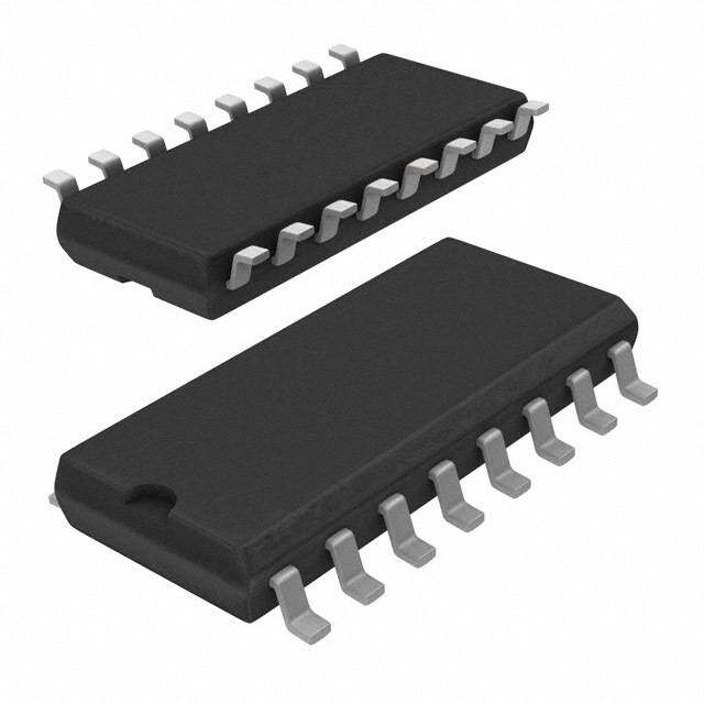
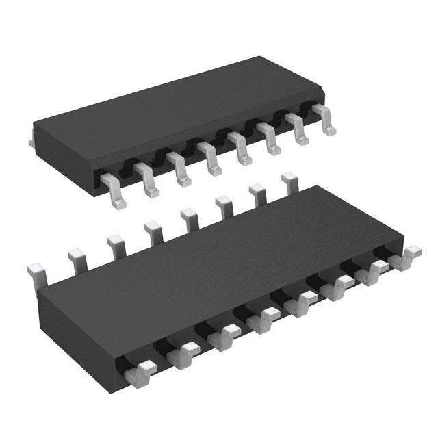


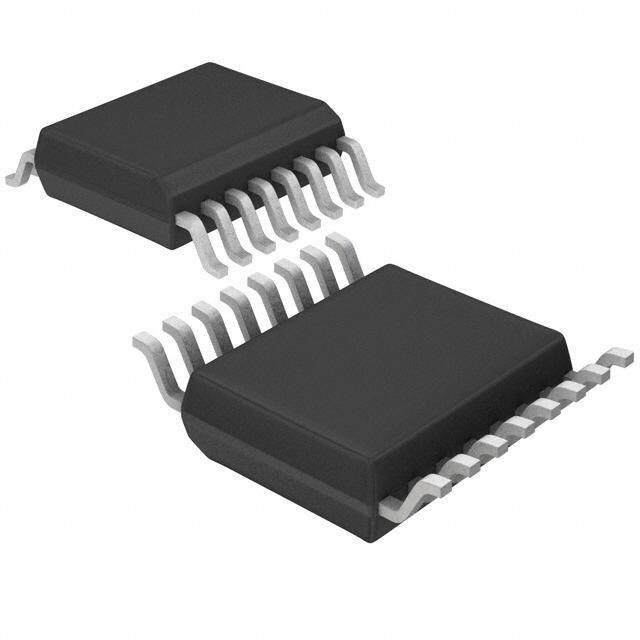

PDF Datasheet 数据手册内容提取
19-1542; Rev 0; 10/99 Rail-to-Rail, Fault-Protected, SPST Analog Switches General Description Features M The MAX4510/MAX4520 single-pole/single-throw (SPST), (cid:2) ±40V Fault Protection with Power Off A fault-protected analog switches feature a fault-protected ±36V Fault Protection with ±15V Supplies input and Rail-to-Rail® signal-handling capability. The X normally open (NO) and normally closed (NC) terminals (cid:2) Switch is Off with Power Removed 4 are protected from overvoltage faults up to 36V during (cid:2) Rail-to-Rail Signal Handling 5 power-on and 44V with power off. During a fault condi- tion, the switch input terminal (NO or NC) becomes an (cid:2) 160Ωmax Signal Paths with ±15V Supplies 1 0 open circuit; only nanoamperes of leakage current flow (cid:2) On-Switch Turns Off with Overvoltage from the fault source, and the switch output (COM) fur- /M nishes up to 13mA of the appropriate polarity supply (cid:2) 0.5nA Off-Leakage Current voltage to the load. This ensures unambiguous rail-to-rail (cid:2) Output Clamped to Appropriate Supply Voltage A outputs when a fault begins and ends. X During Fault Condition; No Transition Glitch On-resistance is 160Ω max. The off-leakage current is (cid:2) No Power-Supply Sequencing Required 4 only 0.5nA at +25°C and 10nA at +85°C. The MAX4510 5 is a normally closed switch, while the MAX4520 is a (cid:2) ±4.5V to ±20V Dual Supplies 2 normally open switch. These CMOS switches operate +9V to +36V Single Supply with dual power supplies ranging from ±4.5V to ±20V 0 or a single supply between +9V and +36V. (cid:2) Low Power Consumption: <2mW The digital input has +0.8V and +2.4V logic thresholds, (cid:2) TTL- and CMOS-Compatible Logic Inputs with ensuring both TTL- and CMOS-logic compatibility when Single +9V to +15V or ±15V Supplies using ±15V or a single +12V supply. The MAX4510/ MAX4520 are available in 6-pin SOT23 and 8-pin µMAX packages. Pin Configurations/Truth Tables Applications Data Acquisition TOP VIEW Industrial and Process-Control Systems Avionics V+ 1 6 NC (NO) ATE Equipment MAX4510 Redundant/Backup Systems V- 2 MAX4520 5 COM IN 3 4 GND SOT23 Ordering Information ( ) ARE FOR MAX4520. PIN- TOP PART TEMP. RANGE PACKAGE MARK IN MAX4510 MAX4520 MAX4510EUT-T -40°C to +85°C 6 SOT23-6 AABZ 0 ON OFF MAX4510EUA -40°C to +85°C 8 µMAX — 1 OFF ON MAX4520EUT-T -40°C to +85°C 6 SOT23-6 AADK MAX4520EUA -40°C to +85°C 8 µMAX — SWITCHES SHOWN FOR LOGIC "0" INPUT. ALL SWITCHES ARE OFF WITH POWER REMOVED. Rail-to-Rail is a registered trademark of Nippon Motorola, Ltd. Pin Configurations continued at end of data sheet. ________________________________________________________________Maxim Integrated Products 1 For free samples & the latest literature: http://www.maxim-ic.com, or phone 1-800-998-8800. For small orders, phone 1-800-835-8769.
Rail-to-Rail, Fault-Protected, SPST Analog Switches 0 ABSOLUTE MAXIMUM RATINGS 2 (Voltages Referenced to GND) Continuous Power Dissipation (TA= +70°C) (Note 2) 5 V+........................................................................-0.3V to +44.0V 6-Pin SOT23-6 (derate 7.1mW/°C above +70°C).........696mW V-.........................................................................-44.0V to +0.3V 8-Pin µMAX (derate 4.10mW/°C above +70°C)............330mW 4 V+ to V-................................................................-0.3V to +44.0V Operating Temperature Ranges X COM, IN (Note 1)..................................(V- - 0.3V) to (V+ + 0.3V) MAX45_0EUT....................................................-40°C to +85°C NC, NO (Note 2).....................................(V+ - 36V) to (V- + 36V) MAX45_0EUA...................................................-40°C to +85°C A NC, NO to COM.......................................................-36V to +36V Storage Temperature Range.............................-65°C to +150°C M Continuous Current into Any Terminal..............................±30mA Lead Temperature (soldering, 10sec).............................+300°C Peak Current into Any Terminal 0/ (pulsed at 1ms, 10% duty cycle)...................................±50mA 1 Note 1: COM and IN pins are not fault protected. Signals on COM or IN exceeding V+ or V- are clamped by internal diodes. Limit 5 forward diode current to maximum current rating. 4 Note 2: NC and NO pins are fault protected. Signals on NC or NO exceeding -36V to +36V may damage the device. These limits apply with power applied to V+ or V-, or ±40V with V+ = V- = 0. X A Stresses beyond those listed under “Absolute Maximum Ratings” may cause permanent damage to the device. These are stress ratings only, and functional M operation of the device at these or any other conditions beyond those indicated in the operational sections of the specifications is not implied. Exposure to absolute maximum rating conditions for extended periods may affect device reliability. ELECTRICAL CHARACTERISTICS—Dual Supplies (V+ = +15V, V- = -15V, GND = 0, VIH = 2.4V, VIL = 0.8V, TA = TMIN to TMAX, unless otherwise noted. Typical values are at TA = +25°C.) (Note 3) PARAMETER SYMBOL CONDITIONS TA MIN TYP MAX UNITS ANALOG SWITCH Fault-Free Analog Signal Range VNO, VNC Applies with power on or off E V- V+ V +25°C 125 160 On-Resistance RON VCOM= ±10V, ICOM= 1mA Ω E 225 N(NOo toers N 4C, 5O)ff-LeakageCurrent IINNOC((OOFFFF)), VVCNOOM,V=C O±M1 4=V +–; 14V +2E5°C --01.05 0.01 01.05 nA C(NOoMte sO 4ff,- L5e)akage Current ICOM(OFF) VVCNOOM,V=N C± 1=4 +–V1; 4V +2E5°C --01.05 0.01 01.05 nA C(NOoMte sO 4n,- L5e)akage Current ICOM(ON) V±C14OVM o=r ±un1c4oVn; nVeNcOte, dVNC= +2E5°C --02.05 0.01 02.05 nA FAULT(V+ = +15V, V- = -15V, unless otherwise noted.) Fault-Protected Analog Applies with power on (Note 6) -36 36 Signal Range VNO, VNC Applies with power off (Note 6) E -40 40 V COM Off-Leakage Current, +25°C -10 10 Supplies On ICOM(OFF) VNOor VNC= ±36V E -200 200 nA NCOur roern Nt, CS uInpppulite Ls eOankage INO, INC VVNCOOMor= V +–N1C0=V ±36V, +2E5°C --22000 22000 nA NCOur roern Nt, CS uInpppulite Ls eOafkfage INO, INC VVN+O =o 0r, VVN- C== 0 ±40V, +2E5°C --22000 0.1 22000 nA Clamp Output Current, VNOor VNC= 36V 8 11 13 Supplies On ICOM VNOor VNC= -36V +25°C -12 -10 -7 mA 2 _______________________________________________________________________________________
Rail-to-Rail, Fault-Protected, SPST Analog Switches ELECTRICAL CHARACTERISTICS—Dual Supplies (continued) M (V+ = +15V, V- = -15V, VIH = 2.4V, VIL = 0.8V, GND = 0, TA = TMIN to TMAX, unless otherwise noted. Typical values are at TA = A +25°C.) (Note 3) X PARAMETER SYMBOL CONDITIONS TA MIN TYP MAX UNITS Clamp Output Resistance, +25°C 1 2.5 4 Supplies On RCOM VNOor VNC= ±36V E 3 kΩ 5 Fault Trip Threshold +25°C V-- 0.4 V+ + 0.4 V 1 0 Fault Output Turn-On Delay Time VIN= ±25V, RL= 10kΩ +25°C 10 ns /M Fault Recovery Time VIN= ±25V, RL= 10kΩ +25°C 2.5 µs A LOGIC INPUT X IN Input Logic High VINH E 2.4 V IN Input Logic Low VINL E 0.8 V 4 +25°C -1 0.03 1 5 IN Input Current IINH, IINL VIN= 0.8V or 2.4V E -5 5 µA 2 SWITCH DYNAMIC CHARACTERISTICS 0 Turn-On Time tON VCNLO= o3r5 VpNFC, F=ig ±u1re0 V2, RL= 2kΩ, +2E5°C 350 650000 ns Turn-Off Time tOFF VCNLO= o3r5 VpNFC, F=ig ±u1re0 V2, RL= 2kΩ, +2E5°C 60 215705 ns Charge Injection (Note 7) Q CL= 1nF, VNO= 0, +25°C 1.5 5 pC RS = 0Ω, Figure 3 NO or NC Off-Capacitance CN(OFF) f = 1MHz, Figure 4 +25°C 10 pF COM Off-Capacitance CCOM(OFF) f = 1MHz, Figure 4 +25°C 5 pF COM On-Capacitance CCOM(ON) f = 1MHz, Figure 4 +25°C 10 pF Off-Isolation (Note 8) VCISO RVNL_== 5 10VΩR,M CSL, f= = 1 15MpHF,z, Figure 5 +25°C -62 dB POWER SUPPLY Power-Supply Range V+, V- E ±4.5 ±20 V +25°C 100 175 V+ Supply Current I+ VIN= 0 or 5V µA E 250 +25°C 50 100 V- Supply Current I- VIN= 0 or 5V µA E 175 +25°C -1 0.01 1 VIN= 0 or 15V E 10 GND Supply Current IGND µA +25°C 50 100 VIN= 5V E 175 _______________________________________________________________________________________ 3
Rail-to-Rail, Fault-Protected, SPST Analog Switches 0 ELECTRICAL CHARACTERISTICS—Single +12V Supply 2 (V+ = +12V, V- = 0, GND = 0, VIH= 2.4V, VIL= 0.8V, TA= TMINto TMAX, unless otherwise noted. Typical values are at TA= +25°C.) 5 (Note 3) 4 PARAMETER SYMBOL CONDITIONS TA MIN TYP MAX UNITS X ANALOG SWITCH A Fault-Free Analog Signal Range VNO, VNC Applies with power on or off E 0 V+ V M On-Resistance RON IVCCOOMM== 1 1m0AV, +2E5°C 260 530900 Ω / 0 NO or NC Off-Leakage Current INO(OFF), VCOM= 10V, 1V; +25°C -0.5 0.01 0.5 nA 1 (Notes 4, 5, 9) INC(OFF) VNO, VNC = 1V, 10V E -10 10 45 C(NOoMte sO 4ff,- L5e, a9k)age Current ICOM(OFF) VVCNOOM, V N=C 1 =V ,1 100VV, ;1V +2E5°C --01.05 0.01 01.05 nA AX C(NOoMte sO 4n,- L5e, a9k)age Current ICOM(ON) 1VVC,O 1M0 V=, o1rV u, n1c0oVn; nVeNcOte, dVNC = +2E5°C --02.05 0.01 02.05 nA M FAULT Fault-Protected Analog Applies with power on (Note 6) -36 36 Signal Range VNO, VNC Applies with power off (Note 6) E -40 40 V COM Off-Leakage Current, +25°C -10 10 Supply On ICOM VNOor VNC= ±36V E -200 200 nA NCOur roern Nt, CS uInpppulyt LOenakage INO, INC VVNCOOMor= V 0NC= ±36V, +2E5°C --22000 22000 nA NCOur roern Nt, CS uInpppulyt LOeffakage INO, INC VVN+O =o 0r, VVN- C== 0 ±40V, +2E5°C --22000 0.1 22000 nA Clamp Output Current, Supply On ICOM VNOor VNC= 36V +25°C 2 3 5 mA Clamp Output Resistance, Supply On RCOM VNOor VNC= 36V +25°C 2.4 5 kΩ LOGIC INPUT IN Input Logic High VINH E 2.4 V IN Input Logic Low VINL E 0.8 V +25°C -1 0.03 1 IN Input Current IINH, IINL VIN= 0.8V or 2.4V µA E -5 5 4 _______________________________________________________________________________________
Rail-to-Rail, Fault-Protected, SPST Analog Switches ELECTRICAL CHARACTERISTICS—Single +12V Supply (continued) M (V+ = +12V, V- = 0, GND = 0, VIH= 2.4V, VIL= 0.8V, TA= TMINto TMAX, unless otherwise noted. Typical values are at TA= +25°C.) A (Note 3) X PARAMETER SYMBOL CONDITIONS TA MIN TYP MAX UNITS 4 SWITCH DYNAMICCHARACTERISTICS Turn-On Time tON VCNLO= o 3r5 VpNFC, F=ig 7uVre, R2L= 2kΩ, +2E5°C 500 1705000 ns 51 0 Turn-Off Time tOFF VCNLO= o 3r5 VpNFC, F=ig 7uVre, R2L= 2kΩ, +2E5°C 60 320000 ns /M Charge Injection (Note 7) Q CL= 1nF, VNO= 0, +25°C 1 5 pC A RS= 0Ω, Figure 3 X NO or NC Off-Capacitance CCNNOC((OOFFFF)), f = 1MHz, Figure 4 +25°C 9 pF 4 5 COM Off-Capacitance CCOM(OFF) VCOM= 0, f = 1MHz, Figure 4 +25°C 9 pF 2 COM On-Capacitance CCOM(ON) Vf =C O1MMH= zV, NFOig=ur 0e, 4 +25°C 22 pF 0 Off-Isolation (Note 8) VISO RVILN== 510VΩR,M CS,L f == 115MpHFz,, Figure 5 +25°C -62 dB POWER SUPPLY Power-Supply Range V+ E 9 36 V +25°C 50 125 V+ Supply Current I+ VIN= 0 or 5V µA E 175 +25°C 25 75 VIN= 0 or 12V µA E 125 V- and GND Supply Current IGND +25°C 50 125 VIN= 0 or 5V µA E 175 Note 3: Algebraic convention is used in this data sheet; the most negative value is shown in the minimum column. Note 4: Leakage parameters are 100% tested at maximum-rated hot temperature and guaranteed by correlation at TA= +25°C. Note 5: SOT packages are 100% tested at +25°C. Limits at the maximum-rated temperature are guaranteed by design and corre- lation limits at +25°C. Leakage tests for the SOTpackage are typical only. Note 6: NC and NO pins are fault protected. Signals on NC or NO exceeding -36V to +36V may damage the device. These limits apply with power applied to V+ or V-, or ±40V with V+ = V- = 0. Note 7: Guaranteed by design. Note 8: Off isolation = 20log10[ VCOM/ (VNCor VNO) ], VCOM= output, VNCor VNO= input to off switch. Note 9: Leakage testing for single-supply operation is guaranteed by testing with dual supplies. _______________________________________________________________________________________ 5
Rail-to-Rail, Fault-Protected, SPST Analog Switches 0 __________________________________________Typical Operating Characteristics 2 (TA = +25°C, unless otherwise noted.) 5 4 SWITCH ON-RESISTANCE SWITCH ON-RESISTANCE vs. VCOM AND SWITCH ON-RESISTANCE X vs. VCOM (DUAL SUPPLIES) TEMPERATURE (DUAL SUPPLIES) vs. VCOM (SINGLE SUPPLY) X4510/MA ΩWITCH ON-RESISTANCE () 122133050505000000 VVVV+-+- == == +- +-115500VVVV VV+- == +-1122VV MAX4510-01 ΩWITCH ON-RESISTANCE () 1111128664028000000000 TA = -55T°AC = +1T2A5 =° C-40°TCA = +85°TCA = +25°C MAX4510-02 ΩWITCH ON-RESISTANCE ()101000 VV++ == ++254VVV+ =V +V+ +1= 2 =+V 3+0V1V+5 V= V++2 0=V +36V MAX4510-03 S V+ = +15V S 40 S A 50 V- = -15V VV+- == +-2200VV 20 VV+- == +-1155VV M 0 0 1 -20 -15 -10 -5 0 5 10 15 20 -15 -10 -5 0 5 10 15 0 5 10 15 20 25 30 35 40 VCOM (V) VCOM (V) VCOM (V) SWITCH ON-RESISTANCE vs. VCOM ID(ON), IS(OFF), AND ID(OFF) CHARGE INJECTION AND TEMPERATURE (SINGLE SUPPLY) LEAKAGES vs. TEMPERATURE vs. VCOM (DUAL SUPPLIES) Ω)345000 TA = +125°C TA = +85°C MAX4510-04 11000nn IVCCOOMM(O =F F+)1 A4TV VNO = -14V, MAX4510-05 1124 VV+- == -+1155VV MAX4510-06 E (300 ICOM(OFF) AT VNO = +14V, 10 H ON-RESISTANC212055000 TA = +25°C TA = -40°C LEAKAGE (A)1010np VI=CC VOOMCMO( OM=N -)= 1 A-4T1V 4VVNO I=C VOMCO(OMN )= A+T1 4VVNO Q (pC) 86 DSUUAPLP L±I1E5SV C WIT100 TA = -55°C INO(OFF) AT VNO = -14V, 4 SINGLE +12V S 10p VCOM = +14V SUPPLY 50 INO(OFF) AT VNO = +14V, 2 V+ = +12V VCOM = -14V 0 1p 0 0 2 4 6 8 10 12 -50 -25 0 25 50 75 100 125 150 -15 -10 -5 0 5 10 15 VCOM (V) TEMPERATURE (°C) VCOM (V) ON- AND OFF-TIMES ON- AND OFF-TIMES POWER-SUPPLY CURRENT vs. vs. SUPPLY VOLTAGE vs. TEMPERATURE TEMPERATURE t, t (ns)ONOFF1786549000000000000000 (DUAL StOUNPPLIES) (SINGLEtO SNUPPLY) MAX4510-07 t, t (ns)ONOFF354600000000 tON MAX4510-08 PLY CURRENT (µA) 112550000000 IGIN+D VVV+-IN = == - ++11555VVV MAX4510/20 toc 09 300 tOFF 200 SUP -50 210000 tOFF (SSUINPGPLLYE) 100 tOFF -100 I- (DUAL SUPPLIES) 0 0 -150 0 5 10 15 20 -50 -25 0 25 50 75 100 125 -40 -20 0 20 40 60 80 100 SUPPLY VOLTAGE (±V) TEMPERATURE (°C) TEMPERATURE (°C) 6 _______________________________________________________________________________________
Rail-to-Rail, Fault-Protected, SPST Analog Switches Typical Operating Characteristics (continued) M (TA= +25°C, unless otherwise noted.) A X 4 LOGIC-LEVEL THRESHOLD vs. V+ FREQUENCY RESPONSE LD (V) 23..50 MAX4511-10 ---3210000 ON LOSS MAX4510/20 TOC11 510/ O 2.0 M H -40 EL THRES 1.5 OSS (dB) --6500 OFF LOSS A LEV L -70 X C- 1.0 GI -80 4 O L 0.5 -90 5 V+ = +15V -100 V- = -15V 2 0 -110 0 0 5 10 15 20 25 30 35 0.01 0.1 1 10 100 1000 V+ (V) FREQUENCY (MHz) Pin Description Detailed Description PIN Overview of Traditional NAME FUNCTION SOT23-6 µMAX Fault-Protected Switches Positive Supply Voltage The MAX4510/MAX4520 are fault-protected CMOS 1 8 V+ Input analog switches with unusual operation and construc- tion. Traditional fault-protected switches are construct- Negative Supply Voltage ed by three series FETs. This produces good off 2 5 V- Input. Connect to GND for characteristics, but fairly high on-resistance when the single-supply operation. signals are within about 3V of each supply rail. As the 3 6 IN Logic Control Digital Input voltage on one side of the switch approaches within about 3V of either supply rail (a fault condition), the 4 4 GND Ground switch impedance becomes higher, limiting the output Analog Switch Common signal range (on the protected side of the switch) to 5 1 COM Terminal approximately 3V less than the appropriate polarity supply voltage. Fault-Protected Analog During a fault condition, the output current that flows Switch—normally closed from the protected side of the switch into its load comes 6 3 NC or NO (NC) for MAX4510; from the fault source on the other side of the switch. If normally open (NO) for MAX4520 the switch is open or the load is extremely high imped- ance, the input current will be very low. If the switch is No Connection. Not inter- on and the load is low impedance, enough current will — 2, 7 N.C. nally connected. flow from the source to maintain the load voltage at 3V less than the supply. _______________________________________________________________________________________ 7
Rail-to-Rail, Fault-Protected, SPST Analog Switches 0 2 NORMALLY OPEN SWITCH CONSTRUCTION 5 V+ P2 4 X HIGH A FAULT M P1 / 0 NO COM 1 (NC) N1 LOW 5 FAULT 4 X ON IN A M GND N2 V- -ESD DIODE NC SWITCH MAX4510 MAX4520 Figure 1. Functional Diagram Overview of MAX4510/MAX4520 When power is removed, the fault protection is still in The MAX4510/MAX4520 differ considerably from tradi- effect. In this case, the NO or NC terminals are a virtual tional fault-protection switches, with several advan- open circuit. The fault can be up to ±40V. tages. First, they are constructed with two parallel The COM pin is not fault protected; it acts as a normal FETs, allowing very low on-resistance when the switch CMOS switch pin. If a voltage source is connected to is on. Second, they allow signals on the NC or NO pins the COM pin, it should be limited to the supply volt- that are within or slightly beyond the supply rails to be ages. Exceeding the supply voltage will cause high passed through the switch to the COM terminal, allow- currents to flow through the ESD protection diodes, ing rail-to-rail signal operation. Third, when a signal on possibly damaging the device (see Absolute Maximum NC or NO exceeds the supply rails by about 50mV (a Ratings). fault condition), the voltage on COM is limited to the appropriate polarity supply voltage. Operation is identi- Internal Construction cal for both fault polarities. The fault-protection extends Internal construction is shown in Figure 1, with the ana- to ±36V from GND. log signal paths shown in bold. A single normally open (NO) switch is shown; the normally closed (NC) config- During a fault condition, the NO or NC input pin uration is identical except the logic-level translator becomes high impedance regardless of the switch becomes an inverter. The analog switch is formed by state or load resistance. If the switch is on, the COM the parallel combination of N-channel FET N1 and P- output current is furnished from the V+ or V- pin by channel FET P1, which are driven on and off simultane- “booster” FETs connected to each supply pin. These ously according to the input fault condition and the FETs can typically source or sink up to 13mA. logic-level state. 8 _______________________________________________________________________________________
Rail-to-Rail, Fault-Protected, SPST Analog Switches Normal Operation than 300mV, one of these diodes will conduct heavily. M Two comparators continuously compare the voltage on During normal operation these reverse-biased ESD the NO (or NC) pin with V+ and V-. When the signal on diodes leak a few nanoamps of current to V+ and V-. A NO or NC is between V+ and V-, the switch acts nor- X Fault-Protection Voltage and Power Off mally, with FETs N1 and P1 turning on and off in The maximum fault voltage on the NC or NO pins is 4 response to IN signals. The parallel combination of N1 and P1 forms a low-value resistor between NO (or NC) ±36V with power applied and ±40V with power off. 5 and COM so that signals pass equally well in either 1 Failure Modes direction. 0 The MAX4510/MAX4520 are not lightning arrestors or Positive Fault Condition surge protectors. /M When the signal on NO (or NC) exceeds V+ by about Exceeding the fault-protection voltage limits on NO or A 50mV, the high-fault comparator output is high, turning NC, even for very short periods, can cause the device off FETs N1 and P1. This makes the NO (or NC) pin to fail. X high impedance regardless of the switch state. If the Ground 4 switch state is “off,” all FETs are turned off and both NO There is no connection between the analog signal path 5 (or NC) and COM are high impedance. If the switch state is “on,” FET P2 is turned on, sourcing current from and GND. The analog signal path consists of an N- 2 V+ to COM. channel and P-channel MOSFET with their sources and 0 drains paralleled and their gates driven out of phase to Negative Fault Condition V+ and V- by the logic-level translators. When the signal on NO (or NC) exceeds V- by about V+ and GND power the internal logic and logic-level 50mV, the low-fault comparator output is high, turning translators and set the input logic thresholds. The logic- off FETs N1 and P1. This makes the NO (or NC) pin level translators convert the logic levels to switched V+ high impedance regardless of the switch state. If the and V- signals to drive the gates of the analog switch. switch state is “off,” all FETs are turned off and both NO This drive signal is the only connection between the (or NC) and COM are high impedance. If the switch power supplies and the analog signal. GND, IN, and state is “on,” FET N2 is turned on, sinking current from COM have ESD-protection diodes to V+ and V-. COM to V-. IN Logic-Level Thresholds Transient Fault Response and Recovery The logic-level thresholds are CMOS and TTL compati- When a fast rise-time and fall-time transient on IN ble when V+ is +15V. As V+ is raised, the threshold exceeds V+ or V-, the output (COM) follows the input (IN) increases slightly, and when V+ reaches 25V, the level to the supply rail with only a few nanoseconds delay. threshold is about 2.8V—above the TTL output high- This delay is due to the switch on-resistance and circuit level minimum of 2.4V, but still compatible with CMOS capacitance to ground. When the input transient returns outputs (see Typical Operating Characteristics). to within the supply rails, however, there is a longer out- Increasing V- has no effect on the logic-level thresholds, put recovery time delay. For positive faults, the recovery but it does increase the gate-drive voltage to the signal time is typically 3.5µs. For negative faults, the recovery FETs, reducing their on-resistance. time is typically 1.3µs. These values depend on the COM output resistance and capacitance. The delays are not Dual Supplies dependent on the fault amplitude. Higher COM output The MAX4510/MAX4520 operate with dual supplies resistance and capacitance increase recovery times. between ±4.5V and ±20V. The V+ and V- supplies COM and IN Pins need not be symmetrical, but their difference cannot exceed the absolute maximum rating of 44V. FETs N2 and P2 can source about ±13mA from V+ or V- to the COM pin in the fault condition. Ensure that if the Single Supply COM pin is connected to a low-resistance load, the The MAX4510/MAX4520 operate from a single supply absolute maximum current rating of 30mA is never between +9V and +36V when V- is connected to GND. exceeded, both in normal and fault conditions. The GND, COM, and IN pins do not have fault protec- tion. Reverse ESD-protection diodes are internally con- nected between GND, COM, IN, and both V+ and V-. If a signal on GND, COM, or IN exceeds V+ or V- by more _______________________________________________________________________________________ 9
Rail-to-Rail, Fault-Protected, SPST Analog Switches 0 Test Circuits/Timing Diagrams 2 5 V+ 4 tr < 20ns X V+ LOGIC +3V tf < 20ns A NO OR NC VNO OR INPUT 0V 50% VNC M MAX4510 MAX4520 tOFF / VIN 0 IN COM VOUT 51 50Ω GND V- 2k 35pF SWITCH 0V VOUT 0.9 · V0UT 0.9 · VOUT OUTPUT 4 tON X V- LOGIC INPUT WAVEFORMS INVERTED FOR SWITCHES A THAT HAVE THE OPPOSITE LOGIC SENSE. M V- IS CONNECTED TO GND FOR SINGLE-SUPPLY OPERATION. Figure 2. Switch Turn-On/Turn-Off Times V+ VIN V+ V+ IN NO OR NC VIN 0V 50Ω MAX4510 MAX4520 COM VOUT VOUT ∆ VOUT GND V- CL 1000pF V- ∆ VOUT IS THE MEASURED VOLTAGE DUE TO CHARGE- TRANSFER ERROR Q WHEN THE CHANNEL TURNS OFF. V- IS CONNECTED TO GND FOR SINGLE-SUPPLY OPERATION. Q = ∆ VOUT · CL Figure 3. Charge Injection 10 ______________________________________________________________________________________
Rail-to-Rail, Fault-Protected, SPST Analog Switches Test Circuits/Timing Diagrams (continued) M A X V+ 4 5 V+ 1 NO OR NC 0 / MAX4510 M MAX4520 COM 1MHz VIN IN CAPACITANCE A ANALYZER GND V- X 4 5 V- 2 V- IS CONNECTED TO GND FOR SINGLE-SUPPLY OPERATION. 0 Figure 4. COM, NO, and NC Capacitance V+ 10nF NETWORK ANALYZER V+ VIN 50Ω 50Ω COM OFF-ISOLATION = 20log VOUT MAX4510 VIN MAX4520 ON-LOSS = 20log VOUT VIN IN NO, NC VOUT MEAS REF VIN GND V- 50Ω 50Ω 10nF V- MEASUREMENTS ARE STANDARDIZED AGAINST SHORT AT SOCKET TERMINALS. OFF ISOLATION IS MEASURED BETWEEN COM AND “OFF” NO OR NC TERMINALS. ON LOSS IS MEASURED BETWEEN COM AND “ON” NO OR NC TERMINALS. V- IS CONNECTED TO GND FOR SINGLE-SUPPLY OPERATION. Figure 5. Frequency Response and Off-Isolation Chip Information TRANSISTOR COUNT: 139 ______________________________________________________________________________________ 11
Rail-to-Rail, Fault-Protected, SPST Analog Switches 0 Pin Configurations/Functional Diagrams/Truth Tables (continued) 2 5 4 COM 1 8 V+ COM 1 8 V+ X A N.C. 2 7 N.C. N.C. 2 7 N.C. M 0/ NC 3 6 IN NO 3 6 IN 1 5 GND 4 MAX4510 5 V- GND 4 MAX4520 5 V- 4 X µMAX µMAX A IN MAX4510 MAX4520 M N.C. = NOT CONNECTED 0 ON OFF SWITCHES SHOWN FOR LOGIC "0" INPUT. 1 OFF ON ALL SWITCHES ARE OFF WITH POWER REMOVED. ________________________________________________________Package Information OT.EPS 6LS Maxim cannot assume responsibility for use of any circuitry other than circuitry entirely embodied in a Maxim product. No circuit patent licenses are implied. Maxim reserves the right to change the circuitry and specifications without notice at any time. 12 ____________________Maxim Integrated Products, 120 San Gabriel Drive, Sunnyvale, CA 94086 408-737-7600 © 1999 Maxim Integrated Products Printed USA is a registered trademark of Maxim Integrated Products.
Mouser Electronics Authorized Distributor Click to View Pricing, Inventory, Delivery & Lifecycle Information: M axim Integrated: MAX4510EUT+T MAX4520EUA+ MAX4520EUA+T MAX4520EUT+T

 Datasheet下载


