ICGOO在线商城 > 开发板,套件,编程器 > 评估和演示板和套件 > MAX1978EVKIT
 Datasheet下载
- 型号: MAX1978EVKIT
- 制造商: Maxim
- 库位|库存: xxxx|xxxx
- 要求:
| 数量阶梯 | 香港交货 | 国内含税 |
| +xxxx | $xxxx | ¥xxxx |
查看当月历史价格
查看今年历史价格
MAX1978EVKIT产品简介:
ICGOO电子元器件商城为您提供MAX1978EVKIT由Maxim设计生产,在icgoo商城现货销售,并且可以通过原厂、代理商等渠道进行代购。 MAX1978EVKIT价格参考。MaximMAX1978EVKIT封装/规格:评估和演示板和套件, MAX1978 Thermal Management Power Management Evaluation Board。您可以下载MAX1978EVKIT参考资料、Datasheet数据手册功能说明书,资料中有MAX1978EVKIT 详细功能的应用电路图电压和使用方法及教程。
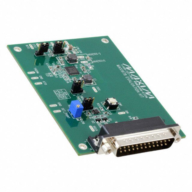
MAX1978EVKIT 是 Maxim Integrated 提供的一款评估板,用于评估 MAX1978 芯片的性能和功能。MAX1978 是一款高效、低噪声的降压型 DC-DC 转换器,专为需要高精度电压调节的应用场景设计。以下是 MAX1978EVKIT 的主要应用场景:

 1. 便携式电子设备
   - MAX1978EVKIT 可用于评估 MAX1978 在便携式电子设备中的表现,例如笔记本电脑、平板电脑和智能手机等。
   - 它能够提供稳定的电源输出,支持这些设备中的处理器、存储器和其他低功耗组件。

 2. 通信设备
   - 在无线通信基站、路由器和调制解调器中,MAX1978EVKIT 可帮助工程师评估其在供电系统中的性能。
   - 其高效的电源转换能力和低噪声特性非常适合为射频(RF)电路和数字信号处理器(DSP)供电。

 3. 工业自动化
   - 工业控制系统中需要高精度和低噪声的电源供应,MAX1978EVKIT 可用于评估其在可编程逻辑控制器(PLC)、数据采集系统(DAQ)和传感器接口中的应用。
   - 其宽输入电压范围(4.5V 至 18V)和可调输出电压(0.8V 至 5.5V)使其非常适合工业环境。

 4. 医疗设备
   - 在医疗仪器中,如监护仪、超声设备和便携式诊断工具,MAX1978EVKIT 可用于评估其为敏感电路(如放大器和模数转换器)供电的能力。
   - 其低纹波和高精度输出电压特性有助于提高设备的测量精度。

 5. 汽车电子
   - MAX1978EVKIT 可用于评估其在汽车电子系统中的应用,例如信息娱乐系统、导航设备和车载传感器。
   - 其宽输入电压范围和抗噪声能力使其能够在汽车环境中稳定工作。

 6. 测试与测量设备
   - 在示波器、信号发生器和功率计等测试设备中,MAX1978EVKIT 可用于评估其为关键组件供电的能力。
   - 其低噪声特性和快速瞬态响应确保了测试结果的准确性。

 总结
MAX1978EVKIT 主要应用于需要高效、低噪声和高精度电源转换的领域。通过使用该评估板,工程师可以轻松验证 MAX1978 的性能,并加速产品开发过程。
| 参数 | 数值 |
| 产品目录 | 编程器,开发系统嵌入式解决方案 |
| 描述 | EVAL KIT MAX1978交换机 IC 开发工具 MAX1978 EVAL KIT |
| 产品分类 | |
| 品牌 | Maxim Integrated |
| 产品手册 | |
| 产品图片 |
|
| rohs | 否含铅 / 不符合限制有害物质指令(RoHS)规范要求 |
| 产品系列 | 模拟与数字IC开发工具,交换机 IC 开发工具,Maxim Integrated MAX1978EVKIT- |
| 数据手册 | |
| 产品型号 | MAX1978EVKIT |
| 主要属性 | - |
| 主要用途 | 电源管理,热管理 |
| 产品 | Evaluation Kits |
| 产品种类 | 交换机 IC 开发工具 |
| 使用的IC/零件 | MAX1978 |
| 商标 | Maxim Integrated |
| 封装 | Bulk |
| 嵌入式 | - |
| 工具用于评估 | MAX1978 |
| 所含物品 | 板,软件 |
| 标准包装 | 1 |
| 类型 | Power Switches |
| 系列 | MAX1978 |
| 辅助属性 | - |
| 零件号别名 | MAX1978 |


- 商务部:美国ITC正式对集成电路等产品启动337调查
- 曝三星4nm工艺存在良率问题 高通将骁龙8 Gen1或转产台积电
- 太阳诱电将投资9.5亿元在常州建新厂生产MLCC 预计2023年完工
- 英特尔发布欧洲新工厂建设计划 深化IDM 2.0 战略
- 台积电先进制程称霸业界 有大客户加持明年业绩稳了
- 达到5530亿美元!SIA预计今年全球半导体销售额将创下新高
- 英特尔拟将自动驾驶子公司Mobileye上市 估值或超500亿美元
- 三星加码芯片和SET,合并消费电子和移动部门,撤换高东真等 CEO
- 三星电子宣布重大人事变动 还合并消费电子和移动部门
- 海关总署:前11个月进口集成电路产品价值2.52万亿元 增长14.8%

PDF Datasheet 数据手册内容提取
19-2612; Rev 0A; 12/02 MAX1978 Evaluation Kit General Description Features E The MAX1978 evaluation kit (EV kit) is a fully assembled (cid:2) Circuit Footprint Less than 0.93in2 v and tested PC board that implements a complete (cid:2) Circuit Height Less than 3mm a switch-mode temperature control system for a Peltier l thermo-electric cooler (TEC) module. It operates from a (cid:2) Operates from a Single Supply (3V to 5.5V) u single 3V to 5.5V supply and provides a bipolar ±2.2A (cid:2) ±2.2A Output Current a (max) output to the module. (cid:2) High-Efficiency Switch-Mode Design t e A potentiometer, DAC, or external source generates a (cid:2) Programmable Heating/Cooling Current Limit DC temperature set-point voltage. Thermal feedback s from the TEC module is compared to the set-point (cid:2) TEC Current Monitor Output : voltage to generate the TEC current control signal. The (cid:2) Overtemperature, Undertemperature, and Analog M MAX1978 controls TEC current to accurately regulate Temperature Monitor temperature. (cid:2) 500kHz or 1MHz Switching Frequency A When using the DAC, the EV kit connects to the parallel (cid:2) SPI™-Compatible Serial Interface X port of a computer running Windows®95, 98, or 2000. 1 (cid:2) Easy-to-Use Menu-Driven Software 9 (cid:2) Includes Windows 95-/98-/2000-Compatible 7 Software and Demo PC Board 8 (cid:2) Surface-Mount Construction (cid:2) Fully Assembled and Tested Ordering Information PART TEMP RANGE IC PACKAGE SPI is a trademark of Motorola, Inc. MAX1978EVKIT 0°C to +70°C 48 Thin QFN (7mm ✕ 7mm) Windows is a registered trademark of Microsoft Corp. Component List DESIGNATION QTY DESCRIPTION DESIGNATION QTY DESCRIPTION 4.7µF, 6.3V X5R, ceramic capacitor C5 0 Not installed (0402) (0805) 0.47µF, 6.3V X7R ceramic capacitor C1 1 Murata GRM21BR60J475M (0603) Taiyo Yuden JMK212BJ475MG C8 1 Murata GRM188R60J474K TDK C2012X5R0J475M Taiyo Yuden LMK107BJ474KA 1µF, 6.3V X5R ceramic capacitors TDK C1608X5R1A474K C2, CC71,7 C12, 4 (M0u6r0a3ta) GRM188R60J105M 0(0.044072µ)F, 10V X7R ceramic capacitor Taiyo Yuden JMK107BJ105MA C10 1 Murata GRP155R71A473K TDK C1608X5R1A105K Taiyo Yuden LMK105BJ473KV 10µF, 6.3V X5R ceramic capacitors TDK C1005X7R1C473K C3, C6, C9, 4 (M0u8r0a5ta) GRM21BR60J106K C16, C21 0 Not installed (0603) C11 22µF, 6.3V X5R ceramic capacitor Taiyo Yuden JMK212BJ106MG (1210) TDK C2012X5R0J106M C19 1 Murata GRM32DR60J226K 0.01µF, 16V X7R ceramic capacitor Taiyo Yuden JMK325BJ226MM (0402) TDK C3225X5R0J226M C4 1 Murata GRP155R71C103K Taiyo Yuden EMK105BJ103KV Component List continued on next page. TDK C1005X7R1E103K ________________________________________________________________Maxim Integrated Products 1 For pricing, delivery, and ordering information,please contact Maxim/Dallas Direct!at 1-888-629-4642, or visit Maxim’s website at www.maxim-ic.com.
MAX1978 Evaluation Kit 8 Component List (continued) 7 DESIGNATION QTY DESCRIPTION DESIGNATION QTY DESCRIPTION 9 1 C20 0 Not installed (1210) SW1 1 Switch, momentary, normally open X JU1, JU3, JU4 3 3-pin headers U1 1 MAX1978ETM 48-pin thin QFN-EP* JU2 1 2-pin header None 4 Shunts A M L1, L2 2 3µH, 2.4A inductors DAC AND INTERFACE COMPONENTS. REQUIRED ONLY Sumida CDRH5D28-3R0NC FOR EVALUATION. 0.068Ω ±1%, 0.5W sense resistor 0.1µF, 16V X7R ceramic capacitors : R1 1 (1206) (0603) s IRC LRC-LR1206-01-R068-F C13, C14, C15 3 Murata GRM188R71C104K e R2 1 49.9kΩ ±1% resistor (0402) Taiyo Yuden EMK107BJ104KA at R3 1 100kΩ ±1% resistor (0402) TDK C1608X7R1C104K C18 0 Not installed (0603) u R4–R8 0 Not installed (0402) J1 1 DB25 male right-angle connector l R9 1 80.6kΩ ±1% resistor (0603) a NPN bipolar transistors, SOT23 R10 1 69.8kΩ ±1% resistor (0603) v Central Semiconductor CMPT3904 E R11 1 105kΩ ±1% resistor (0603) Q1, Q2, Q3 3 Diodes Inc. MMBT3904 R12 1 20kΩ ±1% resistor (0603) Fairchild MMBT3904 R13 1 0 10.1k%Ω rteesmispto cro (e0f8fi0c5ie)nt = 25ppm/°C, R17, R18, R19, 4 G 1keΩn e±r5a%l S reemsiisctoonrsd u(0c6to0r3 M) MBT3904 R14 1 1MΩ ±5% resistor (0402) R23 R15 1 20kΩ ±5% resistor (0402) R20, R21, R22 3 4.7kΩ ±5% resistors (0603) R16 1 100kΩ ±5% resistor (0402) R24 1 20kΩ potentiometer (multiturn) R25, R26 2 100kΩ ±5% resistors (0603) U2 1 MAX5144EUB 10-pin µMAX *EP = Exposed pad. Component Suppliers SUPPLIER PHONE FAX WEBSITE Central Semiconductor 631-435-1110 631-435-1824 www.centralsemi.com Diodes Inc. 805-446-4800 805-381-3899 www.diodes.com Fairchild 888-522-5372 — www.fairchildsemi.com General Semiconductor 760-804-9258 760-804-9259 www.gensemi.com International Rectifier Co. (IRC) 361-992-7900 361-992-3377 www.irctt.com Murata 770-436-1300 770-436-3030 www.murata.com Sumida 847-545-6700 847-545-6720 www.sumida.com Taiyo Yuden 800-348-2496 847-925-0899 www.t-yuden.com TDK 847-803-6100 847-390-4405 www.component.tdk.com Note:Please indicate you are using the MAX1978 when contacting these manufacturers. Quick Start • One Peltier TEC module with a thermistor (NTC 10kΩ at +25°C) Required Equipment • One digital voltmeter (DVM) The following equipment is required before beginning: • One DC power supply capable of supplying any voltage between 3V and 5.5V at 3A 2 _______________________________________________________________________________________
MAX1978 Evaluation Kit Procedure THERM voltage moves away from 0.75V toward either E The MAX1978 EV kit is a fully assembled and tested 0V or 1.5V. If this occurs, shut down the MAX1978 and v surface-mount board. Follow the steps below to verify reverse TEC+ and TEC- connections. a board operation. Do not turn on the power supply 14)Once proper operation is verified, other tempera- l until all connections are completed: tures can be set with R24, the DAC, or an external u 1) Place a shunt across pins 2-3 on JU1 to set the voltage applied to SET_POINT. (1V is approximately a frequency to 500kHz. +10°C; 0.5V is approximately +40°C. The slope is t 2) Place a shunt across JU2 to connect the thermal approximately -14mV/°C for a typical NTC.) e loop to CTLI. Detailed Description s : 3) Place a shunt across pins 2-3 on JU4 to select the potentiometer. Voltage and Current-Limit Settings M The MAX1978 provides control of the maximum differ- 4) Place a shunt across pins 2-3 on JU3 to disable the ential TEC voltage and the maximum positive and neg- A MAX1978 output. ative TEC currents. X 5) Obtain TEC module specifications for absolute The voltage on the MAXV pin of the MAX1978 sets the 1 maximum TEC voltage, absolute maximum cooling maximum differential TEC voltage. Use the following current, and absolute maximum heating current. Set 9 equations to set the voltage: these (or lower) limits at the MAX1978’s MAXV, 7 MAXIP (heating current), MAXIN (cooling current) VoltageonMAXV: V (V) = REF × R3 8 inputs. See Tables 1, 2, and 3 to select resistors, or MAXV R2+R3 refer to the MAX1978 data sheet. 6) Connect the TEC module to OS1, OS2, THERM, and Maximum TEC voltage: VTEC(MAX)= 4 ✕VMAXV GND. Typical connections for most modules: The components installed on the MAX1978 EV kit set • Module TEC+ to OS1 VMAXV to 1V, for a maximum TEC voltage of 4V. See Table 1 and refer to the MAX1978 data sheet for more • Module TEC- to OS2 information. • Module thermistor to THERM Table 1. Maximum TEC Voltage • Second module thermistor pin to GND • Module case ground or shield to GND VTEC(MAX) (V) R2 (kΩ) R3 (kΩ) 4 49.9 100 Check module specifications before making con- nections. For lowest noise, connect the thermistor 2.6 130 100 through shielded wire. The voltages on the MAXIP and MAXIN pins set the 7) Connect the DVM to SET_POINT and GND. maximum positive (heating) and negative (cooling) 8) Connect a 3.3V DC or 5V DC power supply with currents through the TEC. Use the following equations sufficient power rating to VDD and GND. to set the currents: 9) Turn on the power supply. VoltageonMAXIP: V (V) = REF × R7 MAXIP R6+R7 Note: The MAX1978 output is not enabled yet. 10)Adjust R24 until the DVM reads 0.75V. This adjusts R5 VoltageonMAXIN: V (V) = REF × the set point for approximately +25°C. MAXIN R4+R5 11)Move the DVM positive lead to THERM and verify a Resistor values for R2 through R7 should be between voltage of approximately 0.75V. This corresponds 10kΩand 100kΩ. to an ambient temperature of +25°C at the TEC module. Maximum positive TEC current: 12)Enable the MAX1978 by moving the shunt on JU3 V I (A) = + MAXIP to the 1-2 position. TECP(MAX) 10×R SENSE 13)After enabling the MAX1978, verify that the THERM voltage converges toward the set-point where RSENSE(R1) is 68mΩ. voltage on R24 (set to 0.75V in Step 9) after approxi- mately 30s. If the TEC is connected backward, the _______________________________________________________________________________________ 3
MAX1978 Evaluation Kit 8 Maximum negative TEC current: respectively. The current changes proportionally with V the voltage applied to CTLI. 7 I (A) = − MAXIN 9 TECN(MAX) 10×RSENSE Note: The current does not reach ±2.2A if the maxi- mum positive and negative current limits are set to 1 The components installed on the MAX1978 EV kit set the lower values. See the Voltage and Current-Limit X maximum positive current to +2.2A and the maximum Settings section and refer to the MAX1978 data sheet negative current to -2.2A. See Tables 2 and 3, and refer A for more information. to the MAX1978 data sheet for more information. M Jumper JU3 Table 2. Maximum Positive TEC Current The MAX1978 can be placed in shutdown mode using s: ITECP(MAX) (A) R6 (kΩ) R7 (kΩ) jumper JU3. See Table 4 for jumper settings. e 2.2 Short Open Jumper JU4 t 1.1 100 100 Jumper JU4, position 1-2, connects the DAC to the ther- a 0.7 100 49.9 mal-loop circuit. Connect the EV kit to the parallel port of u a computer and use the EV kit software to control the l Table 3. Maximum Negative TEC Current DAC. Position 2-3 connects potentiometer R24 to the a thermal-loop circuit. To use an external voltage to control v ITECN(MAX) (A) R4 (kΩ) R5 (kΩ) the thermal loop, remove the shunt from JU4 and apply E 2.2 Short Open the voltage to the SET_POINT pad. A voltage of 0.75V 1.1 100 100 corresponds to approximately +25°C. 1V is approximate- ly +10°C, and 0.5V is approximately +40°C. The slope is 0.7 100 49.9 approximately -14mV/°C for a typical NTC. Jumper JU1 Switch SW1 Jumper JU1 sets the switching frequency for the Switch SW1 resets the DAC to 0.75V. MAX1978. Position 1-2 sets the frequency to 1MHz. Position 2-3 sets it to 500kHz. ITEC Current Monitor Output The ITEC output provides a voltage proportional to the Jumper JU2 actual TEC current. VITEC = REF when TEC current is Jumper JU2 connects the current-control input (CTLI) of zero. The actual TEC current is: the MAX1978 to the thermal-loop circuit. The thermal-loop V −1.5V circuit compares thermistor feedback from the TEC mod- I = ITEC TEC 8 × R1 ule to the set-point voltage to generate the CTLI signal. To drive CTLI directly, remove the shunt on JU2 and Use ITEC to monitor the cooling or heating current apply a DC voltage between 0 and 3V to the CTLI pad; through the TEC module. Positive values of ITEC 1.5V on CTLI sets a TEC current of approximately 0A. A indicate heating for typically connected modules. The voltage of 0V or 3V on CTLI produces -2.2A or +2.2A, maximum capacitance that ITEC can drive is 100pF. Table 4. Jumper Selection JUMPER JUMPER FUNCTION POSITION 1-2 MAX1978 switching frequency is 1MHz. JU1 2-3* MAX1978 switching frequency is 500kHz. Open Drive the CTLI pad directly with a DC voltage. Disconnects the thermal-loop circuit. JU2 Closed* Thermal-control loop is closed. DAC or R24 generates temperature set point. 1-2 SHDN = high, MAX1978 enabled. JU3 2-3* SHDN = low, MAX1978 disabled. 1-2 DAC generates temperature set point. JU4 2-3* Potentiometer R24 generates temperature set point. Open Voltage applied to SET_POINT generates temperature set point. *Default position 4 _______________________________________________________________________________________
MAX1978 Evaluation Kit Controlling DAC Through port or any other connector that is physically similar E to the 25-pin parallel printer port. Parallel Port v 8) The MAX1978.EXE software program can be run a Required Equipment from the floppy or hard drive. Use the Windows l In addition to the equipment listed under the Quick program manager to run the program. If desired, you u Startsection, the the following equipment is required: can use the INSTALL.EXE program to copy the files a and create icons for them in the Windows 95/98/2000 • A computer running Windows 95, 98, or 2000. t start menu. An uninstall program is included with the e Note:Windows 2000 requires the installation of a dri- software. Click on the UNINSTALL icon to remove s ver; refer to Win2000.pdf or Win2000.txt located on the EV kit software from the hard drive. the diskette. : 9) Connect a 3.3V DC or 5.0V DC power supply with M • A parallel printer port (25-pin socket on the back of sufficient power rating to VDD and GND. the computer) A 10)Turn on the power supply. • A standard 25-pin, straight-through, male-to-female X 11)Start the MAX1978 program by opening its icon in cable (printer extension cable) to connect the computer’s parallel port to the MAX1978 EV kit the start menu. At program startup, the software 1 forces the DAC to 0.75V, which corresponds to 9 Procedure approximately +25°C. 7 1) Place a shunt across pins 2-3 on JU1 to set the 12)Connect the DVM to THERM and verify a voltage of 8 frequency to 500kHz. approximately 0.75V. This represents +25°C at the 2) Place a shunt across JU2 to connect the thermal TEC module. loop to CTLI. 13)Enable the MAX1978 by moving the shunt on JU3 3) Place a shunt across pins 1-2 on JU4 to select the to the 1-2 position. DAC. 14)After enabling the MAX1978, verify that the THERM 4) Place a shunt across pins 2-3 on JU3 to disable the voltage converges toward the DAC voltage (0.75V) MAX1978 output. after approximately 30s. If the TEC is connected backward, the THERM voltage moves away from 5) Obtain TEC module specifications for absolute 0.75V toward either 0V or 1.5V. If this occurs, shut maximum TEC voltage, absolute maximum cooling down the MAX1978 and reverse TEC+ and TEC- current, and absolute maximum heating current. Set connections. these (or lower) limits at the MAX1978’s MAXV, MAXIP (heating current), MAXIN (cooling current) 15)Once proper operation is verified, other tempera- inputs. See Tables 1, 2, and 3 to select resistors, or tures can be set with the DAC (see the Software refer to the MAX1978 data sheet. User Interfacesection). 6) Connect the TEC module to OS1, OS2, THERM, Software User Interface and GND. Typical connections for most modules: The user interface is easy to operate. Use either the • Module TEC+ to OS1 mouse or the Tab key to navigate. • Module TEC- to OS2 To program the DAC, enter the ratio of the desired DAC • Module thermistor to THERM output voltage (VDAC) to the reference voltage (REF): • Second module thermistor pin to GND V • Module case ground or shield to GND Ratio = DAC REF Check module specifications before making con- nections. For lowest noise, connect the thermistor where REF = 1.5V. through shielded wire. The ratio must be a decimal number between zero and 7) Connect a cable from the computer’s parallel port 1. Press Enter or click on the Update button to send the to the MAX1978 EV kit. Use a straight-through 25- data to the DAC. pin female-to-male cable. To avoid damaging the EV kit or your computer, do not use a 25-pin SCSI _______________________________________________________________________________________ 5
MAX1978 Evaluation Kit 8 The program starts with ratio = 0.5. This sets the DAC The utility handles the data only in byte (8-bit) format. output to 0.75V, which corresponds to +25°C. Data longer than a byte must be handled as multiple 7 bytes. For example, a 16-bit word must be broken into 9 A ratio of 0.67 sets the DAC output to 1V, which corre- two 8-bit bytes. To write data to the slave device, enter sponds to approximately +10°C. A ratio of 0.33 sets the 1 the data into the field labeled “Data bytes to be written:” DAC output to 0.5V, or approximately +40°C. The slope X Each data byte should be hexadecimal, prefixed by 0x, is approximately -14mV/°C for a typical NTC. and separated with a comma. Press the Send Now A General-Purpose SPI Utility button to write the data to the slave. M There are two methods for communicating with the To read data from the slave device, the field “Data MAX5144 DAC: through the user-interface panel or bytes to be written:” must contain hexadecimal values. : through the general-purpose SPI utility. This utility s Include the same number of bytes as to be read from (Figure 3) configures SPI parameters such as clock the slave. e polarity (CPOL), clock phase (CPHA), and chip-select t (CS) polarity. The fields where pin numbers are Note: The MAX5144 is a write-only device and cannot a be read. required apply to the pins of the parallel port connector. u l a v INTO CTLI E 1.5V REF JU2 SET POINT DAC DIFOUT INT- 1.5V FB+ REF JU4 50R 1.5V REF INTEGRATOR R OS2 20kΩ PWM THERM SECTION OS1 R TEC+ TEC- 1.5V N P REF FB- 10kΩ 50R MAX1978 CHOPPER AMP 10kΩ THERMISTOR Figure 1. Thermal-Loop Functional Diagram for the MAX1978 EV Kit 6 _______________________________________________________________________________________
MAX1978 Evaluation Kit E v a l u a t e s : M A X 1 9 7 8 Figure 2. Main Window for the MAX1978 EV Kit _______________________________________________________________________________________ 7
MAX1978 Evaluation Kit 8 7 9 1 X A M : s e t a u l a v E Figure 3. SPI Utility Showing the Settings to Communicate with the MAX1978 EV Kit 8 _______________________________________________________________________________________
MAX1978 Evaluation Kit E v a l u a VDD REF VDD t e R8 GONS1D C221µ9F CO2P0EN 0.01R6%18Ω CS REF CTLI VDD 49.91kR%Ω2 RS(P4HCO TRRTACE) (PC TSRHAOCRRET6) C0.401µF OPEN CO5PEN s: ITEC M C2 CTLI C3 R3 R5 R7 CS 1µF 10µF 100kΩ OPEN OPEN 1% VDD A OS2 C4.17µF 48OS1 4C7S 4R6EF 4C5TLI 4V4DD43GND 4G2ND M41AXV M40AXIN M39AXIPC38OMP37ITEC 1 X 1 OS2 FREQ 36 JU1 2 1 3 2 N.C. N.C. 35 9 3 PGND2 34 7 PGND1 L2 3µH 8 4 33 LX2 LX1 C12 5 PGND2 PGND1 32 L1 CS 1µF 3µH 31 6 LX1 LX2 VDD U1 VDD C7 1µF 7 PVDD2 MAX1978 PVDD1 30 C11 C6 10µF N.C. 29 10µF 8 N.C. VDD 9 LX1 28 LX2 VDD 10 1 PVDD2 PVDD1 27 100Rk2Ω5 32 JU3 11 SHDN GND 26 OT 12 25 OT GND VDD UT INTOUT INT- GND DIFOUT FB- FB+ BFB- BFB+ AIN+ AIN- AOUT 13 14 15 16 17 REF 18 19 20 21 22 23 24 UT 100Rk2Ω6 0.0C4170µF 1RM1Ω4 R13 FB+ REF ATO 10kΩ CTLI 10Cµ9F 10R01k6Ω 2R01k5Ω 0.4C78µF C107.1% C2T1HERM R210%1k2Ω 69R1.81%k0Ω R110%151kΩ R810%9.6kΩ CO1P6EN JU2 1µF OPEN REF GND INT0 Figure 4. MAX1978 EV Kit Schematic (Sheet 1 of 2) _______________________________________________________________________________________ 9
MAX1978 Evaluation Kit 8 7 9 1 REF X REF VDD A R20 1 4.7kΩ C18 M J1–4 VDD CS C13 C14 2 R202k4Ω OPEN 1 0.1µF 0.1µF 3 R17 : 1kΩ FB+ s 2 3 2 REF VDD e CS 3 SET_POINT JU4 2 at R21 Q1 OUT 1 C0.115µF GND 4.7kΩ u J1–2 VDD SCLK l 1 a R18 U2 v 1kΩ VDD 2 3 3 MAX5144 E SCLK R23 Q2 1kΩ R22 CTOR J1J–1–113 4.7kΩ VDD DIN CLR 5 NE 10 ON 1 GND SW1 C R19 GLE J1–1 1kΩ INV 7 AN J1–5 2 3 4 8 GHT- J1–6 DIN RFB ALE RI J1–7 Q3 M J1–8 B25 J1–9 D J1–10 J1–12 J1–13 J1–14 J1–15 J1–16 J1–17 J1–18 J1–19 J1–20 J1–21 J1–22 J1–23 J1–24 J1–25 Figure 5. MAX1978 EV Kit Schematic (Sheet 2 of 2) 10 ______________________________________________________________________________________
MAX1978 Evaluation Kit E v a l u a t e s : M A X 1 9 7 8 Figure 6. MAX1978 EVKit Component Placement Guide— Figure 7. MAX1978 EVKit PC Board Layout (2oz Copper)— Component Side Component Side Figure 8. MAX1978 EVKit PC Board Layout (2oz Copper)— Ground Plane ______________________________________________________________________________________ 11
MAX1978 Evaluation Kit 8 7 9 1 X A M : s e t a u l a v E Figure 9. MAX1978 EVKit PC Board Layout (2oz Copper)— Figure 10. MAX1978 EVKit PC Board Layout (2oz Copper)— Power Plane Solder Side Figure 11. MAX1978 EVKit Component Placement Guide (2oz Copper)—Solder Side Maxim cannot assume responsibility for use of any circuitry other than circuitry entirely embodied in a Maxim product. No circuit patent licenses are implied. Maxim reserves the right to change the circuitry and specifications without notice at any time. 12 ____________________Maxim Integrated Products, 120 San Gabriel Drive, Sunnyvale, CA 94086 408-737-7600 © 2002 Maxim Integrated Products Printed USA is a registered trademark of Maxim Integrated Products.
Mouser Electronics Authorized Distributor Click to View Pricing, Inventory, Delivery & Lifecycle Information: M axim Integrated: MAX1978EVKIT