 Datasheet下载
- 型号: MAL211839109E3
- 制造商: Vishay
- 库位|库存: xxxx|xxxx
- 要求:
| 数量阶梯 | 香港交货 | 国内含税 |
| +xxxx | $xxxx | ¥xxxx |
查看当月历史价格
查看今年历史价格
MAL211839109E3产品简介:
ICGOO电子元器件商城为您提供MAL211839109E3由Vishay设计生产,在icgoo商城现货销售,并且可以通过原厂、代理商等渠道进行代购。 MAL211839109E3价格参考¥14.80-¥37.18。VishayMAL211839109E3封装/规格:铝电解电容器, 10µF 100V 铝电解电容器 轴向,CAN 11 欧姆 125°C 时为 4000 小时。您可以下载MAL211839109E3参考资料、Datasheet数据手册功能说明书,资料中有MAL211839109E3 详细功能的应用电路图电压和使用方法及教程。
Vishay BC Components的MAL211839109E3是一款铝电解电容器,广泛应用于各种电子设备中。其主要应用场景包括:

1. 电源电路:这款电容器常用于电源滤波和稳压电路中,能够有效减少电压波动,提供稳定的直流输出。它适用于开关电源(SMPS)、线性电源、不间断电源(UPS)等设备,确保电力供应的稳定性和可靠性。

2. 音频设备:在音响系统、放大器和其他音频设备中,MAL211839109E3可以用于耦合和旁路电路,帮助消除噪声和干扰,提升音质表现。其高容值和低ESR特性使其特别适合处理低频信号,确保音频信号的纯净度。

3. 工业控制:在工业自动化设备中,如可编程逻辑控制器(PLC)、变频器、伺服驱动器等,这款电容器可用于平滑直流母线电压,吸收瞬态电流,保护敏感元件免受电压尖峰的影响,延长设备的使用寿命。

4. 消费电子产品:MAL211839109E3也常见于电视、显示器、笔记本电脑等消费电子产品中,主要用于电源管理模块和平滑电路,确保设备在不同工作状态下的稳定运行。

5. 通信设备:在基站、路由器、交换机等通信设备中,这款电容器可以用于电源滤波和去耦,确保信号传输的稳定性和抗干扰能力,提高通信质量。

6. 汽车电子:在汽车电子系统中,如车载充电器、逆变器、LED灯驱动器等,MAL211839109E3可以承受较大的温度变化和振动环境,提供可靠的性能,满足汽车行业的严格要求。

总之,MAL211839109E3凭借其优异的电气特性和可靠性,成为众多电子设备中的关键元件,尤其适用于需要高效能、长寿命和高稳定性的应用场合。
| 参数 | 数值 |
| 产品目录 | |
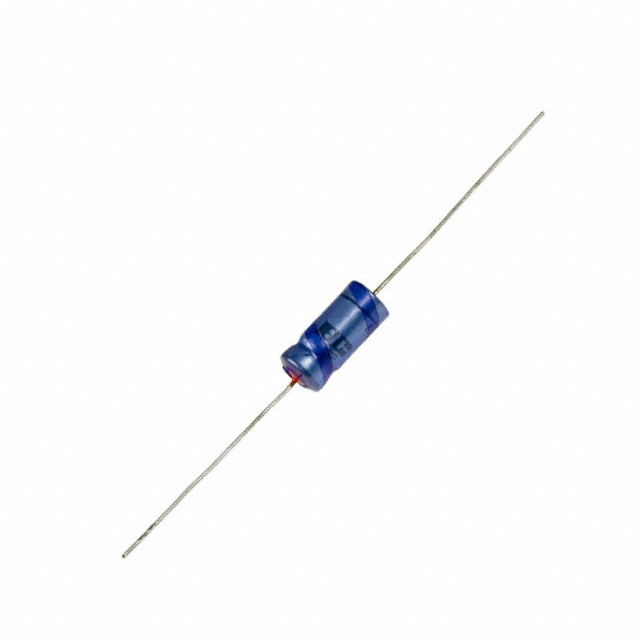
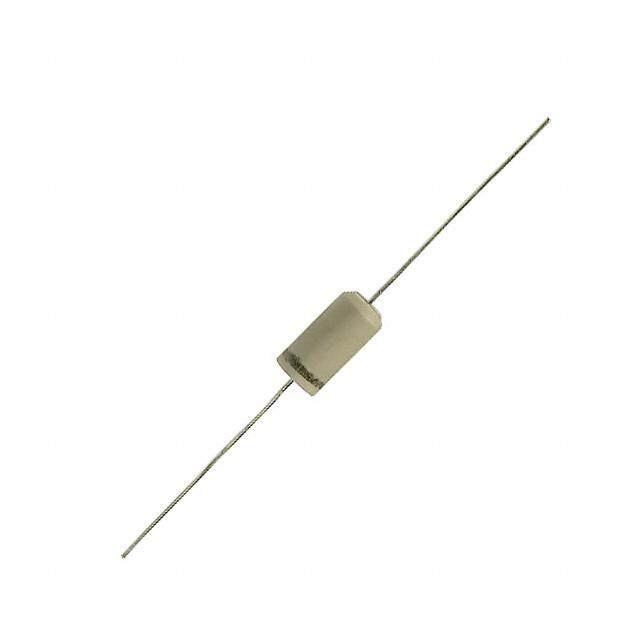
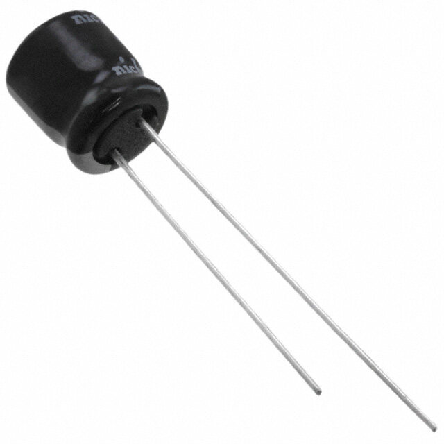
| 描述 | CAP ALUM 10UF 100V 20% AXIAL铝质电解电容器 - 带引线 10uF 100V 20% Axial |
| ESR | 11 Ohms |
| ESR(等效串联电阻) | 11 欧姆 |
| 产品分类 | |
| 品牌 | Vishay / BC ComponentsVishay BC Components |
| 产品手册 | |
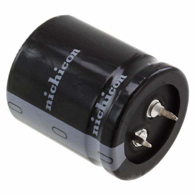
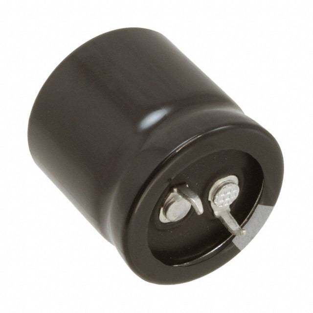
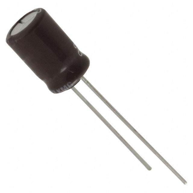
| 产品图片 |
|
| rohs | 符合RoHS无铅 / 符合限制有害物质指令(RoHS)规范要求 |
| 产品系列 | 铝电解电容器,铝质电解电容器 - 带引线,Vishay / BC Components MAL211839109E3AHT 118 |
| 数据手册 | |
| 产品型号 | MAL211839109E3MAL211839109E3 |
| 不同温度时的使用寿命 | 125°C 时为 4000 小时 |
| 产品 | High Temp Electrolytic Capacitors |
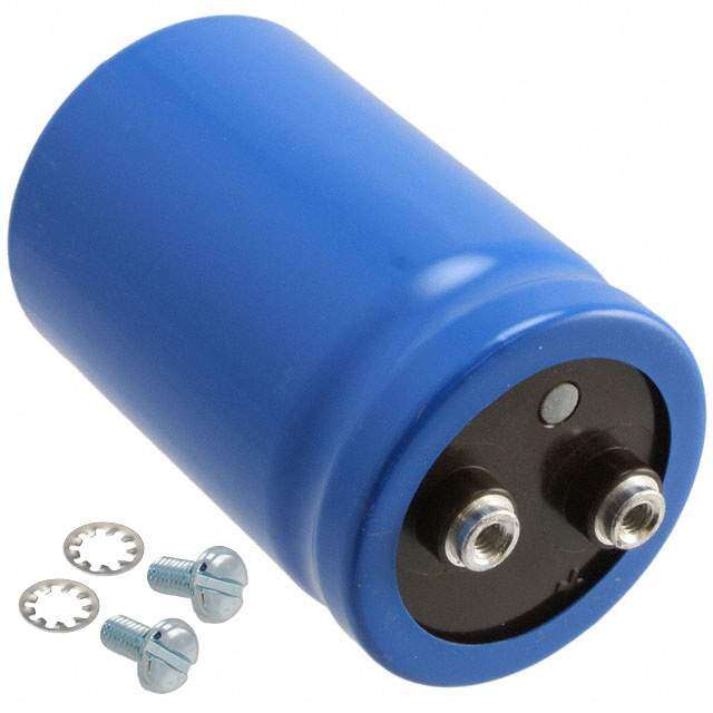
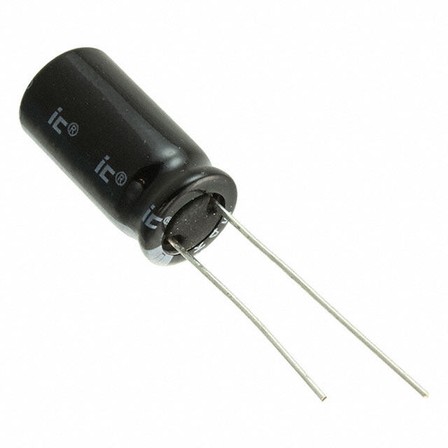
| 产品目录绘图 |
|
| 产品目录页面 | |
| 产品种类 | 铝质电解电容器 - 带引线 |
| 其它名称 | 4163PHCT |
| 包装 | 剪切带 (CT) |
| 商标 | Vishay / BC Components |
| 外壳直径 | 6.5 mm |
| 外壳长度 | 18 mm |
| 大小/尺寸 | 0.256" 直径 x 0.709" 长(6.50mm x 18.00mm) |
| 安装类型 | 通孔 |
| 容差 | 20 %±20% |
| 封装/外壳 | 轴向,CAN |
| 尺寸 | 6.5 mm Dia. x 18 mm L |
| 工作温度 | -40°C ~ 125°C |
| 工厂包装数量 | 1000 |
| 应用 | 通用 |
| 引线间距 | - |
| 最大工作温度 | + 125 C |
| 标准包装 | 1 |
| 电压额定值DC | 100 V |
| 电容 | 10µF10 uF |
| 端接类型 | Axial |
| 类型 | Axial High Temperature Aluminum Capacitors- |
| 系列 | 118 AHT |
| 纹波电流 | 52 mA52mA |
| 表面贴装焊盘尺寸 | - |
| 阻抗 | 9 欧姆 |
| 零件号别名 | 222211839109 |
| 额定电压 | 100V |
| 高度-安装(最大值) | - |


- 商务部:美国ITC正式对集成电路等产品启动337调查
- 曝三星4nm工艺存在良率问题 高通将骁龙8 Gen1或转产台积电
- 太阳诱电将投资9.5亿元在常州建新厂生产MLCC 预计2023年完工
- 英特尔发布欧洲新工厂建设计划 深化IDM 2.0 战略
- 台积电先进制程称霸业界 有大客户加持明年业绩稳了
- 达到5530亿美元!SIA预计今年全球半导体销售额将创下新高
- 英特尔拟将自动驾驶子公司Mobileye上市 估值或超500亿美元
- 三星加码芯片和SET,合并消费电子和移动部门,撤换高东真等 CEO
- 三星电子宣布重大人事变动 还合并消费电子和移动部门
- 海关总署:前11个月进口集成电路产品价值2.52万亿元 增长14.8%

PDF Datasheet 数据手册内容提取
118 AHT www.vishay.com Vishay BCcomponents Aluminum Electrolytic Capacitors Axial High Temperature FEATURES • Polarized aluminum electrolytic capacitors, non-solid electrolyte • Axial leads, cylindrical aluminum case, insulated with a blue sleeve • Mounting ring version not available in insulated form • Taped versions up to case Ø 15 mm x 30 mm available for automatic insertion • Charge and discharge proof 119 AHT-DIN • Extra long useful life: up to 8000 h at 125 °C, high reliability high ripple, • Extended temperature range: 125 °C (usable up to low impedance 150 °C) 118 AHT very high 120 ATC • Miniaturized, high CV-product per unit volume 138 AML 105 °C 125 °C ripple 125 °C • Material categorization: for definitions of compliance Fig. 1 please see www.vishay.com/doc?99912 APPLICATIONS QUICK REFERENCE DATA • Automotive, industrial and telecommunication DESCRIPTION VALUE • Smoothing, filtering, coupling, decoupling, timing Nominal case sizes 6.5 x 18 10 x 30 • For use after very long storage (10 years) without voltage (Ø D x L in mm) to 10 x 25 to 21 x 38 applied Rated capacitance range, C 4.7 μF to 10 000 μF R • Portable and mobile equipment (small size, low mass) Tolerance on C ± 20 % R • Low mounting height boards, vibration and shock Rated voltage range, UR 6.3 V to 200 V resistant -40 °C to -55 °C to • Outdoor applications, e.g. aerial amplifiers Category temperature range +125 °C +125 °C Endurance test at 150 °C MARKING 500 h 500 h (6.3 V to 100 V) The capacitors are marked (where possible) with the Endurance test at 125 °C 2000 h 3000 h following information: Useful life at 125 °C 4000 h 8000 h • Rated capacitance (in μF) Useful life at 40 °C, • Tolerance on rated capacitance, code letter in accordance 500 000 h 1 000 000 h 1.8 x I applied with IEC 60062 (M for ± 20 %) R Shelf life at 0 V, 125 °C: • Rated voltage (in V) at 125 °C and 85 °C U = 6.3 V to 63 V 500 h • Date code, in accordance with IEC 60062 R U = 100 V and 200 V 100 h • Code indicating factory of origin R Based on sectional • Name of manufacturer IEC 60 384-4 / EN130 300 specification • Negative terminal identification Climatic category IEC 60068 40 / 125 / 56 55 / 125 / 56 • Series number (118) Revision: 20-Apr-17 1 Document Number: 28334 For technical questions, contact: aluminumcaps1@vishay.com THIS DOCUMENT IS SUBJECT TO CHANGE WITHOUT NOTICE. THE PRODUCTS DESCRIBED HEREIN AND THIS DOCUMENT ARE SUBJECT TO SPECIFIC DISCLAIMERS, SET FORTH AT www.vishay.com/doc?91000
118 AHT www.vishay.com Vishay BCcomponents SELECTION CHART FOR C , U , AND RELEVANT NOMINAL CASE SIZES (Ø D x L in mm) R R CR UR (V) (μF) 6.3 10 16 25 40 63 100 200 4.7 - - - - - 6.5 x 18 6.5 x 18 - 10 - - - - - 6.5 x 18 6.5 x 18 - 15 - - - - - - - 10 x 30 22 - - - - - 6.5 x 18 8 x 18 12.5 x 30 33 - - - - - - 10 x 25 15 x 30 - - - - 6.5 x 18 8 x 18 10 x 25 18 x 30 47 - - - - - - 10 x 30 - 68 - - - - - - 12.5 x 30 18 x 38 - - - 6.5 x 18 8 x 18 10 x 25 12.5 x 30 21 x 38 100 - - - - - 10 x 30 - - 150 - - - - 10 x 18 12.5 x 30 15 x 30 - - 6.5 x 18 8 x 18 10 x 18 10 x 25 12.5 x 30 18 x 30 - 220 - - - - 10 x 30 - - - 330 - 8 x 18 10 x 18 10 x 25 12.5 x 30 15 x 30 18 x 38 - - 8 x 18 10 x 18 10 x 25 12.5 x 30 18 x 30 21 x 38 - 470 - - - 10 x 30 - - - - 680 - - 10 x 30 12.5 x 30 15 x 30 18 x 38 - - 10 x 18 10 x 25 12.5 x 30 12.5 x 30 18 x 30 21 x 38 - - 1000 - 10 x 30 - - - - - - 1500 10 x 25 12.5 x 30 12.5 x 30 15 x 30 18 x 38 - - - 2200 - 12.5 x 30 15 x 30 18 x 30 21 x 38 - - - 3300 - 15 x 30 18 x 30 18 x 38 - - - - 4700 - 18 x 30 18 x 38 21 x 38 - - - - 6800 - 18 x 38 21 x 38 - - - - - 10 000 - 21 x 38 - - - - - - DIMENSIONS in millimeters AND AVAILABLE FORMS 73 ± 1.6 Ø D L I L 33 ± 1 Ø d Ø d Ø D F F Form BR: Taped on reel Form AA: Axial in box Case Ø D x L = 6.5 mm x 18 mm to 15 mm x 30 mm Case Ø D x L = 10 mm x 30 mm to 21 mm x 38 mm Form BA: Taped in box (ammopack) Case Ø D x L = 6.5 mm x 18 mm to 10 mm x 25 mm Fig. 2 - Forms BA and BR Fig. 3 - Form AA Revision: 20-Apr-17 2 Document Number: 28334 For technical questions, contact: aluminumcaps1@vishay.com THIS DOCUMENT IS SUBJECT TO CHANGE WITHOUT NOTICE. THE PRODUCTS DESCRIBED HEREIN AND THIS DOCUMENT ARE SUBJECT TO SPECIFIC DISCLAIMERS, SET FORTH AT www.vishay.com/doc?91000
118 AHT www.vishay.com Vishay BCcomponents Table 1 AXIAL; DIMENSIONS in millimeters, MASS AND PACKAGING QUANTITIES NOMINAL AXIAL: FORM AA, BA AND BR PACKAGING QUANTITIES CASE MASS CASE SIZE FORM FORM FORM CODE Ø d I Ø D L F (g) Ø D x L max. max. min. AA BA BR 6.5 x 18 4 0.8 - 6.9 18.5 25 1.3 - 1000 1000 8 x 18 5 0.8 - 8.5 18.5 25 1.7 - 500 500 10 x 18 6 0.8 - 10.5 18.5 25 2.5 - 500 500 10 x 25 7 0.8 - 10.5 25.5 30 3.3 - 500 500 10 x 30 00 0.8 55 ± 1 10.5 30.5 35 4.8 340 - 500 12.5 x 30 01 0.8 55 ± 1 13.0 30.5 35 7.4 260 - 400 15 x 30 02 0.8 55 ± 1 15.5 30.5 35 11.7 200 - 250 18 x 30 03 0.8 55 ± 1 18.5 30.5 35 12.9 120 - - 18 x 38 04 0.8 34 ± 1 18.5 39.5 44 19 125 - - 21 x 38 05 0.8 34 ± 1 21.5 39.5 44 24 100 - - Note • Detailed tape dimensions see section “Packaging”. D 120 °C (3 x) + 0.2 3.6 D3 - 0.2 90° ± 2° L - (3 x) 1.05 + 0.03(3 x) - 0.1 d2 1.3 +- 0 0 .05(3 x) 1.3 + 0.10(3 x) 1+ 1.0 - 0.5 Mounting holes Ø d1 Case Ø D x L = 15 mm x 30 mm to 21 mm x 38 mm Especially for applications with severe shocks and vibrations Ø D2 Fig. 4 - Mounting hole diagram and outline; Form MR: With mounting ring and pins MOUNTING RING; DIMENSIONS in millimeters, MASS AND PACKAGING QUANTITIES NOMINAL MOUNTING RING: FORM MR CASE MASS PACKAGING CASE SIZE Ø D x L CODE Ø d1 Ø d2 Ø Dmax. Ø D2max. D3 Lmax. (g) QUANTITIES 15 x 30 02 0.8 1.0 + 0.4 15.5 17.5 16.5 ± 0.2 33 8.6 200 18 x 30 03 0.8 1.0 + 0.4 18.5 19.5 18.5 ± 0.2 33 11.5 240 18 x 38 04 0.8 1.0 + 0.4 18.5 19.5 18.5 ± 0.2 42 14.0 100 21 x 38 05 0.8 1.0 + 0.4 21.5 22.5 21.5 ± 0.2 42 19.0 100 ORDERING EXAMPLE ELECTRICAL DATA Electrolytic capacitor 118 series SYMBOL DESCRIPTION C Rated capacitance at 100 Hz, tolerance ± 20 % 1000 μF / 10 V; ± 20 % R IR Rated RMS ripple current at 100 Hz, 125 °C Nominal case size: Ø 10 mm x 30 mm; Form BR I Max. leakage current after 1 min at U L1 R Ordering code: MAL211824102E3 I Max. leakage current after 5 min at U L5 R Former 12NC: 2222 118 24102 tan Max. dissipation factor at 100 Hz Equivalent series resistance at 100 Hz ESR (calculated from tan max. and CR) Z Max. impedance at 10 kHz Note • Unless otherwise specified, all electrical values in Table 2 apply at T = 20 °C, P = 86 kPa to 106 kPa, RH = 45 % to 75 %. amb Revision: 20-Apr-17 3 Document Number: 28334 For technical questions, contact: aluminumcaps1@vishay.com THIS DOCUMENT IS SUBJECT TO CHANGE WITHOUT NOTICE. THE PRODUCTS DESCRIBED HEREIN AND THIS DOCUMENT ARE SUBJECT TO SPECIFIC DISCLAIMERS, SET FORTH AT www.vishay.com/doc?91000
118 AHT www.vishay.com Vishay BCcomponents Table 2 ELECTRICAL DATA AND ORDERING INFORMATION NOMINAL I ORDERING CODE MAL2118....... C R I I ESR Z U(VR) 10(μ0F RH)z CAØ(S mDEm xS )ILZE CCOADSEE 11(02m05 A H°)Cz 1( μmLA1i)n 5( μmLA5i)n 1t0a0n H z 10(0 H) z 10( kH) z FOINR BMO AXA FOOTNAR RPMEE BDELR FOITNAR BPMOE DBXA MFOORURIMNNTG MINRG 1000 10 x 18 6 251 42 17 0.50 0.790 0.80 - 23102E3 33102E3 - 6.3 1500 10 x 25 7 352 61 23 0.50 0.530 0.53 - 90502E3 90503E3 - 220 6.5 x 18 4 109 20 8.4 0.35 2.530 2.10 - 24221E3 34221E3 - 330 8 x 18 5 150 24 11 0.35 1.690 1.40 - 24331E3 34331E3 - 470 8 x 18 5 179 32 13 0.35 1.190 1.00 - 24471E3 34471E3 - 1000 10 x 25 7 343 64 24 0.35 0.560 0.55 - 90504E3 90505E3 - 1000 10 x 30 00 550 64 24 0.32 0.505 0.45 14102E3 24102E3 - - 10 1500 12.5 x 30 01 740 94 34 0.32 0.340 0.28 14152E3 24152E3 - - 2200 12.5 x 30 01 830 136 48 0.40 0.290 0.27 14222E3 24222E3 - - 3300 15 x 30 02 1070 202 70 0.40 0.190 0.18 14332E3 24332E3 - 44332E3 4700 18 x 30 03 1350 286 98 0.46 0.155 0.15 14472E3 - - 44472E3 6800 18 x 38 04 1730 412 140 0.53 0.100 0.10 14682E3 - - 44682E3 10 000 21 x 38 05 1860 604 200 0.53 0.084 0.10 14103E3 - - 44103E3 220 8 x 18 5 145 25 11 0.25 1.810 1.50 - 25221E3 35221E3 - 330 10 x 18 6 204 36 15 0.25 1.210 1.20 - 25331E3 35331E3 - 470 10 x 18 6 243 49 19 0.25 0.850 0.83 - 25471E3 35471E3 - 680 10 x 30 00 510 69 30 0.22 0.525 0.45 15681E3 25681E3 - - 1000 12.5 x 30 01 720 100 36 0.22 0.345 0.28 15102E3 25102E3 - - 16 1500 12.5 x 30 01 790 148 52 0.29 0.305 0.27 15152E3 25152E3 - - 2200 15 x 30 02 1010 215 74 0.29 0.205 0.18 15222E3 25222E3 - 45222E3 3300 18 x 30 03 1300 321 110 0.34 0.165 0.15 15332E3 - - 45332E3 4700 18 x 38 04 1670 455 150 0.34 0.105 0.10 15472E3 - - 45472E3 6800 21 x 38 05 1790 657 220 0.38 0.088 0.10 15682E3 - - 45682E3 100 6.5 x 18 4 102 20 9 0.18 2.860 2.30 - 26101E3 36101E3 - 220 10 x 18 6 196 37 15 0.18 1.300 1.25 - 26221E3 36221E3 - 330 10 x 25 7 274 54 21 0.18 0.870 0.82 - 26331E3 36331E3 - 470 10 x 25 7 327 75 28 0.18 0.610 0.57 - 90508E3 90509E3 - 470 10 x 30 00 490 75 28 0.18 0.610 0.50 16471E3 26471E3 - - 25 680 12.5 x 30 01 680 106 38 0.18 0.420 0.30 16681E3 26681E3 - - 1000 12.5 x 30 01 760 154 54 0.24 0.375 0.28 16102E3 26102E3 - - 1500 15 x 30 02 980 229 79 0.25 0.263 0.22 16152E3 26152E3 - 46152E3 2200 18 x 30 03 1240 334 110 0.26 0.185 0.17 16222E3 - - 46222E3 3300 18 x 38 04 1610 499 170 0.26 0.120 0.11 16332E3 - - 46332E3 4700 21 x 38 05 1710 709 240 0.28 0.095 0.10 16472E3 - - 46472E3 47 6.5 x 18 4 89.8 20 7.8 0.11 3.720 2.80 - 27479E3 37479E3 - 100 8 x 18 5 147 28 12 0.11 1.750 1.30 - 27101E3 37101E3 - 150 10 x 18 6 207 40 16 0.11 1.170 1.00 - 27151E3 37151E3 - 220 10 x 25 7 287 57 22 0.11 0.800 0.68 - 90511E3 90512E3 - 220 10 x 30 00 390 57 22 0.10 0.700 0.55 17221E3 27221E3 - - 40 330 12.5 x 30 01 570 83 30 0.10 0.430 0.33 17331E3 27331E3 - - 470 12.5 x 30 01 620 117 42 0.11 0.380 0.30 17471E3 27471E3 - - 680 15 x 30 02 810 167 58 0.11 0.255 0.23 17681E3 27681E3 - 47681E3 1000 18 x 30 03 1070 244 84 0.13 0.205 0.18 17102E3 - - 47102E3 1500 18 x 38 04 1390 364 120 0.13 0.130 0.11 17152E3 - - 47152E3 2200 21 x 38 05 1540 532 180 0.15 0.105 0.10 17222E3 - - 47222E3 Revision: 20-Apr-17 4 Document Number: 28334 For technical questions, contact: aluminumcaps1@vishay.com THIS DOCUMENT IS SUBJECT TO CHANGE WITHOUT NOTICE. THE PRODUCTS DESCRIBED HEREIN AND THIS DOCUMENT ARE SUBJECT TO SPECIFIC DISCLAIMERS, SET FORTH AT www.vishay.com/doc?91000
118 AHT www.vishay.com Vishay BCcomponents ELECTRICAL DATA AND ORDERING INFORMATION NOMINAL I ORDERING CODE MAL2118....... C R I I ESR Z U(VR) 10(μ0F RH)z CAØ(S mDEm xS )ILZE CCOADSEE 11(02m05 A H°)Cz 1( μmLA1i)n 5( μmLA5i)n 1t0a0n H z 10(0 H) z 10( kH) z FOINR BMO AXA FOOTNAR RPMEE BDELR FOITNAR BPMOE DBXA MFOORURIMNNTG MINRG 4.7 6.5 x 18 4 35.6 20 4.6 0.07 24.0 8.90 - 28478E3 38478E3 - 10 6.5 x 18 4 51.9 20 5.3 0.07 11.0 5.60 - 28109E3 38109E3 - 22 6.5 x 18 4 77.0 20 6.8 0.07 5.10 3.20 - 28229E3 38229E3 - 47 8 x 18 5 126 22 9.9 0.07 2.40 1.50 - 28479E3 38479E3 - 100 10 x 25 7 243 42 17 0.07 1.10 0.70 - 90513E3 90514E3 - 100 10 x 30 00 340 42 17 0.07 1.91 1.62 18101E3 28101E3 - - 63 150 12.5 x 30 01 490 61 23 0.07 1.00 0.79 18151E3 28151E3 - - 220 12.5 x 30 01 550 87 32 0.08 0.94 0.82 18221E3 28221E3 - - 330 15 x 30 02 730 129 46 0.09 0.63 0.56 18331E3 28331E3 - 48331E3 470 18 x 30 03 970 182 63 0.09 0.44 0.39 18471E3 - - 48471E3 680 18 x 38 04 1230 261 90 0.09 0.30 0.26 18681E3 - - 48681E3 1000 21 x 38 05 1400 383 130 0.10 0.16 0.20 18102E3 - - 48102E3 4.7 6.5 x 18 4 36 20 4.9 0.07 24.0 19.0 - 29478E3 39478E3 - 10 6.5 x 18 4 52 20 6.0 0.07 11.0 9.00 - 29109E3 39109E3 - 22 8 x 18 5 91 20 8.4 0.07 5.10 4.00 - 29229E3 39229E3 - 33 10 x 25 7 140 24 11 0.07 3.40 2.70 - 29339E3 39339E3 - 47 10 x 25 7 170 33 13 0.07 2.60 2.00 - 90535E3 90536E3 - 47 10 x 30 00 240 33 13 0.08 2.60 2.00 19479E3 29479E3 - - 100 68 12.5 x 30 01 320 45 18 0.08 1.80 1.20 19689E3 29689E3 - - 100 12.5 x 30 01 380 64 24 0.09 1.40 1.15 19101E3 29101E3 - - 150 15 x 30 02 500 94 34 0.10 0.94 0.78 19151E3 29151E3 - 49151E3 220 18 x 30 03 690 136 48 0.10 0.66 0.55 19221E3 - - 49221E3 330 18 x 38 04 890 202 70 0.10 0.45 0.37 19331E3 - - 49331E3 470 21 x 38 05 1050 286 98 0.10 0.33 0.28 19471E3 - - 49471E3 15 10 x 30 00 150 22 10 0.046 4.76 3.75 92159E3 90012E3 - - 22 12.5 x 30 01 210 31 13 0.046 3.17 2.22 92229E3 90013E3 - - 33 15 x 30 02 290 44 17 0.046 2.11 1.11 92339E3 90014E3 - 90002E3 200 47 18 x 30 03 390 61 23 0.046 1.48 0.60 92479E3 - - 90003E3 68 18 x 38 04 500 86 31 0.046 1.02 0.42 92689E3 - - 90004E3 100 21 x 38 05 610 124 44 0.046 0.96 0.39 92101E3 - - 90005E3 Revision: 20-Apr-17 5 Document Number: 28334 For technical questions, contact: aluminumcaps1@vishay.com THIS DOCUMENT IS SUBJECT TO CHANGE WITHOUT NOTICE. THE PRODUCTS DESCRIBED HEREIN AND THIS DOCUMENT ARE SUBJECT TO SPECIFIC DISCLAIMERS, SET FORTH AT www.vishay.com/doc?91000
118 AHT www.vishay.com Vishay BCcomponents ADDITIONAL ELECTRICAL DATA VALUE PARAMETER CONDITIONS AXIAL MOUNTING RING Voltage Surge voltage Us 1.15 x UR Reverse voltage Urev 1 V Current After 1 min at U IL1 0.006 CR x UR + 4 μA or 20 μA Leakage current R (whichever is greater) After 5 min at UR IL5 0.002 CR x UR + 4 μA Inductance Case Ø D x L mm: 6.5 x 18 Typ. 15 nH - 8 x 18 Typ. 35 nH - 10 x 18 Typ. 69 nH - 10 x 25 Typ. 38 nH - Equivalent series inductance (ESL) 10 x 30 Typ. 38 nH - 12.5 x 30 Typ. 46 nH - 15 x 30 Typ. 48 nH Typ. 39 nH 18 x 30 Typ. 50 nH Typ. 39 nH 18 x 38 Typ. 54 nH Typ. 39 nH 21 x 38 Typ. 59 nH Typ. 39 nH Table 3 UPRATING VALUES AT REDUCED AMBIENT TEMPERATURE SYMBOL CONDITIONS VALUES UNIT U T > 85 °C to 125 °C 6.3 10 16 25 40 63 100 200 V R amb UR2 Tamb 85 °C 10 16 25 40 63 100 125 250 V Note • For applications at ambient temperatures of 85 °C, the rated voltage (UR) may be raised to UR2. CAPACITANCE 102 1.2 Curve 1: 63 V C 4 ESR 2 Curve 2: 6.3 V C0 ESR 1.1 1 0 1 10 1.0 0.9 1 2 1 0.8 3 Curve 1: 100 V; 200 V 0.7 Curve 2: 40 V; 63 V Curve 3: 16 V; 25 V 4 Curve 4: 6.3 V; 10 V 10-1 0.6 -50 0 50 100 -60 -40 -20 0 20 40 60 80 100 120 140 160 Case Ø D x L = 6.5 mm x 18 mm to 10 mm x 25 mm Tamb (°C) Case Ø D x L = 10 mm x 30 mm to 21 mm x 38 mm Tamb (°C) C0 = Capacitance at 20 °C, 100 Hz C0 = Capacitance at 20 °C, 100 Hz Fig. 5 - Typical multiplier of capacitance Fig. 6 - Typical multiplier of capacitance as a function of ambient temperature as a function of ambient temperature Revision: 20-Apr-17 6 Document Number: 28334 For technical questions, contact: aluminumcaps1@vishay.com THIS DOCUMENT IS SUBJECT TO CHANGE WITHOUT NOTICE. THE PRODUCTS DESCRIBED HEREIN AND THIS DOCUMENT ARE SUBJECT TO SPECIFIC DISCLAIMERS, SET FORTH AT www.vishay.com/doc?91000
118 AHT www.vishay.com Vishay BCcomponents 1.2 1.1 C C C C 8 01.0 01.0 1 1 1 2 0.8 0.9 3 4 0.6 3 2 0.8 Curve 1: 200 V 5 Curve 1: 63 V to 200 V (< 15 µF) 4 Curve 2: 100 V 6 0.4 CCuurrvvee 23:: 6430 VV; 100 V (< 15 µF) 56 0.7 CCuurrvvee 34:: 6430 VV 7 Curve 4: 25 V Curve 5: 25 V 0.2 Curve 5: 16 V 7 0.6 Curve 6: 16 V 8 Curve 6: 10 V Curve 7: 10 V Curve 7: 6.3 V Curve 8: 6.3 V 0 0.5 10 102 103 104 f (Hz) 105 10 102 103 f (Hz) 104 Case Ø D x L = 6.5 mm x 18 mm to 10 mm x 25 mm Case Ø D x L = 10 mm x 30 mm to 21 mm x 38 mm C = Capacitance at 20 °C, 100 Hz C = Capacitance at 20 °C, 100 Hz 0 0 Fig. 7 - Typical multiplier of capacitance Fig. 8 - Typical multiplier of capacitance as a function of frequency as a function of frequency EQUIVALENT SERIES RESISTANCE (ESR) 102 102 Curve 1: 100 V; 200 V 3 Curve 1: 6.3 V to 10 V; 16 V EESSRR0 CCuurrvvee 23:: 265.3 V V; ;4 100 V V; ;6 136 V V EESSRR0 12 CCuurrvvee 23:: 2150 0V V; 4; 02 0V0; V63 V 10 10 1 3 1 1 2 2 3 1 10-1 10-1 -100 -50 0 50 100 150 -100 -50 0 50 100 150 Case Ø D x L = 6.5 mm x 18 mm to 10 mm x 25 mm Tamb (°C) Case Ø D x L = 18 mm x 30 mm to 21 mm x 38 mm Tamb (°C) ESR = Typical at 20 °C, 100 Hz 0 ESR = Typical at 20 °C, 100 Hz 0 Fig. 9 - Typical multiplier of ESR Fig. 10 - Typical multiplier of ESR as a function of ambient temperature as a function of ambient temperature 2.0 1.6 ESR Curve 1: 63 V to 100 V (< 15 µF) 1 Curve 1: 200 V ESR10.6 1 CCCuuurrrvvveee 243::: 4620.53 VV V ; 10 V; 16 V EESSR1R.02 23 CCCuuurrrvvveee 234::: 1410060 VV V;; 6235 VV 2 45 Curve 5: 6.3 V; 10 V 3 1.2 4 0.8 5 4 0.8 4 3 33 2 2 1 0.4 0.4 1 0 0 10 102 103 104 f (Hz) 105 10 102 103 104 f (Hz) 105 Case Ø D x L = 6.5 mm x 18 mm to 10 mm x 25 mm Case Ø D x L = 10 mm x 30 mm to 21 mm x 38 mm ESR = Typical at 20 °C, 100 Hz ESR = Typical at 20 °C, 100 Hz 0 0 Fig. 11 - Typical multiplier of ESR Fig. 12 - Typical multiplier of ESR as a function of frequency as a function of frequency Revision: 20-Apr-17 7 Document Number: 28334 For technical questions, contact: aluminumcaps1@vishay.com THIS DOCUMENT IS SUBJECT TO CHANGE WITHOUT NOTICE. THE PRODUCTS DESCRIBED HEREIN AND THIS DOCUMENT ARE SUBJECT TO SPECIFIC DISCLAIMERS, SET FORTH AT www.vishay.com/doc?91000
118 AHT www.vishay.com Vishay BCcomponents IMPEDANCE (Z) 103 103 Z Curve 1: 47 V Z Curve 1: 100 V (Ω) Curve 2: 100 V (Ω) Curve 2: 220 V Curve 3: 220 V Curve 3: 470 V 102 Curve 4: 470 V 102 Curve 4: 1000 V 1 2 1 10 10 3 2 4 3 4 1 1 10-1 10-1 102 103 104 105 f (Hz) 106 102 103 104 105 f (Hz) 106 Case Ø D x L = 8 mm x 18 mm Tamb (°C) Case Ø D x L = 10 mm x 25 mm Tamb (°C) Fig. 13 - Typical impedance as a function of frequency Fig. 14 - Typical impedance as a function of frequency 103 103 Curve 1: 22 µF, 200 V Curve 1: 22 µF, 200 V Curve 7: 680 µF, 25 V (ΩZ) 1 CCuurrvvee 23:: 6185 0µ µF,F ,1 6030 VV (ΩZ) 1 CCuurrvvee 23:: 6185 0µ µF,F 1, 0603 VVCCuurrvvee 89:: 11050000 µµFF,, 2156 VV 102 2 CCuurrvvee 45:: 232300 µµFF,, 6430 VV 102 2 CCuurrvvee 45:: 232300 µµFF,, 6430 VVCanudrv 2e2 1000: µ1F5,0 60. 3µ FV, 10 V 34 Curve 6: 470 µF, 40 V 3 Curve 6: 470 µF, 40 VCurve 11: 3300 µF, 6.3 V 5 Curve 7: 680 µF, 25 V 4 10 67 Curve 8: 1000 µF, 25 V 10 56 8 and 1000 µF, 16 V 7 9 8 10 9 11 10 11 1 1 Curve 9: 1500 µF, 16 V and 1500 µF, 10 V Curve 10: 1500 µF, 10 V and 2200 µF, 6.3 V Curve 11: 3300 µF, 6.3 V 10-1 10-1 f (Hz) f (Hz) 10 102 103 104 105 106 107 10 102 103 104 105 106 107 Case Ø D x L = 18 mm x 30 mm T (40 °C) Case Ø D x L = 12.5 mm x 30 mm T (20 °C) amb amb Fig. 15 - Typical impedance as a function of frequency Fig. 16 - Typical impedance as a function of frequency 103 102 Curve 1: 47 µF, 200 V 1 Curve 1: 47 µF, 200 V (ΩZ) CCuurrvvee 23:: 242700 µµFF,, 16030 V V (Ω Z ) 2 CCuurrvvee 23:: 242700 µµFF,, 16030 V V 102 1 Curve 4: 1000 µF, 40 V 10 3 Curve 4: 1000 µF, 40 V Curve 5: 2200 µF, 25 V 4 Curve 5: 2200 µF, 25 V Curve 6: 3300 µF, 18 V Curve 6: 3300 µF, 18 V 2 Curve 7: 4700 µF, 10 V 5 Curve 7: 4700 µF, 10 V 10 3 Curve 8: 6800 µF, 6.3 V 1 67 Curve 8: 6800 µF, 6.3 V 8 4 5 6 7 1 8 10-1 10-1 10-2 10 102 103 104 105 106f (Hz)107 10 102 103 104 105 106f (Hz)107 Case Ø D x L = 18 mm x 30 mm T (40 °C) Case Ø D x L = 18 mm x 30 mm T (20 °C) amb amb Fig. 17 - Typical impedance as a function of frequency Fig. 18 - Typical impedance as a function of frequency Revision: 20-Apr-17 8 Document Number: 28334 For technical questions, contact: aluminumcaps1@vishay.com THIS DOCUMENT IS SUBJECT TO CHANGE WITHOUT NOTICE. THE PRODUCTS DESCRIBED HEREIN AND THIS DOCUMENT ARE SUBJECT TO SPECIFIC DISCLAIMERS, SET FORTH AT www.vishay.com/doc?91000
118 AHT www.vishay.com Vishay BCcomponents RIPPLE CURRENT AND USEFUL LIFE Table 4 ENDURANCE TEST DURATION AND USEFUL LIFE NOMINAL CASE SIZE ENDURANCE USEFUL LIFE Ø D x L AT 125 °C AT 125 °C (mm) (h) (h) 6.5 x 18 2000 4000 8 x 18 2000 4000 10 x 18 2000 4000 10 x 25 2000 4000 10 x 30 3000 8000 12.5 x 30 3000 8000 15 x 30 3000 8000 18 x 30 3000 8000 18 x 38 3000 8000 21 x 38 3000 8000 Note • Multiplier of useful life code: MBC242 MBC242 I 4.3 A IR 4.2 4.1 4.0 3.9 3.8 3.7 3.6 3.5 3.4 3.3 3.2 3.1 3.0 Lifetime multiplier 2.8 1.0 2.6 1.5 2.0 2.4 2.2 4.03.0 2.0 8.06.0 1.8 2012 IA = Actual ripple current at 100 Hz 1.6 30 I(R1 )= U Rsaetfeudl l irfiep palte 1 c2u5r r°eCn ta antd 1 I0R0 a pHpzl,i e1d2:5 °C 11..42 10060 (1) C1C0aa ssmeem ØØ xDD 2 xx5 LLm ==m 61: .045 0 mm0m0m h xx 3108 mmmm ttoo 1000....0850 400200 21 mm x 38 mm: 8000 h 40 50 60 70 80 90 100 110 120 130 T (°C) amb Fig. 19 - Multiplier of useful life as a function of ambient temperature and ripple current load Revision: 20-Apr-17 9 Document Number: 28334 For technical questions, contact: aluminumcaps1@vishay.com THIS DOCUMENT IS SUBJECT TO CHANGE WITHOUT NOTICE. THE PRODUCTS DESCRIBED HEREIN AND THIS DOCUMENT ARE SUBJECT TO SPECIFIC DISCLAIMERS, SET FORTH AT www.vishay.com/doc?91000
118 AHT www.vishay.com Vishay BCcomponents Table 5 MULTIPLIER OF RIPPLE CURRENT (I ) AS A FUNCTION OF FREQUENCY R FREQUENCY (Hz) U R 50 100 300 1000 3000 10 000 (V) I MULTIPLIER R 6.3 0.95 1.00 1.07 1.12 1.15 1.20 10 0.95 1.00 1.07 1.12 1.15 1.20 16 0.95 1.00 1.07 1.12 1.15 1.20 25 0.95 1.00 1.07 1.12 1.15 1.20 40 0.90 1.00 1.12 1.20 1.25 1.30 63 0.90 1.00 1.12 1.20 1.25 1.30 100 0.85 1.00 1.20 1.30 1.35 1.40 200 0.85 1.00 1.20 1.30 1.35 1.40 Table 6 TEST PROCEDURES AND REQUIREMENTS TEST PROCEDURE REQUIREMENTS NAME OF TEST REFERENCE (quick reference) IEC 60384-4 / CTaamsbe =s i1z2es5: °C; UR applied; UURR > 66..33 VV;; CC//CC:: +±1 155 % % / -30 % Endurance EN130300 tan 1.3 x spec. limit 6.5 mm x 18 mm to 10 mm x 25 mm: 2000 h; subclause 4.13 Z 2 x spec. limit 10 mm x 30 mm to 21 mm x 38 mm: 3000 h IL5 spec. limit UR 6.3 V; C/C: +45 % / -50 % UR > 6.3 V; C/C: ± 45 % Tamb = 125 °C; UR and IR applied; tan 3 x spec. limit Case Ø D x L = 6.5 mm x 18 mm to 10 mm x 25 mm: CECC 30301 Z 3 x spec. limit Useful life 4000 h subclause 1.8.1 Case Ø D x L = 10 mm x 30 mm to 21 mm x 38 mm: IL5 spec. limit 8000 h no short or open circuit total failure percentage: 1 % (200 V 3 %) Tamb = 125 °C; no voltage applied; C/C, tan , Z: Shelf life IEC 60384-4 / UR = 6.3 V to 63 V: 500 h; for requirements (storage at high EN130300 UR = 100 V and 200 V: 100 h see “Endurance test” above temperature) subclause 4.17 A24ft ehr ttoe s4t8: Uh Rb teof obree ampepaliseudr efomre 3n0t min, IL5 2 x spec. limit IEC 60384-4 / Tamb = 125 °C: C/C: ± 20 % Reverse voltage EN130300 125 h at U = -1 V tan spec. limit subclause 4.15 followed by 125 h at UR IL5 spec. limit Statements about product lifetime are based on calculations and internal testing. They should only be interpreted as estimations. Also due to external factors, the lifetime in the field application may deviate from the calculated lifetime. In general, nothing stated herein shall be construed as a guarantee of durability. Revision: 20-Apr-17 10 Document Number: 28334 For technical questions, contact: aluminumcaps1@vishay.com THIS DOCUMENT IS SUBJECT TO CHANGE WITHOUT NOTICE. THE PRODUCTS DESCRIBED HEREIN AND THIS DOCUMENT ARE SUBJECT TO SPECIFIC DISCLAIMERS, SET FORTH AT www.vishay.com/doc?91000
Legal Disclaimer Notice www.vishay.com Vishay Disclaimer ALL PRODUCT, PRODUCT SPECIFICATIONS AND DATA ARE SUBJECT TO CHANGE WITHOUT NOTICE TO IMPROV E RELIABILITY, FUNCTION OR DESIGN OR OTHERWISE. Vishay Intertechnology, Inc., its affiliates, agents, and employees, and all persons acting on its or their behalf (collectively, “Vishay”), disclaim any and all liability for any errors, inaccuracies or incompleteness contained in any datasheet or in any other disclosure relating to any product. Vishay makes no warranty, representation or guarantee regarding the suitability of the products for any particular purpose o r the continuing production of any product. To the maximum extent permitted by applicable law, Vishay disclaims (i) any and all liability arising out of the application or use of any product, (ii) any and all liability, including without limitation special, consequential or incidental damages, and (iii) any and all implied warranties, including warranties of fitness for particular purpose, non-infringement and merchantability. Statements regarding the suitability of products for certain types of applications are based on Vishay’s knowledge of typical requirements that are often placed on Vishay products in generic applications. Such statements are not binding statements about the suitability of products for a particular application. It is the customer’s responsibility to validate that a particular product with the properties described in the product specification is suitable for use in a particular application. Parameters provided in datasheets and / or specifications may vary in different applications and performance may vary over time. All operating parameters, including typical parameters, must be validated for each customer application by the customer’s technical experts. Product specifications do not expand or otherwise modify Vishay’s terms and conditions of purchase, including but not limited to the warranty expressed therein. Except as expressly indicated in writing, Vishay products are not designed for use in medical, life-saving, or life-sustainin g applications or for any other application in which the failure of the Vishay product could result in personal injury or death. Customers using or selling Vishay products not expressly indicated for use in such applications do so at their own risk . Please contact authorized Vishay personnel to obtain written terms and conditions regarding products designed for such applications. No license, express or implied, by estoppel or otherwise, to any intellectual property rights is granted by this documen t or by any conduct of Vishay. Product names and markings noted herein may be trademarks of their respective owners. © 2019 VISHAY INTERTECHNOLOGY, INC. ALL RIGHTS RESERVED Revision: 01-Jan-2019 1 Document Number: 91000
Mouser Electronics Authorized Distributor Click to View Pricing, Inventory, Delivery & Lifecycle Information: V ishay: 2222-118-18102 MAL211818471E3 MAL211816472E3 2222-118-28101 2222-118-28221 MAL211834471E3 MAL211835331E3 MAL211835471E3 MAL211836101E3 MAL211836221E3 MAL211836331E3 MAL211890509E3 MAL211816102E3 MAL211816222E3 MAL211816332E3 MAL211837479E3 MAL211837101E3 MAL211837151E3 MAL211817221E3 MAL211817471E3 MAL211817681E3 MAL211817102E3 MAL211828109E3 MAL211838229E3 MAL211838479E3 MAL211890514E3 MAL211818101E3 MAL211818221E3 MAL211818331E3 MAL211839109E3 MAL211839229E3 MAL211890536E3 MAL211890535E3 MAL211819221E3 MAL211890543E3 MAL211892229E3 MAL211892339E3 MAL211819221 MAL211818102E3 MAL211818681E3 MAL211890505E3 MAL211890003E3 MAL211890513E3 MAL211890005E3 MAL211890503E3 MAL211890502E3 MAL211890014E3 MAL211890002E3 MAL211890004E3 MAL211890511E3 MAL211890013E3 MAL211890504E3 MAL211890508E3 MAL211890512E3 MAL211890012E3 MAL211892159E3 MAL211892479E3 MAL211892101E3 MAL211838109E3 MAL211814222E3 MAL211815222E3 MAL211819479E3 MAL211819101E3 MAL211834331E3 MAL211816471E3 MAL211817222E3 MAL211815681E3 MAL211815102E3 MAL211817331E3