ICGOO在线商城 > 集成电路(IC) > PMIC - 监控器 > M40SZ100WMQ6F
- 型号: M40SZ100WMQ6F
- 制造商: STMicroelectronics
- 库位|库存: xxxx|xxxx
- 要求:
| 数量阶梯 | 香港交货 | 国内含税 |
| +xxxx | $xxxx | ¥xxxx |
查看当月历史价格
查看今年历史价格
M40SZ100WMQ6F产品简介:
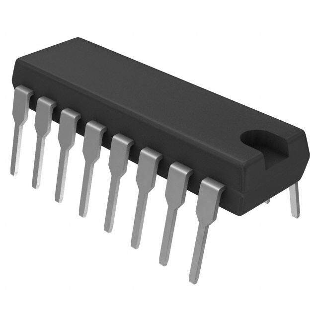
ICGOO电子元器件商城为您提供M40SZ100WMQ6F由STMicroelectronics设计生产,在icgoo商城现货销售,并且可以通过原厂、代理商等渠道进行代购。 M40SZ100WMQ6F价格参考。STMicroelectronicsM40SZ100WMQ6F封装/规格:PMIC - 监控器, 开路漏极或开路集电极 监控器 1 通道 16-SO。您可以下载M40SZ100WMQ6F参考资料、Datasheet数据手册功能说明书,资料中有M40SZ100WMQ6F 详细功能的应用电路图电压和使用方法及教程。
STMicroelectronics(意法半导体)的型号 M40SZ100WMQ6F 属于 PMIC(电源管理集成电路)中的监控器类别。该型号主要应用于需要精确电压监控和系统保护的场景,以下是其典型应用场景:

 1. 嵌入式系统
   - 在嵌入式设备中,M40SZ100WMQ6F 可用于监测主电源或备用电源的电压状态。例如,在工业控制器、物联网设备或智能家居产品中,确保系统的供电稳定性。
   - 提供复位功能,当电压低于设定阈值时,触发系统复位以避免因低电压导致的数据丢失或硬件损坏。

 2. 电池供电设备
   - 在便携式设备(如手持终端、医疗设备或无线传感器)中,该芯片可以实时监控电池电压,防止过放电。
   - 支持在低功耗模式下工作,延长电池寿命。

 3. 通信设备
   - 应用于路由器、交换机或其他网络设备中,监控电源供应是否正常运行。
   - 在多电源架构中,作为辅助监控器确保备用电源的可用性。

 4. 汽车电子
   - 在车载信息娱乐系统、ADAS(高级驾驶辅助系统)或电动车辆中,用于监测关键模块的供电状态。
   - 提供高可靠性保障,适应宽温范围和复杂电磁环境。

 5. 消费类电子产品
   - 在电视、音响、游戏机等消费类产品中,提供电源管理与保护功能。
   - 确保设备在异常情况下能够安全关机或重启。

 核心功能特点:
- 电压监测:支持多种电压输入范围,精准检测电源状态。
- 复位输出:当电压低于预设阈值时,自动触发复位信号。
- 低功耗设计:适合对能效要求较高的应用场合。
- 高集成度:减少外部元件数量,简化电路设计。

综上所述,M40SZ100WMQ6F 广泛适用于需要稳定电源管理和故障保护的各种电子设备,尤其在工业、通信、汽车和消费领域表现出色。
| 参数 | 数值 |
| 产品目录 | 集成电路 (IC) |
| 描述 | IC SUPERVISOR NVRAM 3V 16SOIC |
| 产品分类 | |
| 品牌 | STMicroelectronics |
| 数据手册 | |
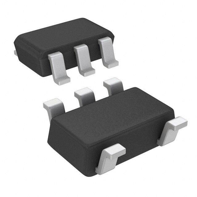
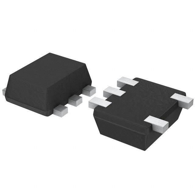
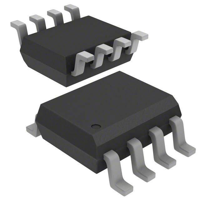
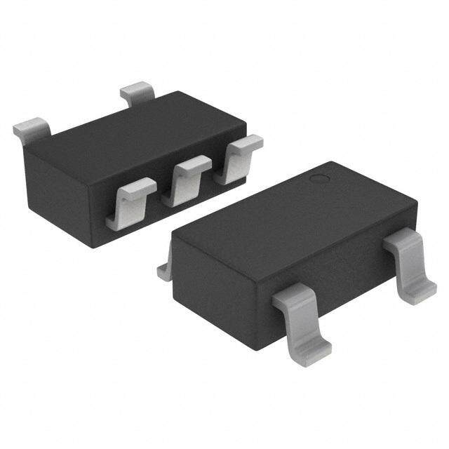
| 产品图片 |
|
| 产品型号 | M40SZ100WMQ6F |
| rohs | 无铅 / 符合限制有害物质指令(RoHS)规范要求 |
| 产品系列 | - |
| 产品目录页面 | |
| 供应商器件封装 | 16-SO |
| 其它名称 | 497-4688-1 |
| 其它有关文件 | http://www.st.com/web/catalog/sense_power/FM1946/SC792/PF63886?referrer=70071840 |
| 包装 | 剪切带 (CT) |
| 受监控电压数 | 1 |
| 复位 | 低有效 |
| 复位超时 | 最小为 40 ms |
| 安装类型 | 表面贴装 |
| 封装/外壳 | 16-SOIC(0.154",3.90mm 宽) |
| 工作温度 | -40°C ~ 85°C |
| 标准包装 | 1 |
| 电压-阈值 | 2.6V |
| 类型 | 简单复位/加电复位 |
| 输出 | 开路漏极或开路集电极 |




- 商务部:美国ITC正式对集成电路等产品启动337调查
- 曝三星4nm工艺存在良率问题 高通将骁龙8 Gen1或转产台积电
- 太阳诱电将投资9.5亿元在常州建新厂生产MLCC 预计2023年完工
- 英特尔发布欧洲新工厂建设计划 深化IDM 2.0 战略
- 台积电先进制程称霸业界 有大客户加持明年业绩稳了
- 达到5530亿美元!SIA预计今年全球半导体销售额将创下新高
- 英特尔拟将自动驾驶子公司Mobileye上市 估值或超500亿美元
- 三星加码芯片和SET,合并消费电子和移动部门,撤换高东真等 CEO
- 三星电子宣布重大人事变动 还合并消费电子和移动部门
- 海关总署:前11个月进口集成电路产品价值2.52万亿元 增长14.8%



PDF Datasheet 数据手册内容提取
M40SZ100W 3 V NVRAM supervisor for LPSRAM Datasheet - production data Description The M40SZ100W NVRAM controller is a self- 16 contained device which converts a standard low- power SRAM into a non-volatile memory. A 1 precision voltage reference and comparator monitors the V input for an out-of-tolerance CC condition. SO16 When an invalid V condition occurs, the CC conditioned chip enable output (E is forced CON) inactive to write protect the stored data in the Features SRAM. During a power failure, the SRAM is switched from the V pin to the external battery Convert low power SRAMs into NVRAMs CC to provide the energy required for data retention. 3 V operating voltage On a subsequent power-up, the SRAM remains Precision power monitoring and power write-protected until a valid power condition switching circuitry returns. Automatic write-protection when V is out-of- CC tolerance Choice of supply voltage and power-fail deselect voltage: – V = 2.7 to 3.6 V; 2.55 V V 2.70 V CC PFD Reset output (RST) for power on reset 1.25 V reference (for PFI/PFO) Less than 15 ns chip enable access propagation delay Battery low pin (BL) RoHS compliant – Lead-free second level interconnect December 2013 DocID007528 Rev 4 1/20 This is information on a product in full production. www.st.com
Contents M40SZ100W Contents 1 Device overview . . . . . . . . . . . . . . . . . . . . . . . . . . . . . . . . . . . . . . . . . . . . 5 2 Operation . . . . . . . . . . . . . . . . . . . . . . . . . . . . . . . . . . . . . . . . . . . . . . . . . . 8 2.1 Data retention lifetime calculation . . . . . . . . . . . . . . . . . . . . . . . . . . . . . . . 8 2.2 Power-on reset output . . . . . . . . . . . . . . . . . . . . . . . . . . . . . . . . . . . . . . . 11 2.3 Reset input (RSTIN) . . . . . . . . . . . . . . . . . . . . . . . . . . . . . . . . . . . . . . . . . 11 2.4 Battery low pin . . . . . . . . . . . . . . . . . . . . . . . . . . . . . . . . . . . . . . . . . . . . . 11 2.5 Power-fail input/output . . . . . . . . . . . . . . . . . . . . . . . . . . . . . . . . . . . . . . . 12 2.6 V noise and negative going transients . . . . . . . . . . . . . . . . . . . . . . . . . 12 CC 3 Maximum ratings . . . . . . . . . . . . . . . . . . . . . . . . . . . . . . . . . . . . . . . . . . . 14 4 DC and AC parameters . . . . . . . . . . . . . . . . . . . . . . . . . . . . . . . . . . . . . . 15 5 Package mechanical data . . . . . . . . . . . . . . . . . . . . . . . . . . . . . . . . . . . . 17 6 Part numbering . . . . . . . . . . . . . . . . . . . . . . . . . . . . . . . . . . . . . . . . . . . . 18 7 Revision history . . . . . . . . . . . . . . . . . . . . . . . . . . . . . . . . . . . . . . . . . . . 19 2/20 DocID007528 Rev 4
M40SZ100W List of tables List of tables Table 1. Signal names . . . . . . . . . . . . . . . . . . . . . . . . . . . . . . . . . . . . . . . . . . . . . . . . . . . . . . . . . . . .5 Table 2. Power-down/up AC characteristics. . . . . . . . . . . . . . . . . . . . . . . . . . . . . . . . . . . . . . . . . . .10 Table 3. Reset AC characteristics. . . . . . . . . . . . . . . . . . . . . . . . . . . . . . . . . . . . . . . . . . . . . . . . . . .11 Table 4. Absolute maximum ratings . . . . . . . . . . . . . . . . . . . . . . . . . . . . . . . . . . . . . . . . . . . . . . . . .14 Table 5. DC and AC measurement conditions . . . . . . . . . . . . . . . . . . . . . . . . . . . . . . . . . . . . . . . . .15 Table 6. Capacitance . . . . . . . . . . . . . . . . . . . . . . . . . . . . . . . . . . . . . . . . . . . . . . . . . . . . . . . . . . . .15 Table 7. DC characteristics. . . . . . . . . . . . . . . . . . . . . . . . . . . . . . . . . . . . . . . . . . . . . . . . . . . . . . . .16 Table 8. SO16 – 16-lead plastic small outline package mechanical data. . . . . . . . . . . . . . . . . . . . .17 Table 9. Ordering information scheme . . . . . . . . . . . . . . . . . . . . . . . . . . . . . . . . . . . . . . . . . . . . . . .18 Table 10. Document revision history. . . . . . . . . . . . . . . . . . . . . . . . . . . . . . . . . . . . . . . . . . . . . . . . . .19 DocID007528 Rev 4 3/20 20
List of figures M40SZ100W List of figures Figure 1. Logic diagram. . . . . . . . . . . . . . . . . . . . . . . . . . . . . . . . . . . . . . . . . . . . . . . . . . . . . . . . . . . .5 Figure 2. Pin connections . . . . . . . . . . . . . . . . . . . . . . . . . . . . . . . . . . . . . . . . . . . . . . . . . . . . . . . . . .6 Figure 3. Block diagram. . . . . . . . . . . . . . . . . . . . . . . . . . . . . . . . . . . . . . . . . . . . . . . . . . . . . . . . . . . .6 Figure 4. Hardware hookup . . . . . . . . . . . . . . . . . . . . . . . . . . . . . . . . . . . . . . . . . . . . . . . . . . . . . . . . .7 Figure 5. Power-down timing. . . . . . . . . . . . . . . . . . . . . . . . . . . . . . . . . . . . . . . . . . . . . . . . . . . . . . . .9 Figure 6. Power-up timing . . . . . . . . . . . . . . . . . . . . . . . . . . . . . . . . . . . . . . . . . . . . . . . . . . . . . . . . .10 Figure 7. RSTIN timing waveform . . . . . . . . . . . . . . . . . . . . . . . . . . . . . . . . . . . . . . . . . . . . . . . . . . .11 Figure 8. Supply voltage protection . . . . . . . . . . . . . . . . . . . . . . . . . . . . . . . . . . . . . . . . . . . . . . . . . .13 Figure 9. AC testing load circuit. . . . . . . . . . . . . . . . . . . . . . . . . . . . . . . . . . . . . . . . . . . . . . . . . . . . .15 Figure 10. AC testing input/output waveforms. . . . . . . . . . . . . . . . . . . . . . . . . . . . . . . . . . . . . . . . . . .15 Figure 11. SO16 – 16-lead plastic small package outline . . . . . . . . . . . . . . . . . . . . . . . . . . . . . . . . . .17 4/20 DocID007528 Rev 4
M40SZ100W Device overview 1 Device overview Figure 1. Logic diagram VCC VBAT VOUT E BL M40SZ100W PFI ECON RSTIN PFO RST VSS AI03933 Table 1. Signal names E Chip enable input E Conditioned chip enable output CON RST Reset output (open drain) RSTIN Reset input BL Battery low output (open drain) V Supply voltage output OUT V Supply voltage CC V Backup supply voltage BAT PFI Power fail input PFO Power fail output V Ground SS NC Not connected internally DocID007528 Rev 4 5/20 20
Device overview M40SZ100W Figure 2. Pin connections NC 1 16 VCC NC 2 15 NC RST 3 14 VOUT NC 4 M40SZ100W13 NC RSTIN 5 12 PFI PFO 6 11 BL VBAT 7 10 E VSS 8 9 ECON AI03935 Figure 3. Block diagram VCC VOUT VBAT (1) VBL= 2.5V COMPARE BL VSO = 2.5V COMPARE VPFD= 2.65V COMPARE POR (1) RSTIN RST E ECON PFI COMPARE PFO 1.25V AI04766 1. Open drain output 6/20 DocID007528 Rev 4
M40SZ100W Device overview Figure 4. Hardware hookup 3.0V, 3.3V Regulator Unregulated Voltage VIN VCC VCC VOUT VCC 0.1μF M40SZ100W 1Mb or 4Mb 0.1μF LPSRAM E E From Microprocessor RSTIN ECON R1 PFI PFO To Microprocessor NMI R2 VSS RST To Microprocessor Reset VBAT BL To Battery Monitor Circuit AI04767 DocID007528 Rev 4 7/20 20
Operation M40SZ100W 2 Operation The M40SZ100W, as shown in Figure 4 on page 7, can control one (two, if placed in parallel) standard low-power SRAM. This SRAM must be configured to have the chip enable input disable all other input signals. Most slow, low-power SRAMs are configured like this, however many fast SRAMs are not. During normal operating conditions, the conditioned chip enable (E ) output pin follows the chip enable (E) input pin with timing shown in CON Table 2 on page 10. An internal switch connects V to V . This switch has a voltage CC OUT drop of less than 0.3 V (I ). OUT1 When V degrades during a power failure, E is forced inactive independent of E. In CC CON this situation, the SRAM is unconditionally write protected as V falls below an out-of- CC tolerance threshold (V ). For the M40SZ100W the power fail detection value associated PFD with V is shown in Table 7 on page 16. PFD If chip enable access is in progress during a power fail detection, that memory cycle continues to completion before the memory is write protected. If the memory cycle is not terminated within time t , E is unconditionally driven high, write protecting the SRAM. WPT CON A power failure during a WRITE cycle may corrupt data at the currently addressed location, but does not jeopardize the rest of the SRAM's contents. At voltages below V (min), the PFD user can be assured the memory will be write protected within the Write Protect Time (t ) WPT provided the V fall time does not exceed t (see Table 2 on page 10). CC F As V continues to degrade, the internal switch disconnects V and connects the internal CC CC battery to V . This occurs at the switchover voltage (V ). Below the V , the battery OUT SO SO provides a voltage V to the SRAM and can supply current I (see Table 7 on OHB OUT2 page 16). When V rises above V , V is switched back to the supply voltage. Output E is CC SO OUT CON held inactive for t (120 ms maximum) after the power supply has reached V , CER PFD independent of the E input, to allow for processor stabilization (see Figure 6 on page 10). 2.1 Data retention lifetime calculation Most low power SRAMs on the market today can be used with the M40SZ100W NVRAM controller. There are, however some criteria which should be used in making the final choice of which SRAM to use. The SRAM must be designed in a way where the chip enable input disables all other inputs to the SRAM. This allows inputs to the M40SZ100W and SRAMs to be “Don't care” once V falls below V (min) (see Figure 5 on page 9). The SRAM should CC PFD also guarantee data retention down to V = 2.0 V. The chip enable access time must be CC sufficient to meet the system needs with the chip enable propagation delays included. If data retention lifetime is a critical parameter for the system, it is important to review the data retention current specifications for the particular SRAMs being evaluated. Most SRAMs specify a data retention current at 3.0 V. Manufacturers generally specify a typical condition for room temperature along with a worst case condition (generally at elevated temperatures). The system level requirements will determine the choice of which value to use. The data retention current value of the SRAMs can then be added to the I value of CCDR the M40SZ100W to determine the total current requirements for data retention. Caution: Take care to avoid inadvertent discharge through V and E after battery has been OUT CON attached. 8/20 DocID007528 Rev 4
M40SZ100W Operation For a further more detailed review of lifetime calculations, please see application note AN1012. Figure 5. Power-down timing VCC VPFD (max) VPFD VPFD (min) VSO tF tFB E tWPT VOHB ECON RST PFO VALID AI03936 DocID007528 Rev 4 9/20 20
Operation M40SZ100W Figure 6. Power-up timing VCC VPFD (max) VPFD VPFD (min) VSO tR tRB tCER E tEPD tEPD VOHB ECON tREC RST PFO VALID AI03937 Table 2. Power-down/up AC characteristics Symbol Parameter(1) Min Max Unit t (2) V (max) to V (min) V fall time 300 μs F PFD PFD CC t (3) V (min) to V V fall time 10 μs FB PFD SS CC t PFI to PFO propagation delay 15 25 μs PFD t V (min) to V (max) V rise time 10 μs R PFD PFD CC t Chip enable propagation delay (low or high) 15 ns EPD t V to V (min) V rise time 1 μs RB SS PFD CC t Chip enable recovery 40 120 ms CER t V (max) to RST high 40 200 ms REC PFD t Write protect time 40 200 μs WPT 1. Valid for ambient operating temperature: T = –40 to 85 °C; V = 2.7 to 3.6 V (except where noted). A CC 2. V (max) to V (min) fall time of less than t may result in deselection/write protection not occurring until 200 μs after PFD PFD F V passes V (min). CC PFD 3. V (min) to V fall time of less than t may cause corruption of RAM data. PFD SS FB 10/20 DocID007528 Rev 4
M40SZ100W Operation 2.2 Power-on reset output All microprocessors have a reset input which forces them to a known state when starting. The M40SZ100W has a reset output (RST) pin which is guaranteed to be low by V (see PFD Table 7 on page 16). This signal is an open drain configuration. An appropriate pull-up resistor to V should be chosen to control the rise time. This signal will be valid for all CC voltage conditions, even when V equals V (with valid battery voltage). CC SS Once V exceeds the power failure detect voltage V , an internal timer keeps RST low CC PFD for t to allow the power supply to stabilize. REC 2.3 Reset input (RSTIN) The M40SZ100W provides one independent input which can generate an output reset. The duration and function of this reset is identical to a reset generated by a power cycle. Table 3 and Figure 7 illustrate the AC reset characteristics of this function. Pulses shorter than t RLRH will not generate a reset condition. RSTIN is internally pulled up to V through a 100 k CC resistor. Figure 7. RSTIN timing waveform RSTIN tRLRH RST (1) tR1HRH AI04768 1. With pull-up resistor Table 3. Reset AC characteristics Symbol Parameter(1) Min Max Unit t (2) RSTIN low to RSTIN high 200 ns RLRH t (3) RSTIN high to RST high 40 200 ms R1HRH 1. Valid for ambient operating temperature: T = –40 to 85 °C; V = 2.7 to 3.6 V (except where noted). A CC 2. Pulse width less than 50 ns will result in no RESET (for noise immunity). 3. C = 50 pF (see Figure 9 on page 15). L 2.4 Battery low pin The M40SZ100W automatically performs battery voltage monitoring upon power-up, and at factory-programmed time intervals of at least 24 hours. The Battery Low (BL) pin will be asserted if the battery voltage is found to be less than approximately 2.5 V. The BL pin will remain asserted until completion of battery replacement and subsequent battery low monitoring tests, either during the next power-up sequence or the next scheduled 24-hour interval. DocID007528 Rev 4 11/20 20
Operation M40SZ100W If a battery low is generated during a power-up sequence, this indicates that the battery is below 2.5 V and may not be able to maintain data integrity in the SRAM. Data should be considered suspect, and verified as correct. A fresh battery should be installed. If a battery low indication is generated during the 24-hour interval check, this indicates that the battery is near end of life. However, data is not compromised due to the fact that a nominal V is supplied. In order to insure data integrity during subsequent periods of CC battery back-up mode, the battery should be replaced. The M40SZ100W only monitors the battery when a nominal V is applied to the device. CC Thus applications which require extensive durations in the battery backup mode should be powered-up periodically (at least once every few months) in order for this technique to be beneficial. Additionally, if a battery low is indicated, data integrity should be verified upon power-up via a checksum or other technique. The BL pin is an open drain output and an appropriate pull-up resistor to V should be chosen to control the rise time. CC 2.5 Power-fail input/output The power-fail input (PFI) is compared to an internal reference voltage (independent from the V comparator). If PFI is less than the power-fail threshold (V ), the power-fail PFD PFI output (PFO) will go low. This function is intended for use as an undervoltage detector to signal a failing power supply. Typically PFI is connected through an external voltage divider (see Figure 4 on page 7) to either the unregulated DC input (if it is available) or the regulated output of the V regulator. The voltage divider can be set up such that the CC voltage at PFI falls below V several milliseconds before the regulated V input to the PFI CC M40SZ100W or the microprocessor drops below the minimum operating voltage. During battery backup, the power-fail comparator turns off and PFO goes (or remains) low. This occurs after V drops below V (min). When power returns, PFO is forced high, CC PFD irrespective of V for the write protect time (t ), which is the time from V (max) until PFI REC PFD the inputs are recognized. At the end of this time, the power-fail comparator is enabled and PFO follows PFI. If the comparator is unused, PFI should be connected to V and PFO left SS unconnected. 2.6 V noise and negative going transients CC I transients, including those produced by output switching, can produce voltage CC fluctuations, resulting in spikes on the V bus. These transients can be reduced if CC capacitors are used to store energy which stabilizes the V bus. The energy stored in the CC bypass capacitors will be released as low going spikes are generated or energy will be absorbed when overshoots occur. A ceramic bypass capacitor value of 0.1 μF (as shown in Figure 8 on page 13) is recommended in order to provide the needed filtering. In addition to transients that are caused by normal SRAM operation, power cycling can generate negative voltage spikes on V that drive it to values below V by as much as CC SS one volt. These negative spikes can cause data corruption in the SRAM while in battery backup mode. To protect from these voltage spikes, STMicroelectronics recommends connecting a Schottky diode from V to V (cathode connected to V , anode to V ). CC SS CC SS Schottky diode 1N5817 is recommended for through hole and MBRS120T3 is recommended for surface mount. 12/20 DocID007528 Rev 4
M40SZ100W Operation Figure 8. Supply voltage protection VCC VCC 0.1µF DEVICE VSS AI00622 DocID007528 Rev 4 13/20 20
Maximum ratings M40SZ100W 3 Maximum ratings Stressing the device above the rating listed in the absolute maximum ratings table may cause permanent damage to the device. These are stress ratings only and operation of the device at these or any other conditions above those indicated in the operating sections of this specification is not implied. Exposure to absolute maximum rating conditions for extended periods may affect device reliability. Table 4. Absolute maximum ratings Symbol Parameter Value Unit T Storage temperature (V off) –55 to 125 °C STG CC T (1) Lead solder temperature for 10 seconds 260 °C SLD V Input or output voltages –0.3 to V +0.3 V IO CC V Supply voltage –0.3 to 4.6 V CC I Output current 20 mA O P Power dissipation 1 W D 1. For SO package, Lead-free (Pb-free) lead finish: reflow at peak temperature of 260 °C (the time above 255 °C must not exceed 30 seconds). Caution: Negative undershoots below –0.3 V are not allowed on any pin while in the battery backup mode. 14/20 DocID007528 Rev 4
M40SZ100W DC and AC parameters 4 DC and AC parameters This section summarizes the operating and measurement conditions, as well as the DC and AC characteristics of the device. The parameters in the following DC and AC characteristic tables are derived from tests performed under the measurement conditions listed in Table 5: DC and AC measurement conditions. Designers should check that the operating conditions in their projects match the measurement conditions when using the quoted parameters. Table 5. DC and AC measurement conditions Parameter Value V supply voltage 2.7 to 3.6 V CC Ambient operating temperature –40 to 85 °C Load capacitance (C ) 50 pF L Input rise and fall times 5 ns Input pulse voltages 0.2 to 0.8V CC Input and output timing ref. voltages 0.3 to 0.7V CC Figure 9. AC testing load circuit 333 DEVICE UNDER TEST CL = 50pF 1.73V CL includes JIG capacitance AI02393 Figure 10. AC testing input/output waveforms 0.8VCC 0.7VCC 0.3VCC 0.2VCC AI02568 Table 6. Capacitance Symbol Parameter(1)(2) Min Max Unit C Input capacitance - 7 pF IN C (3) Output capacitance - 10 pF OUT 1. Sampled only, not 100% tested. 2. At 25 °C, f = 1 MHz. 3. Outputs deselected. DocID007528 Rev 4 15/20 20
DC and AC parameters M40SZ100W Table 7. DC characteristics Sym Parameter Test condition(1) Min Typ Max Unit I Supply current Outputs open 0.5 mA CC I Data retention mode current(2) 50 200 nA CCDR Input leakage current 0 V V V ±1 μA I (3) IN CC LI Input leakage current (PFI) –25 2 25 nA I (4) Output leakage current 0 V V V ±1 μA LO OUT CC I (5) V current (active) V > V – 0.3 100 mA OUT1 OUT OUT CC I V current (battery backup) V > V – 0.3 100 μA OUT2 OUT OUT BAT V Battery voltage 2.5 3.0 3.5(6) V BAT V Input high voltage 0.7V V + 0.3 V IH CC CC V Input low voltage –0.3 0.3V V IL CC V Output high voltage(6) I = –1.0 mA 2.4 V OH OH V V battery backup(7) I = –1.0 μA 2.5 2.9 3.5 V OHB OH OUT2 Output low voltage I = 3.0 mA 0.4 V OL VOL Output low voltage (open I = 10 mA 0.4 V drain)(8) OL V Power-fail deselect voltage 2.55 2.60 2.70 V PFD PFI input threshold V = 3 V 1.225 1.250 1.275 V CC V PFI PFI hysteresis PFI rising 20 70 mV Battery backup switchover V 2.5 V SO voltage 1. Valid for ambient operating temperature: T = –40 to 85 °C; V = 2.7 to 3.6 V (except where noted). A CC 2. Measured with V and E open. OUT CON 3. RSTIN internally pulled-up to V through 100 k resistor. CC 4. Outputs deselected. 5. External SRAM must match SUPERVISOR chip V specification. CC 6. For PFO pin (CMOS). 7. Chip enable output (E ) can only sustain CMOS leakage currents in the battery backup mode. Higher CON leakage currents will reduce battery life. 8. For RST & BL pins (open drain). 16/20 DocID007528 Rev 4
M40SZ100W Package mechanical data 5 Package mechanical data In order to meet environmental requirements, ST offers these devices in different grades of ECOPACK® packages, depending on their level of environmental compliance. ECOPACK® specifications, grade definitions and product status are available at: www.st.com. ECOPACK® is an ST trademark. Figure 11. SO16 – 16-lead plastic small package outline A2 A C B CP e D N E H 1 A1 α L SO-b Note: Drawing is not to scale. Table 8. SO16 – 16-lead plastic small outline package mechanical data mm inches Symbol Typ. Min. Max. Typ. Min. Max. A 1.75 0.069 A1 0.10 0.25 0.004 0.010 A2 1.60 0.063 B 0.35 0.46 0.014 0.018 C 0.19 0.25 0.007 0.010 D 9.80 10.00 0.386 0.394 E 3.80 4.00 0.150 0.158 e 1.27 – – 0.050 – – H 5.80 6.20 0.228 0.244 L 0.40 1.27 0.016 0.050 a 0° 8° 0° 8° N 16 16 CP 0.10 0.004 DocID007528 Rev 4 17/20 20
Part numbering M40SZ100W 6 Part numbering Table 9. Ordering information scheme Example: M40SZ 100W MQ 6 F Device type M40SZ Supply voltage and write protect voltage 100W = V = 2.7 to 3.6 V; V = 2.6 to 2.7 V CC PFD Package MQ = SO16 Temperature range 6 = –40 to 85 °C Shipping method F = Lead-free ECOPACK® package, tape & reel For a list of available options (e.g., speed, package) or for further information on any aspect of this device, please contact the ST sales office nearest to you. 18/20 DocID007528 Rev 4
M40SZ100W Revision history 7 Revision history Table 10. Document revision history Date Revision Changes Dec-2001 1.0 First issue 13-May-2002 1.1 Modify reflow time and temperature footnote (Table 4) 01-Aug-2002 1.2 Add marketing status (cover page; Table 9) Remove reference to M68xxx (obsolete) part (Figure 4); update 15-Sep-2003 1.3 disclaimer Reformatted document; added lead-free second level interconnect 20-Nov-2007 2 information to cover page and Section 5: Package mechanical data; updated Table 4 and 9. Updated cover page, Section 3, Table 9, ECOPACK® text in 25-Oct-2010 3 Section 5; reformatted document; minor textual changes. Removed SNAPHAT and SOH28 package option as well as 5 V part 16-Dec-2013 4 (M40SZ100Y) from datasheet Removed shipping option in tubes from Table 9 DocID007528 Rev 4 19/20 20
M40SZ100W Please Read Carefully: Information in this document is provided solely in connection with ST products. STMicroelectronics NV and its subsidiaries (“ST”) reserve the right to make changes, corrections, modifications or improvements, to this document, and the products and services described herein at any time, without notice. All ST products are sold pursuant to ST’s terms and conditions of sale. Purchasers are solely responsible for the choice, selection and use of the ST products and services described herein, and ST assumes no liability whatsoever relating to the choice, selection or use of the ST products and services described herein. No license, express or implied, by estoppel or otherwise, to any intellectual property rights is granted under this document. If any part of this document refers to any third party products or services it shall not be deemed a license grant by ST for the use of such third party products or services, or any intellectual property contained therein or considered as a warranty covering the use in any manner whatsoever of such third party products or services or any intellectual property contained therein. UNLESS OTHERWISE SET FORTH IN ST’S TERMS AND CONDITIONS OF SALE ST DISCLAIMS ANY EXPRESS OR IMPLIED WARRANTY WITH RESPECT TO THE USE AND/OR SALE OF ST PRODUCTS INCLUDING WITHOUT LIMITATION IMPLIED WARRANTIES OF MERCHANTABILITY, FITNESS FOR A PARTICULAR PURPOSE (AND THEIR EQUIVALENTS UNDER THE LAWS OF ANY JURISDICTION), OR INFRINGEMENT OF ANY PATENT, COPYRIGHT OR OTHER INTELLECTUAL PROPERTY RIGHT. ST PRODUCTS ARE NOT DESIGNED OR AUTHORIZED FOR USE IN: (A) SAFETY CRITICAL APPLICATIONS SUCH AS LIFE SUPPORTING, ACTIVE IMPLANTED DEVICES OR SYSTEMS WITH PRODUCT FUNCTIONAL SAFETY REQUIREMENTS; (B) AERONAUTIC APPLICATIONS; (C) AUTOMOTIVE APPLICATIONS OR ENVIRONMENTS, AND/OR (D) AEROSPACE APPLICATIONS OR ENVIRONMENTS. WHERE ST PRODUCTS ARE NOT DESIGNED FOR SUCH USE, THE PURCHASER SHALL USE PRODUCTS AT PURCHASER’S SOLE RISK, EVEN IF ST HAS BEEN INFORMED IN WRITING OF SUCH USAGE, UNLESS A PRODUCT IS EXPRESSLY DESIGNATED BY ST AS BEING INTENDED FOR “AUTOMOTIVE, AUTOMOTIVE SAFETY OR MEDICAL” INDUSTRY DOMAINS ACCORDING TO ST PRODUCT DESIGN SPECIFICATIONS. PRODUCTS FORMALLY ESCC, QML OR JAN QUALIFIED ARE DEEMED SUITABLE FOR USE IN AEROSPACE BY THE CORRESPONDING GOVERNMENTAL AGENCY. Resale of ST products with provisions different from the statements and/or technical features set forth in this document shall immediately void any warranty granted by ST for the ST product or service described herein and shall not create or extend in any manner whatsoever, any liability of ST. ST and the ST logo are trademarks or registered trademarks of ST in various countries. Information in this document supersedes and replaces all information previously supplied. The ST logo is a registered trademark of STMicroelectronics. All other names are the property of their respective owners. © 2013 STMicroelectronics - All rights reserved STMicroelectronics group of companies Australia - Belgium - Brazil - Canada - China - Czech Republic - Finland - France - Germany - Hong Kong - India - Israel - Italy - Japan - Malaysia - Malta - Morocco - Philippines - Singapore - Spain - Sweden - Switzerland - United Kingdom - United States of America www.st.com 20/20 DocID007528 Rev 4
Mouser Electronics Authorized Distributor Click to View Pricing, Inventory, Delivery & Lifecycle Information: S TMicroelectronics: M40SZ100WMQ6E M40SZ100WMQ6F

 Datasheet下载