
 Datasheet下载
- 型号: LTM4630EY#PBF
- 制造商: LINEAR TECHNOLOGY
- 库位|库存: xxxx|xxxx
- 要求:
| 数量阶梯 | 香港交货 | 国内含税 |
| +xxxx | $xxxx | ¥xxxx |
查看当月历史价格
查看今年历史价格
LTM4630EY#PBF产品简介:
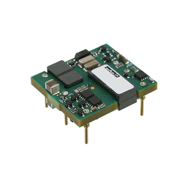
ICGOO电子元器件商城为您提供LTM4630EY#PBF由LINEAR TECHNOLOGY设计生产,在icgoo商城现货销售,并且可以通过原厂、代理商等渠道进行代购。 LTM4630EY#PBF价格参考。LINEAR TECHNOLOGYLTM4630EY#PBF封装/规格:直流转换器, 非隔离 PoL 模块 DC/DC 转换器 2 输出 0.6 ~ 1.8 V 0.6 ~ 1.8 V 18A,18A 4.5V - 15V 输入。您可以下载LTM4630EY#PBF参考资料、Datasheet数据手册功能说明书,资料中有LTM4630EY#PBF 详细功能的应用电路图电压和使用方法及教程。
LTM4630EY#PBF 是由 Linear Technology(现为 Analog Devices 旗下品牌)生产的一款高效率、低噪声的直流-直流转换器模块,属于 µModule 系列。该器件集成了开关控制器、功率 FET、电感器和其他支持组件,能够提供高达 12A 的连续输出电流,并支持 0.8V 至 5.5V 的可调输出电压范围。其输入电压范围为 2.375V 至 5.5V,适用于多种电源场景。

以下是 LTM4630EY#PBF 的主要应用场景:

 1. 高性能计算与服务器
   - 在数据中心和服务器应用中,LTM4630 提供稳定的电源供应,支持多核处理器、FPGA 和 ASIC 的供电需求。
   - 其紧凑的设计和高效率特性使其非常适合空间受限的主板设计。

 2. 通信设备
   - 应用于路由器、交换机和基站等通信设备中,为数字信号处理器 (DSP) 和网络接口芯片提供高效电源。
   - 支持低噪声输出,确保通信系统的信号完整性。

 3. 工业自动化
   - 在工业控制和自动化系统中,为微控制器、传感器接口和数据采集模块供电。
   - 能够承受工业环境中的宽温度范围和振动条件。

 4. 医疗设备
   - 用于便携式医疗设备(如监护仪、超声波设备)中,提供稳定且低噪声的电源。
   - 其小尺寸和高集成度有助于减小设备体积,同时保持高可靠性。

 5. 汽车电子
   - 在车载信息娱乐系统、ADAS(高级驾驶辅助系统)和仪表盘模块中,为 MCU 和图像处理单元供电。
   - 支持汽车级工作温度范围(-40°C 至 +125°C),满足严苛的汽车环境要求。

 6. 消费类电子产品
   - 为笔记本电脑、平板电脑和高端智能手机中的核心处理器供电。
   - 其高效的电源转换能力有助于延长电池续航时间。

 特点总结:
- 高集成度:减少了外部元件数量,简化了电路设计。
- 高效率:在满载条件下效率可达 90% 以上。
- 小型化:采用 BGA 封装,节省 PCB 空间。
- 低电磁干扰 (EMI):优化的布局设计降低了对其他敏感电路的影响。

总之,LTM4630EY#PBF 以其高效率、高可靠性和紧凑设计,广泛应用于需要高性能电源管理的各类场景。
| 参数 | 数值 |
| 产品目录 | |
| 描述 | DC/DC CONVERTER 2X0.6-1.8V 65W |
| 产品分类 | DC DC Converters |
| 品牌 | Linear Technology |
| 数据手册 | |
| 产品图片 |
|
| 产品型号 | LTM4630EY#PBF |
| rohs | 无铅 / 符合限制有害物质指令(RoHS)规范要求 |
| 产品系列 | µModule® |
| 功率(W)-制造系列 | 65W |
| 功率(W)-最大值 | 65W |
| 包装 | 管件 |
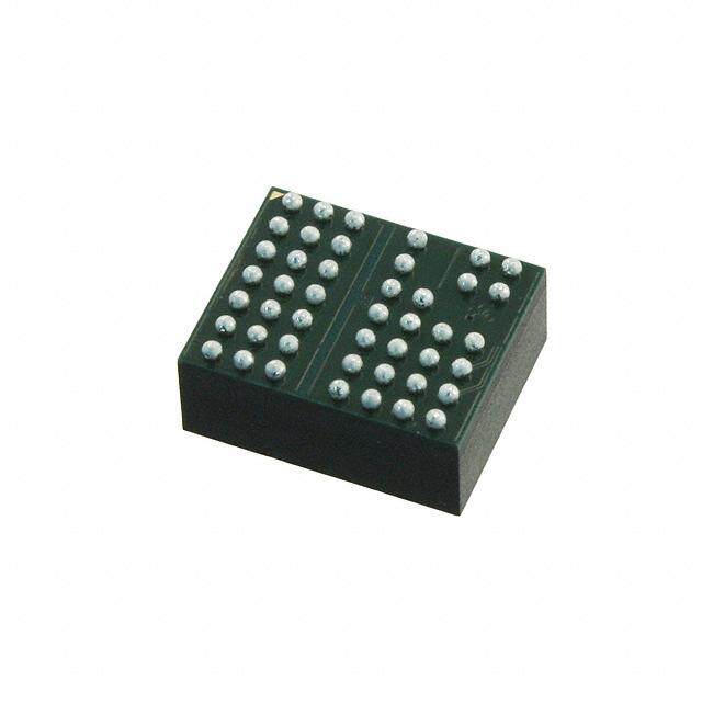
| 大小/尺寸 | 0.63" 长 x 0.63" 宽 x 0.17" 高 (16.0mm x 16.0mm x 4.4mm) |
| 安装类型 | 表面贴装 |
| 封装/外壳 | 144-BGA |
| 工作温度 | -40°C ~ 125°C |
| 效率 | - |
| 标准包装 | 90 |
| 特性 | OCP,OVP |
| 电压-输入(最大值) | 15V |
| 电压-输入(最小值) | 4.5V |
| 电压-输出1 | 0.6 ~ 1.8 V |
| 电压-输出2 | 0.6 ~ 1.8 V |
| 电压-输出3 | - |
| 电压-隔离 | - |
| 电流-输出(最大值) | 18A、 18A |
| 类型 | 非隔离 PoL 模块 |
| 输出数 | 2 |
| 配用 | /product-detail/zh/DC1892A/DC1892A-ND/4866618 |


- 商务部:美国ITC正式对集成电路等产品启动337调查
- 曝三星4nm工艺存在良率问题 高通将骁龙8 Gen1或转产台积电
- 太阳诱电将投资9.5亿元在常州建新厂生产MLCC 预计2023年完工
- 英特尔发布欧洲新工厂建设计划 深化IDM 2.0 战略
- 台积电先进制程称霸业界 有大客户加持明年业绩稳了
- 达到5530亿美元!SIA预计今年全球半导体销售额将创下新高
- 英特尔拟将自动驾驶子公司Mobileye上市 估值或超500亿美元
- 三星加码芯片和SET,合并消费电子和移动部门,撤换高东真等 CEO
- 三星电子宣布重大人事变动 还合并消费电子和移动部门
- 海关总署:前11个月进口集成电路产品价值2.52万亿元 增长14.8%


PDF Datasheet 数据手册内容提取
LTM4630 Dual 18A or Single 36A DC/DC µModule Regulator FEATURES DESCRIPTION n Dual 18A or Single 36A Output The LTM®4630 is a dual 18A or single 36A output switching n Wide Input Voltage Range: 4.5V to 15V mode step-down DC/DC µModule® (micromodule) regula- n Output Voltage Range: 0.6V to 1.8V tor. Included in the package are the switching controllers, n ±1.5% Maximum Total DC Output Error Over Line, power FETs, inductors, and all supporting components. Load and Temperature Operating from an input voltage range of 4.5V to 15V, the n Differential Remote Sense Amplifier LTM4630 supports two outputs each with an output voltage n Current Mode Control/Fast Transient Response range of 0.6V to 1.8V, each set by a single external resistor. n Adjustable Switching Frequency Its high efficiency design delivers up to 18A continuous n Overcurrent Foldback Protection current for each output. Only a few input and output ca- n Multiphase Parallel Current Sharing with Multiple pacitors are needed. The LTM4630 is pin compatible with LTM4630s Up to 144A the LTM4620 and LTM4620A (dual 13A, single 26A) and n Frequency Synchronization the LTM4628 (dual 8A, single 16A). n Internal Temperature Monitor The device supports frequency synchronization, multi- n Pin Compatible with the LTM4620 and LTM4620A (Dual phase operation, Burst Mode operation and output voltage 13A, Single 26A) and LTM4628 (Dual 8A, Single 16A) tracking for supply rail sequencing and has an onboard n Selectable Burst Mode® Operation temperature diode for device temperature monitoring. High n Soft-Start/Voltage Tracking switching frequency and a current mode architecture enable n Output Overvoltage Protection a very fast transient response to line and load changes n 16mm × 16mm × 4.41mm LGA and 16mm × 16mm × without sacrificing stability. 5.01mm BGA Packages Fault protection features include overvoltage and APPLICATIONS overcurrent protection. The LTM4630 is offered in 16mm × 16mm × 4.41mm LGA and 16mm × 16mm × 5.01mm n Telecom and Networking Equipment BGA packages. The LTM4630 is ROHS compliant. n Storage and ATCA Cards n Industrial Equipment L, LT, LTC, LTM, Linear Technology, the Linear logo, µModule, Burst Mode and PolyPhase are registered trademarks of Linear Technology Corporation. All other trademarks are the property of their respective owners. Protected by U.S. Patents, including 5481178, 5705919, 5929620, 6100678, 6144194, 6177787, 6304066 and 6580258. Other patents pending. TYPICAL APPLICATION 36A, 1.2V Output DC/DC µModule Regulator INTVCC 1.2V Efficiency vs I OUT OUT 4.7µF 10k PGOOD 95 4.5V TO 1V5IVN 22µF MVOINDE_PLLIN CLKOUT INTVCC EXTVCC PGOVOOUDT11 + 90 VIN = 5V 10k 25V 120k TEMP VOUTS1 100µF 470µF ×4 RUN1 DIFFOUT 6.3V 6.3V %) 85 VIN = 12V RUN2 SW1 Y ( C 5.1V TTRRAACCKK12 LTM4630 VVFFBB21 60.4k EFFICIEN 8705 0.1µF fSET COMP1 PHASMD COMP2 70 VOUTS2 VOUT 121k VOSUWT22 100µF+ 470µF 13.62AV 650 2 4 6 8 10 12 14 16 18 PGOOD2 6.3V 6.3V OUTPUT CURRENT (A) SGND GND DIFFP DIFFN PGOOD 4630 TA01b 4630 TA01a 4630fa 1 For more information www.linear.com/LTM4630
LTM4630 ABSOLUTE MAXIMUM RATINGS (Note 1) V (Note 8) ...............................................–0.3V to 16V DIFFP, DIFFN ..........................................–0.3V to INTV IN CC V , V ...................................................–1V to 16V COMP1, COMP2, V , V (Note 6) ........–0.3V to 2.7V SW1 SW2 FB1 FB2 PGOOD1, PGOOD2, RUN1, RUN2, INTV Peak Output Current ................................100mA CC INTV , EXTV ...........................................–0.3V to 6V Internal Operating Temperature Range CC CC MODE_PLLIN, f , TRACK1, TRACK2, (Note 2) .............................................–40°C to 125°C SET DIFFOUT, PHASMD ................................–0.3V to INTV Storage Temperature Range ...................–55°C to 125°C CC V , V , V , V (Note 6) ........–0.3V to 6V Peak Package Body Temperature ..........................245°C OUT1 OUT2 OUTS1 OUTS2 PIN CONFIGURATION TOP VIEW TOP VIEW TEMP EXTVCC TEMP EXTVCC M M L VIN L K K J J CLKSOWUT1 H SINWTV2CC CLKOUT H SINWTV2CC MODPEH_APSLMLIDN GF GND RUNC1OMPS1GCNODMP2 PPRDDGGUIIFFOONFFPOOO2UDDT12 MODPEH_APSLSLMWIND1 GF GND RUNC1OMPS1GCNODMP2 PPRDGGUIFOONFOOO2UDDT12 TRAVCFKB11 DCE SfGSENTDSVGFNB2DTVROAUCTKS22 GND DIFFN TRAVCFKB11 DE SfGSENTDSVGFNB2DTVROAUCTKS22 GND DDIIFFFFPN VOUTS1 VOUTS1 C B VOUT1 GND VOUT2 B GND VOUT2 A A 1 2 3 4 5 6 7 8 9 10 11 12 1 2 3 4 5 6 7 8 9 10 11 12 LGA PACKAGE BGA PACKAGE 144-LEAD (16mm × 16mm × 4.41mm) 144-LEAD (16mm × 16mm × 4.41mm) TJMAX = 125°C, ΘJA = 7°C/W, ΘJCbottom = 1.5°C/W, ΘJCtop = 3.7°C/W, ΘJB + ΘJBA ≅ 7°C/W TJMAX = 125°C, ΘJA = 7°C/ΘW ,V ΘALJCUbEoStto DmE =F I1N.E5D°C P/WER, Θ JJECStoDp 5=1 3-1.72°C/W, ΘJB + ΘJBA ≅ 7°C/W Θ VALUES DEFINED PER JESD 51-12 WEIGHT = 3.2g WEIGHT = 3.2g ORDER INFORMATION PART MARKING* PACKAGE MSL TEMPERATURE RANGE PART NUMBER PAD OR BALL FINISH DEVICE FINISH CODE TYPE RATING (Note 2) LTM4630EV#PBF Au (RoHS) LTM4630V e4 LGA 3 –40°C to 125°C LTM4630IV#PBF Au (RoHS) LTM4630V e4 LGA 3 –40°C to 125°C LTM4630EY#PBF SAC305 (RoHS) LTM4630Y e1 BGA 3 –40°C to 125°C LTM4630IY#PBF SAC305 (RoHS) LTM4630Y e1 BGA 3 –40°C to 125°C LTM4630IY SnPb (63/37) LTM4630Y e0 BGA 3 –40°C to 125°C Consult Marketing for parts specified with wider operating temperature • Recommended LGA and BGA PCB Assembly and Manufacturing ranges. *Device temperature grade is indicated by a label on the shipping Procedures: container. Pad or ball finish code is per IPC/JEDEC J-STD-609. www.linear.com/umodule/pcbassembly • Terminal Finish Part Marking: • LGA and BGA Package and Tray Drawings: www.linear.com/leadfree www.linear.com/packaging 4630fa 2 For more information www.linear.com/LTM4630
LTM4630 ELECTRICAL CHARACTERISTICS The l denotes the specifications which apply over the specified internal operating temperature range. Specified as each individual output channel. T = 25°C (Note 2), V = 12V and V , V at 5V A IN RUN1 RUN2 unless otherwise noted. Per the typical application in Figure 23. SYMBOL PARAMETER CONDITIONS MIN TYP MAX UNITS V Input DC Voltage l 4.5 15 V IN V Output Voltage l 0.6 1.8 V OUT VOUT1(DC), Output Voltage, Total Variation with CIN = 22µF × 3, COUT = 100µF × 1 Ceramic, l 1.477 1.5 1.523 V VOUT2(DC) Line and Load 470µF POSCAP V = 12V, V = 1.5V, I = 0A to 18A IN OUT OUT Input Specifications V , V RUN Pin On/Off Threshold RUN Rising 1.1 1.25 1.40 V RUN1 RUN2 V , V RUN Pin On Hysteresis 150 mV RUN1HYS RUN2HYS I Input Inrush Current at Start-Up I = 0A, C = 22µF ×3, C = 0.01µF, 1 A INRUSH(VIN) OUT IN SS C = 100µF ×3, V = 1.5V, V = 1.5V, OUT OUT1 OUT2 V = 12V IN I Input Supply Bias Current V = 12V, V = 1.5V, Burst Mode Operation 3 mA Q(VIN) IN OUT V = 12V, V = 1.5V, Pulse-Skipping Mode 15 mA IN OUT V = 12V, V = 1.5V, Switching Continuous 65 mA IN OUT Shutdown, RUN = 0, V = 12V 50 µA IN I Input Supply Current V = 5V, V = 1.5V, I = 18A 6 A S(VIN) IN OUT OUT V = 12V, V = 1.5V, I = 18A 2.6 A IN OUT OUT Output Specifications I , I Output Continuous Current Range V = 12V, V = 1.5V (Note 7) 0 18 A OUT1(DC) OUT2(DC) IN OUT ΔV /V Line Regulation Accuracy V = 1.5V, V from 4.5V to 15V l 0.01 0.025 %/V OUT1(LINE) OUT1 OUT IN ΔV /V I = 0A for Each Output, OUT2(LINE) OUT2 OUT ΔV /V Load Regulation Accuracy For Each Output, V = 1.5V, 0A to 18A l 0.5 0.75 % OUT1 OUT1 OUT ΔV /V V = 12V (Note 7) OUT2 OUT2 IN V , V Output Ripple Voltage For Each Output, I = 0A, C = 100µF ×3/ 15 mV OUT1(AC) OUT2(AC) OUT OUT P-P X7R/Ceramic, 470µF POSCAP, V = 12V, IN V = 1.5V, Frequency = 450kHz OUT f (Each Channel) Output Ripple Voltage Frequency V = 12V, V = 1.5V, f = 1.25V (Note 4) 500 kHz S IN OUT SET f SYNC Capture Range 400 780 kHz SYNC (Each Channel) ΔV Turn-On Overshoot C = 100µF/X5R/Ceramic, 470µF POSCAP, 10 mV OUTSTART OUT (Each Channel) V = 1.5V, I = 0A V = 12V OUT OUT IN t Turn-On Time C = 100µF/X5R/Ceramic, 470µF POSCAP, 5 ms START OUT (Each Channel) No Load, TRACK/SS with 0.01µF to GND, V = 12V IN ΔV Peak Deviation for Dynamic Load Load: 0% to 50% to 0% of Full Load 30 mV OUT(LS) (Each Channel) C = 22µF ×3/X5R/Ceramic, 470µF POSCAP OUT V = 12V, V = 1.5V IN OUT t Settling Time for Dynamic Load Load: 0% to 50% to 0% of Full Load, 20 µs SETTLE (Each Channel) Step V = 12V, C = 100µF, 470µF POSCAP IN OUT I Output Current Limit V = 12V, V = 1.5V 30 A OUT(PK) IN OUT (Each Channel) Control Section V , V Voltage at V Pins I = 0A, V = 1.5V l 0.592 0.600 0.606 V FB1 FB2 FB OUT OUT I (Note 6) –5 –20 nA FB V Feedback Overvoltage Lockout l 0.64 0.66 0.68 V OVL TRACK1 (I), Track Pin Soft-Start Pull-Up Current TRACK1 (I),TRACK2 (I) Start at 0V 1 1.25 1.5 µA TRACK2 (I) 4630fa 3 For more information www.linear.com/LTM4630
LTM4630 ELECTRICAL CHARACTERISTICS The l denotes the specifications which apply over the specified internal operating temperature range. Specified as each individual output channel. T = 25°C (Note 2), V = 12V and VRUN1, VRUN2 at 5V A IN unless otherwise noted. Per the typical application in Figure 23. SYMBOL PARAMETER CONDITIONS MIN TYP MAX UNITS UVLO Undervoltage Lockout (Falling) 3.3 V UVLO Hysteresis 0.6 V t Minimum On-Time (Note 6) 90 ns ON(MIN) R , R Resistor Between V , V 60.05 60.4 60.75 kΩ FBHI1 FBHI2 OUTS1 OUTS2 and V , V Pins for Each Output FB1 FB2 V , V PGOOD Voltage Low I = 2mA 0.1 0.3 V PGOOD1 PGOOD2 PGOOD Low I PGOOD Leakage Current V = 5V ±5 µA PGOOD PGOOD V PGOOD Trip Level V with Respect to Set Output Voltage PGOOD FB V Ramping Negative –10 % FB V Ramping Positive 10 % FB INTV Linear Regulator CC V Internal V Voltage 6V < V < 15V 4.8 5 5.2 V INTVCC CC IN V INTV Load Regulation I = 0mA to 50mA 0.5 2 % INTVCC CC CC Load Regulation V EXTV Switchover Voltage EXTV Ramping Positive 4.5 4.7 V EXTVCC CC CC V EXTV Dropout I = 20mA, V = 5V 50 100 mV EXTVCC(DROP) CC CC EXTVCC V EXTV Hysteresis 220 mV EXTVCC(HYST) CC Oscillator and Phase-Locked Loop Frequency Nominal Nominal Frequency f = 1.2V 450 500 550 kHz SET Frequency Low Lowest Frequency f = 0V (Note 5) 210 250 290 kHz SET Frequency High Highest Frequency f > 2.4V, Up to INTV 700 780 860 kHz SET CC f Frequency Set Current 9 10 11 µA SET R MODE_PLLIN Input Resistance 250 kΩ MODE_PLLIN CLKOUT Phase (Relative to V ) PHASMD = GND 60 Deg OUT1 PHASMD = Float 90 Deg PHASMD = INTV 120 Deg CC CLK High Clock High Output Voltage 2 V CLK Low Clock Low Output Voltage 0.2 V Differential Amplifier A Differential Gain 1 V/V V Amplifier R Input Resistance Measured at DIFFP Input 80 kΩ IN V Input Offset Voltage V = V = 1.5V, I = 100µA 3 mV OS DIFFP DIFFOUT DIFFOUT PSRR Differential Power Supply Rejection Ratio 5V < V < 15V 90 dB IN Amplifier I Maximum Output Current 3 mA CL V Maximum Output Voltage I = 300µA INTV – 1.4 V OUT(MAX) DIFFOUT CC GBW Gain Bandwidth Product 3 MHz V Diode Connected PNP I = 100µA 0.6 V TEMP TC Temperature Coefficient l –2.2 mV/C 4630fa 4 For more information www.linear.com/LTM4630
LTM4630 ELECTRICAL CHARACTERISTICS Note 1: Stresses beyond those listed under Absolute Maximum Ratings Note 3: Two outputs are tested separately and the same testing condition may cause permanent damage to the device. Exposure to any Absolute is applied to each output. Maximum Rating condition for extended periods may affect device Note 4: The switching frequency is programmable from 400kHz to 750kHz. reliability and lifetime. Note 5: LTM4630 device is designed to operate from 400kHz to 750kHz Note 2: The LTM4630 is tested under pulsed load conditions such that Note 6: These parameters are tested at wafer sort. T ≈ T . The LTM4630E is guaranteed to meet specifications from J A Note 7: See output current derating curves for different V , V and T . 0°C to 125°C internal temperature. Specifications over the –40°C to IN OUT A 125°C internal operating temperature range are assured by design, characterization and correlation with statistical process controls. The LTM4630I is guaranteed over the full –40°C to 125°C internal operating temperature range. Note that the maximum ambient temperature consistent with these specifications is determined by specific operating conditions in conjunction with board layout, the rated package thermal impedance and other environmental factors. TYPICAL PERFORMANCE CHARACTERISTICS Dual Phase Single Output Efficiency Efficiency vs Output Current, Efficiency vs Output Current, vs Output Current, V = 12V, IN V = 5V, f = 450kHz V = 12V, f = 450kHz f = 450kHz IN S IN S S 100 95 95 90 90 95 %) %) 85 %) 85 Y ( 90 Y ( Y ( C C C N N 80 N 80 E E E CI CI CI EFFI 85 EFFI 75 EFFI 75 80 VVOOUUTT == 11.V2V 70 VVOOUUTT == 11.V2V 70 VVOOUUTT == 11.V2V VOUT = 1.5V VOUT = 1.5V VOUT = 1.5V VOUT = 1.8V VOUT = 1.8V VOUT = 1.8V 75 65 65 0 2 4 6 8 10 12 14 16 18 0 2 4 6 8 10 12 14 16 18 0 5 10 15 20 25 30 35 40 LOAD CURRENT (A) LOAD CURRENT (A) LOAD CURRENT (A) 4630 G01 4630 G02 4630 G03 Burst Mode and Pulse-Skip Mode Efficiency V =12V, V = 1.2V, 1V Single Phase Output Load 1.2V Single Phase Output Load IN OUT f = 450kHz Transient Response Transient Response S 100 CCM Burst Mode OPERATION 90 PULSE-SKIP MODE 80 VOUT(AC) VOUT(AC) %) 50mV/Div 50mV/Div Y ( 70 C N E CI 60 FI F E LOAD STEP LOAD STEP 50 2A/DIV 2A/DIV 40 20µs/DIV 4630 G05 20µs/DIV 4630 G06 12VIN, 1VOUT, 450kHz, 4.5A LOAD STEP, 12VIN, 1.2VOUT, 450kHz, 4.5A LOAD STEP, 30 4.5A/µs STEP-UP AND STEP-DOWN 4.5A/µs STEP-UP AND STEP-DOWN 0.01 0.1 1 10 COUT = 1 (cid:127) 470µF 4V POSCAP + 1 (cid:127) 100µF COUT = 1 (cid:127) 470µF 4V POSCAP + 1 (cid:127) 100µF LOAD CURRENT (A) 6.3V CERAMIC 6.3V CERAMIC 4630 G04 4630fa 5 For more information www.linear.com/LTM4630
LTM4630 TYPICAL PERFORMANCE CHARACTERISTICS 1.5V Single Phase Output Load 1.8V Single Phase Output Load Transient Response Transient Response Single Phase Start-Up with No load VOUT(AC) VOUT(AC) VSW 50mV/Div 50mV/Div 10V/Div VOUT 0.5V/Div LOAD STEP LOAD STEP IIN 2A/DIV 2A/DIV 0.2A/Div 4630 G07 4630 G08 4630 G09 20µs/DIV 20µs/DIV 20ms/DIV 12VIN, 1.5VOUT, 450kHz, 4.5A LOAD STEP, 12VIN, 1.8VOUT, 450kHz, 4.5A LOAD STEP, 12VIN, 1.2VOUT, 450kHz 4.5A/µs STEP-UP AND STEP-DOWN 4.5A/µs STEP-UP AND STEP-DOWN COUT = 1 (cid:127) 470µF 4V POSCAP + 1 (cid:127) 100µF COUT = 1 (cid:127) 470µF 4V POSCAP + 1 (cid:127) 100µF COUT = 1 (cid:127) 470µF 4V POSCAP + 1 (cid:127) 100µF 6.3V CERAMIC, CSS = 0.1µF 6.3V CERAMIC 6.3V CERAMIC Single Phase Short Circuit Single Phase Short Circuit Single Phase Start-up with 18A Protection with No load Protection with 18A VSW VSW VSW 10V/Div 10V/Div 10V/Div VOUT VOUT 0.5V/Div 0.5V/Div VOUT 0.5V/Div IIN IIN IIN 1A/Div 1A/Div 1A/Div 4630 G10 4630 G11 4630 G12 20ms/DIV 50µs/DIV 50µs/DIV 12VIN, 1.2VOUT, 450kHz 12VIN, 1.2VOUT, 450kHz 12VIN, 1.2VOUT, 450kHz COUT = 1 (cid:127) 470µF 4V POSCAP + 1 (cid:127) 100µF COUT = 1 (cid:127) 470µF 4V POSCAP + 1 (cid:127) 100µF COUT = 1 (cid:127) 470µF 4V POSCAP + 1 (cid:127) 100µF 6.3V CERAMIC, CSS = 0.1µF 6.3V CERAMIC 6.3V CERAMIC 4630fa 6 For more information www.linear.com/LTM4630
LTM4630 PIN FUNCTIONS (Recommended to Use Test Points to Monitor Signal Pin Connections.) PACKAGE ROW AND COLUMN LABELING MAY VARY AMONG µModule PRODUCTS. REVIEW EACH PACKAGE LAYOUT CAREFULLY. V (A1-A5, B1-B5, C1-C4): Power Output Pins. Apply V , V (D5, D7): The Negative Input of the Error OUT1 FB1 FB2 output load between these pins and GND pins. Recommend Amplifier for Each Channel. Internally, this pin is con- placing output decoupling capacitance directly between nected to V or V with a 60.4kΩ precision OUTS1 OUTS2 these pins and GND pins. Review Table 4. See Note 8 in resistor. Different output voltages can be programmed the Electrical Characteristics section for output current with an additional resistor between V and GND pins. In FB guideline. PolyPhase® operation, tying the V pins together allows FB for parallel operation. See the Applications Information GND (A6-A7, B6-B7, D1-D4, D9-D12, E1-E4, E10-E12, section for details. F1-F3, F10-F12, G1, G3, G10, G12, H1-H7, H9-H12, J1, J5, J8, J12, K1, K5-K8, K12, L1, L12, M1 , M12): Power TRACK1, TRACK2 (E5, D8): Output Voltage Tracking Pin Ground Pins for Both Input and Output Returns. and Soft-Start Inputs. Each channel has a 1.3µA pull-up current source. When one channel is configured to be V (A8-A12, B8-B12, C9-C12): Power Output Pins. OUT2 master of the two channels, then a capacitor from this pin Apply output load between these pins and GND pins. to ground will set a soft-start ramp rate. The remaining Recommend placing output decoupling capacitance di- channel can be set up as the slave, and have the master’s rectly between these pins and GND pins. Review Table 4. output applied through a voltage divider to the slave See Note 8 in the Electrical Characteristics section for output’s track pin. This voltage divider is equal to the output current guideline. slave output’s feedback divider for coincidental tracking. VOUTS1, VOUTS2 (C5, C8): This pin is connected to the top See the Applications Information section. of the internal top feedback resistor for each output. The COMP1, COMP2 (E6, E7): Current control threshold and pin can be directly connected to its specific output, or error amplifier compensation point for each channel. The connected to DIFFOUT when the remote sense amplifier current comparator threshold increases with this control is used. In paralleling modules, one of the V pins is OUTS voltage. Tie the COMP pins together for parallel operation. connected to the DIFFOUT pin in remote sensing or directly The device is internal compensated. to V with no remote sensing. It is very important to OUT connect these pins to either the DIFFOUT or V since DIFFP (E8): Positive input of the remote sense amplifier. OUT this is the feedback path, and cannot be left open. See the This pin is connected to the remote sense point of the output Applications Information section. voltage. See the Applications Information section. f (C6): Frequency Set Pin. A 10µA current is sourced DIFFN (E9): Negative input of the remote sense amplifier. SET from this pin. A resistor from this pin to ground sets a This pin is connected to the remote sense point of the voltage that in turn programs the operating frequency. output GND. See the Applications Information section. Alternatively, this pin can be driven with a DC voltage MODE_PLLIN (F4): Force Continuous Mode, Burst Mode that can set the operating frequency. See the Applications Operation, or Pulse-Skipping Mode Selection Pin and Information section. External Synchronization Input to Phase Detector Pin. SGND (C7, D6, G6-G7, F6-F7): Signal Ground Pin. Return Connect this pin to SGND to force both channels into ground path for all analog and low power circuitry. Tie a force continuous mode of operation. Connect to INTV CC single connection to the output capacitor GND in the ap- to enable pulse-skipping mode of operation. Leaving the plication. See layout guidelines in Figure 22. pin floating will enable Burst Mode operation. A clock on the pin will force both channels into continuous mode of operation and synchronized to the external clock applied to this pin. 4630fa 7 For more information www.linear.com/LTM4630
LTM4630 PIN FUNCTIONS (Recommended to Use Test Points to Monitor Signal Pin Connections.) RUN1, RUN2 (F5, F9): Run Control Pin. A voltage above PGOOD1, PGOOD2 (G9, G8): Output Voltage Power 1.25V will turn on each channel in the module. A voltage Good Indicator. Open drain logic output that is pulled to below 1.25V on the RUN pin will turn off the related chan- ground when the output voltage is not within ±10% of nel. Each RUN pin has a 1µA pull-up current, once the the regulation point. RUN pin reaches 1.2V an additional 4.5µA pull-up current INTV (H8): Internal 5V Regulator Output. The control is added to this pin. CC circuits and internal gate drivers are powered from this DIFFOUT (F8): Internal Remote Sense Amplifier Output. voltage. Decouple this pin to PGND with a 4.7µF low ESR Connect this pin to V or V depending on which tantalum or ceramic. INTV is activated when either RUN1 OUTS1 OUTS2 CC output is using remote sense. In parallel operation connect or RUN2 is activated. one of the V pin to DIFFOUT for remote sensing. OUTS TEMP (J6): Onboard General Purpose Temperature Diode SW1, SW2 (G2, G11): Switching node of each channel for Monitoring the VBE Junction Voltage Change with that is used for testing purposes. Also an R-C snubber Temperature. See the Applications Information section. network can be applied to reduce or eliminate switch node EXTV (J7): External power input that is enabled through ringing, or otherwise leave floating. See the Applications CC a switch to INTV whenever EXTV is greater than 4.7V. Information section. CC CC Do not exceed 6V on this input, and connect this pin to PHASMD (G4): Connect this pin to SGND, INTV , or float- V when operating V on 5V. An efficiency increase will CC IN IN ing this pin to select the phase of CLKOUT to 60 degrees, occur that is a function of the (V – INTV ) multiplied by IN CC 120 degrees, and 90 degrees respectively. power MOSFET driver current. Typical current requirement is 30mA. V must be applied before EXTV , and EXTV CLKOUT (G5): Clock output with phase control using the IN CC CC must be removed before V . PHASMD pin to enable multiphase operation between IN devices. See the Applications Information section. V (M2-M11, L2-L11, J2-J4, J9-J11, K2-K4, K9-K11): IN Power Input Pins. Apply input voltage between these pins and GND pins. Recommend placing input decoupling capacitance directly between V pins and GND pins. IN 4630fa 8 For more information www.linear.com/LTM4630
LTM4630 SIMPLIFIED BLOCK DIAGRAM PGOOD1 VIN TRACK1 VIN 4.5V TO 15V SS CAP 0.1µF C22INµ1F C22INµ2F 25V 25V GND VRITN = 100µA VIN RT CLTKEOMUPT MTOP1 SW1 OR TEMP MONITORS RUN1 0.33µH VOUT1 VOUT1 1.5V + MODE_PLLIN 18A MBOT1 0.22µF COUT1 PHASEMD GND VOUTS1 COMP1 60.4k VFB1 INTERNAL COMP RFB1 40.2k SGND POWER CONTROL PGOOD2 TRACK2 VIN SS CAP INTVCC 0.1µF C22INµ3F C22INµ4F 4.7µF 25V 25V GND EXTVCC MTOP2 SW2 0.33µH VOUT2 VOUT2 1.2V + RUN2 18A MBOT2 0.22µF COUT2 GND VOUTS2 60.4k COMP2 + – VFB2 INTERNAL RFB2 60.4k COMP fSET RFSET INTERNAL FILTER SGND DIFFOUT DIFFN DIFFP 4630 BD Figure 1. Simplified LTM4630 Block Diagram DECOUPLING REQUIREMENTS T = 25°C. Use Figure 1 configuration. A SYMBOL PARAMETER CONDITIONS MIN TYP MAX UNITS External Input Capacitor Requirement C C (V = 4.5V to 15V, V = 1.5V) I = 18A 44 µF IN1, IN2 IN1 OUT1 OUT1 C C (V = 4.5V to 15V, V = 1.2V) I = 18A 44 µF IN3, IN4 IN2 OUT2 OUT2 External Output Capacitor Requirement C (V = 4.5V to 15V, V = 1.5V) I = 18A 400 µF OUT1 IN1 OUT1 OUT1 C (V = 4.5V to 15V, V = 1.2V) I = 18A 400 µF OUT2 IN2 OUT2 OUT2 4630fa 9 For more information www.linear.com/LTM4630
LTM4630 OPERATION Power Module Description The LTM4630 is a dual-output standalone nonisolated used for soft-starting the regulator. See the Applications switching mode DC/DC power supply. It can provide two Information section. 18A outputs with few external input and output capacitors The LTM4630 is internally compensated to be stable over all and setup components. This module provides precisely operating conditions. Table 4 provides a guide line for input regulated output voltages programmable via external and output capacitances for several operating conditions. resistors from 0.6V to 1.8V over 4.5V to 15V input DC DC The Linear Technology µModule Power Design Tool will be voltages. The typical application schematic is shown in provided for transient and stability analysis. The V pin is FB Figure 23. used to program the output voltage with a single external The LTM4630 has dual integrated constant-frequency cur- resistor to ground. A differential remote sense amplifier is rent mode regulators and built-in power MOSFET devices available for sensing the output voltage accurately on one with fast switching speed. The typical switching frequency of the outputs at the load point, or in parallel operation is 500kHz. For switching-noise sensitive applications, it sensing the output voltage at the load point. can be externally synchronized from 400kHz to 780kHz. A Multiphase operation can be easily employed with the resistor can be used to program a free run frequency on MODE_PLLIN, PHASMD, and CLKOUT pins. Up to 12 the FSET pin. See the Applications Information section. phases can be cascaded to run simultaneously with re- With current mode control and internal feedback loop spect to each other by programming the PHASMD pin to compensation, the LTM4630 module has sufficient stabil- different levels. See the Applications Information section. ity margins and good transient performance with a wide High efficiency at light loads can be accomplished with range of output capacitors, even with all ceramic output selectable Burst Mode operation or pulse-skipping opera- capacitors. tion using the MODE_PLLIN pin. These light load features Current mode control provides cycle-by-cycle fast current will accommodate battery operation. Efficiency graphs are limit and foldback current limit in an overcurrent condition. provided for light load operation in the Typical Performance Internal overvoltage and undervoltage comparators pull Characteristics section. See the Applications Information the open-drain PGOOD outputs low if the output feedback section for details. voltage exits a ±10% window around the regulation point. A general purpose temperature diode is included inside As the output voltage exceeds 10% above regulation, the the module to monitor the temperature of the module. See bottom MOSFET will turn on to clamp the output voltage. the Applications Information section for details. The top MOSFET will be turned off. This overvoltage protect The switch pins are available for functional operation is feedback voltage referred. monitoring and a resistor-capacitor snubber circuit can Pulling the RUN pins below 1.1V forces the regulators be careful placed on the switch pin to ground to dampen into a shutdown state, by turning off both MOSFETs. any high frequency ringing on the transition edges. See The TRACK pins are used for programming the output the Applications Information section for details. voltage ramp and voltage tracking during start-up or 4630fa 10 For more information www.linear.com/LTM4630
LTM4630 APPLICATIONS INFORMATION The typical LTM4630 application circuit is shown in Fig- In parallel operation, the V pins have an I current of 20nA FB FB ure 23. External component selection is primarily deter- maximum each channel. To reduce output voltage error due mined by the maximum load current and output voltage. to this current, an additional V pin can be tied to V , OUTS OUT Refer to Table 4 for specific external capacitor requirements and an additional R resistor can be used to lower the total FB for particular applications. Thevenin equivalent resistance seen by this current. For example in Figure 2, the total Thevenin equivalent resistance VIN to VOUT Step-Down Ratios of the VFB pin is (60.4k//RFB), which is 30.2k where RFB is equal to 60.4k for a 1.2V output. Four phases connected There are restrictions in the maximum V and V step- IN OUT in parallel equates to a worse case feedback current of down ratio that can be achieved for a given input voltage. 4 • I = 80nA maximum. The voltage error is 80nA • 30.2k Each output of the LTM4630 is capable of 98% duty cycle, FB = 2.4mV. If V is connected, as shown in Figure 2, to but the V to V minimum dropout is still shown as a OUTS2 IN OUT V , and another 60.4k resistor is connected from V to function of its load current and will limit output current OUT FB2 ground, then the voltage error is reduced to 1.2mV. If the capability related to high duty cycle on the top side switch. voltage error is acceptable then no additional connections Minimum on-time t is another consideration in ON(MIN) are necessary. The onboard 60.4k resistor is 0.5% accurate operating at a specified duty cycle while operating at a and the V resistor can be chosen by the user to be as certain frequency due to the fact that t < D/f , FB ON(MIN) SW accurate as needed. All COMP pins are tied together for where D is duty cycle and f is the switching frequency. SW current sharing between the phases. The TRACK/SS pins t is specified in the electrical parameters as 90ns. ON(MIN) can be tied together and a single soft-start capacitor can Output Voltage Programming be used to soft-start the regulator. The soft-start equation will need to have the soft-start current parameter increased The PWM controller has an internal 0.6V reference voltage. by the number of paralleled channels. See Output Voltage As shown in the Block Diagram, a 60.4kΩ internal feedback Tracking section. resistor connects between the V to V and V OUTS1 FB1 OUTS2 to V . It is very important that these pins be connected FB2 to their respective outputs for proper feedback regulation. 4 PARALLELED OUTPUTS Overvoltage can occur if these V and V pins are COMP1 LTM4630 VOUT1 FOR 1.2V AT 70A OUTS1 OUTS2 COMP2 VOUT2 left floating when used as individual regulators, or at least one of them is used in paralleled regulators. The output 60.4k VOUTS1 voltage will default to 0.6V with no feedback resistor on VOUTS2 OPTIONAL CONNECTION either V or V . Adding a resistor R from V pin to VFB1 FB1 FB2 FB FB GND programs the output voltage: TRACK1 60.4k VFB2 TRACK2 60.4k+R V =0.6V• FB OPTIONAL OUT R RFB FB COMP1 LTM4630 VOUT1 60.4k COMP2 VOUT2 Table 1. V Resistor Table vs Various Output Voltages FB VOUT 0.6V 1.0V 1.2V 1.5V 1.8V 60.4k VOUTS1 UTOSTEA TLO E LQOUWIVEARLENT VOUTS2 RESISTANCE TO LOWER RFB Open 90.9k 60.4k 40.2k 30.2k IFB VOLTAGE ERROR VFB1 For parallel operation of multiple channels the same feed- 60.4k TRACK1 back setting resistor can be used for the parallel design. VFB2 0.1µF TRACK2 This is done by connecting the VOUTS1 to the output as RFB shown in Figure 2, thus tying one of the internal 60.4k 4630 F02 60.4k resistors to the output. All of the V pins tie together with FB one programming resistor as shown in Figure 2. Figure 2. 4-Phase Parallel Configurations 4630fa 11 For more information www.linear.com/LTM4630
LTM4630 APPLICATIONS INFORMATION Input Capacitors µModule Power Design Tool will be provided for stability analysis. Multiphase operation will reduce effective output The LTM4630 module should be connected to a low ac- ripple as a function of the number of phases. Application impedance DC source. For the regulator input four 22µF Note 77 discusses this noise reduction versus output input ceramic capacitors are used for RMS ripple current. ripple current cancellation, but the output capacitance A 47µF to 100µF surface mount aluminum electrolytic bulk should be considered carefully as a function of stability capacitor can be used for more input bulk capacitance. and transient response. The Linear Technology µModule This bulk input capacitor is only needed if the input source Power Design Tool can calculate the output ripple reduc- impedance is compromised by long inductive leads, traces tion as the number of implemented phases increases by or not enough source capacitance. If low impedance power N times. A small value 10Ω to 50Ω resistor can be place planes are used, then this bulk capacitor is not needed. in series from V to the V pin to allow for a bode OUT OUTS For a buck converter, the switching duty-cycle can be plot analyzer to inject a signal into the control loop and estimated as: validate the regulator stability. The same resistor could be place in series from V to DIFFP and a bode plot OUT V D= OUT analyzer could inject a signal into the control loop and V IN validate the regulator stability. Without considering the inductor current ripple, for each Burst Mode Operation output, the RMS current of the input capacitor can be estimated as: The LTM4630 is capable of Burst Mode operation on each I regulator in which the power MOSFETs operate intermit- OUT(MAX) I = • D•(1−D) CIN(RMS) tently based on load demand, thus saving quiescent cur- η% rent. For applications where maximizing the efficiency at In the above equation, η% is the estimated efficiency of very light loads is a high priority, Burst Mode operation the power module. The bulk capacitor can be a switcher- should be applied. Burst Mode operation is enabled with rated electrolytic aluminum capacitor, Polymer capacitor. the MODE_PLLIN pin floating. During this operation, the peak current of the inductor is set to approximately one Output Capacitors third of the maximum peak current value in normal opera- tion even though the voltage at the COMP pin indicates The LTM4630 is designed for low output voltage ripple a lower value. The voltage at the COMP pin drops when noise and good transient response. The bulk output the inductor’s average current is greater than the load capacitors defined as C are chosen with low enough OUT requirement. As the COMP voltage drops below 0.5V, the effective series resistance (ESR) to meet the output volt- BURST comparator trips, causing the internal sleep line age ripple and transient requirements. C can be a low OUT to go high and turn off both power MOSFETs. ESR tantalum capacitor, the low ESR polymer capacitor or ceramic capacitor. The typical output capacitance range In sleep mode, the internal circuitry is partially turned off, for each output is from 200µF to 470µF. Additional output reducing the quiescent current to about 450µA for each filtering may be required by the system designer, if further output. The load current is now being supplied from the reduction of output ripples or dynamic transient spikes output capacitors. When the output voltage drops, caus- is required. Table 4 shows a matrix of different output ing COMP to rise above 0.5V, the internal sleep line goes voltages and output capacitors to minimize the voltage low, and the LTM4630 resumes normal operation. The droop and overshoot during a 4.5A/µs transient. The table next oscillator cycle will turn on the top power MOSFET optimizes total equivalent ESR and total bulk capacitance and the switching cycle repeats. Either regulator can be to optimize the transient performance. Stability criteria are configured for Burst Mode operation. considered in the Table 4 matrix, and the Linear Technology 4630fa 12 For more information www.linear.com/LTM4630
LTM4630 APPLICATIONS INFORMATION Pulse-Skipping Mode Operation (floating) generates a phase difference (between MODE_PLLIN and CLKOUT) of 120 degrees, 60 degrees, In applications where low output ripple and high effi- or 90 degrees respectively. A total of 12 phases can be ciency at intermediate currents are desired, pulse-skipping cascaded to run simultaneously with respect to each other mode should be used. Pulse-skipping operation allows by programming the PHASMD pin of each LTM4630 chan- the LTM4630 to skip cycles at low output loads, thus nel to different levels. Figure 3 shows a 2-phase design, increasing efficiency by reducing switching loss. Tying 4-phase design and a 6-phase design example for clock the MODE_PLLIN pin to INTV enables pulse-skipping CC phasing with the PHASMD table. operation. At light loads the internal current comparator may remain tripped for several cycles and force the top A multiphase power supply significantly reduces the MOSFET to stay off for several cycles, thus skipping cycles. amount of ripple current in both the input and output ca- The inductor current does not reverse in this mode. This pacitors. The RMS input ripple current is reduced by, and mode will maintain higher effective frequencies thus lower the effective ripple frequency is multiplied by, the number output ripple and lower noise than Burst Mode operation. of phases used (assuming that the input voltage is greater Either regulator can be configured for pulse-skipping mode. than the number of phases used times the output voltage). The output ripple amplitude is also reduced by the number Forced Continuous Operation of phases used when all of the outputs are tied together to achieve a single high output current design. In applications where fixed frequency operation is more critical than low current efficiency, and where the lowest The LTM4630 device is an inherently current mode con- output ripple is desired, forced continuous operation trolled device, so parallel modules will have very good should be used. Forced continuous operation can be current sharing. This will balance the thermals on the enabled by tying the MODE_PLLIN pin to GND. In this design. Figure 26 shows an example of parallel operation mode, inductor current is allowed to reverse during low and pin connection. output loads, the COMP voltage is in control of the current comparator threshold throughout, and the top MOSFET Input RMS Ripple Current Cancellation always turns on with each oscillator pulse. During start-up, Application Note 77 provides a detailed explanation of forced continuous mode is disabled and inductor current multiphase operation. The input RMS ripple current cancel- is prevented from reversing until the LTM4630’s output lation mathematical derivations are presented, and a graph voltage is in regulation. Either regulator can be configured is displayed representing the RMS ripple current reduction for force continuous mode. as a function of the number of interleaved phases. Figure 4 shows this graph. Multiphase Operation For output loads that demand more than 18A of current, Frequency Selection and Phase-Lock Loop two outputs in LTM4630 or even multiple LTM4630s can (MODE_PLLIN and f Pins) SET be paralleled to run out of phase to provide more output The LTM4630 device is operated over a range of frequencies current without increasing input and output voltage ripples. to improve power conversion efficiency. It is recommended The MODE_PLLIN pin allows the LTM4630 to synchronize to operate the module at 500kHz over the output range for to an external clock (between 400kHz and 780kHz) and the best efficiency and inductor current ripple the internal phase-locked-loop allows the LTM4630 to lock onto incoming clock phase as well. The CLKOUT signal The LTM4630 switching frequency can be set with an can be connected to the MODE_PLLIN pin of the following external resistor from the fSET pin to SGND. An accurate stage to line up both the frequency and the phase of the 10µA current source into the resistor will set a voltage entire system. Tying the PHASMD pin to INTV , SGND, or that programs the frequency or a DC voltage can be CC 4630fa 13 For more information www.linear.com/LTM4630
LTM4630 APPLICATIONS INFORMATION 2-PHASE DESIGN PHASMD SGND FLOAT INTVCC FLOAT CONTROLLER1 0 0 0 CLKOUT CONTROLLER2 180 180 240 MODE_PLLIN 0 PHASE 180 PHASE CLKOUT 60 90 120 VOUT1 VOUT2 PHASMD 4-PHASE DESIGN 90 DEGREE CLKOUT CLKOUT MODE_PLLIN MODE_PLLIN 0 PHASE 180 PHASE 90 PHASE 270 PHASE VOUT1 VOUT2 VOUT1 VOUT2 FLOAT FLOAT PHASMD PHASMD 6-PHASE DESIGN 60 DEGREE 60 DEGREE CLKOUT CLKOUT CLKOUT MODE_PLLIN MODE_PLLIN MODE_PLLIN 0 PHASE 180 PHASE 60 PHASE 240 PHASE 120 PHASE 300 PHASE VOUT1 VOUT2 VOUT1 VOUT2 VOUT1 VOUT2 SGND SGND FLOAT PHASMD PHASMD PHASMD 4630 F03 Figure 3. Examples of 2-Phase, 4-Phase, and 6-Phase Operation with PHASMD Table 0.60 1-PHASE 0.55 2-PHASE 3-PHASE 4-PHASE 0.50 6-PHASE 0.45 0.40 T N E R UR NT0.35 T RIPPLE C OAD CURRE0.30 U L S INP DC 0.25 M R 0.20 0.15 0.10 0.05 0 0.1 0.15 0.2 0.25 0.3 0.35 0.4 0.45 0.5 0.55 0.6 0.65 0.7 0.75 0.8 0.85 0.9 DUTY FACTOR (VOUT/VIN) 4630 F04 Figure 4. Input RMS Current Ratios to DC Load Current as a Function of Duty Cycle 4630fa 14 For more information www.linear.com/LTM4630
LTM4630 APPLICATIONS INFORMATION applied. Figure 5 shows a graph of frequency setting Low duty cycle applications may approach this minimum verses programming voltage. An external clock can be on-time limit and care should be taken to ensure that: applied to the MODE_PLLIN pin from 0V to INTV over CC V a frequency range of 400kHz to 780kHz. The clock input OUT >t ON(MIN) high threshold is 1.6V and the clock input low threshold VIN •FREQ is 1V. The LTM4630 has the PLL loop filter components If the duty cycle falls below what can be accommodated on board. The frequency setting resistor should always by the minimum on-time, the controller will begin to skip be present to set the initial switching frequency before cycles. The output voltage will continue to be regulated, locking to an external clock. Both regulators will operate but the output ripple and current will increase. The on-time in continuous mode while being externally clock. can be increased by lowering the switching frequency. A The output of the PLL phase detector has a pair of comple- good rule of thumb is to keep on-time longer than 110ns. mentary current sources that charge and discharge the Output Voltage Tracking internal filter network. When the external clock is applied then the fSET frequency resistor is disconnected with Output voltage tracking can be programmed externally an internal switch, and the current sources control the using the TRACK pins. The output can be tracked up and frequency adjustment to lock to the incoming external down with another regulator. The master regulator’s output clock. When no external clock is applied, then the internal is divided down with an external resistor divider that is the switch is on, thus connecting the external fSET frequency same as the slave regulator’s feedback divider to imple- set resistor for free run operation. ment coincident tracking. The LTM4630 uses an accurate 60.4k resistor internally for the top feedback resistor for 900 each channel. Figure 6 shows an example of coincident 800 tracking. Equations: 700 60.4k Hz)600 SLAVE=1+ •VTRACK Y (k500 RTA C N UE400 V is the track ramp applied to the slave’s track pin. Q TRACK E R300 V has a control range of 0V to 0.6V, or the internal F TRACK 200 reference voltage. When the master’s output is divided 100 down with the same resistor values used to set the slave’s 0 output, then the slave will coincident track with the master 0 0.5 1 1.5 2 2.5 until it reaches its final value. The master will continue to fSET PIN VOLTAGE (V) 4630 F05 its final value from the slave’s regulation point. Voltage Figure 5. Operating Frequency vs fSET Pin Voltage tracking is disabled when VTRACK is more than 0.6V. RTA in Figure 6 will be equal to the R for coincident tracking. FB Minimum On-Time Figure 7 shows the coincident tracking waveforms. Minimum on-time t is the smallest time duration that The TRACK pin of the master can be controlled by a ON the LTM4630 is capable of turning on the top MOSFET on capacitor placed on the master regulator TRACK pin to either channel. It is determined by internal timing delays, ground. A 1.3µA current source will charge the TRACK and the gate charge required turning on the top MOSFET. pin up to the reference voltage and then proceed up 4630fa 15 For more information www.linear.com/LTM4630
LTM4630 APPLICATIONS INFORMATION INTVCC C10 R2 4.7µF 10k PGOOD 4V TO 15V INTERMEDIATE BUS MODE_PLLIN CLKOUT INTVCC EXTVCC PGOOD1 C224µF R101k* C223µF C222µF C221µF R1060k TVEINMP VVOOUUTST11 C1060µF C47801µ.5FV AT 18A 25V 25V 25V 25V RUN1 SW1 6.3V 6.3V RUN2 VFB1 5.1V ZENDE1R* MASTER TTRRAACCKK12 LTM4630 COVMFPB12 RFB 40.2k 60.4k C0.S1SµF R60T.B4k R60TA.4k fSET COMP2 1.2V AT 18A PHASMD VOUTS2 SLAVE 1.5V VOUT2 R4 SW2 PGOOD C5 C7 121k 100µF 470µF PGOOD2 6.3V 6.3V SGND GND DIFFP DIFFN DIFFOUT INTVCC R9 10k RAMP TIME tSOFTSTART = (CSS/1.3µA) • 0.6 * PULL-UP RESISTOR AND ZENER ARE OPTIONAL. 4630 F06 Figure 6. Example of Output Tracking Application Circuit Regardless of the mode selected by the MODE_PLLIN pin, the regulator channels will always start in pulse-skipping MASTER OUTPUT mode up to TRACK = 0.5V. Between TRACK = 0.5V and GE 0.54V, it will operate in forced continuous mode and revert A OLT SLAVE OUTPUT to the selected mode once TRACK > 0.54V. In order to track V UT with another channel once in steady state operation, the P T U LTM4630 is forced into continuous mode operation as O soon as V is below 0.54V regardless of the setting on FB the MODE_PLLIN pin. Ratiometric tracking can be achieved by a few simple TIME calculations and the slew rate value applied to the master’s 4630 F07 TRACK pin. As mentioned above, the TRACK pin has a Figure 7. Output Coincident Tracking Waveform control range from 0 to 0.6V. The master’s TRACK pin slew rate is directly equal to the master’s output slew rate to INTV . After the 0.6V ramp, the TRACK pin will no CC in Volts/Time. The equation: longer be in control, and the internal voltage reference will control output regulation from the feedback divider. MR Foldback current limit is disabled during this sequence •60.4k=R TB of turn-on during tracking or soft-starting. The TRACK SR pins are pulled low when the RUN pin is below 1.2V. The where MR is the master’s output slew rate and SR is the total soft-start time can be calculated as: slave’s output slew rate in Volts/Time. When coincident C tSOFT-START = SS •0.6 1.3µA 4630fa 16 For more information www.linear.com/LTM4630
LTM4630 APPLICATIONS INFORMATION tracking is desired, then MR and SR are equal, thus R Run Enable TB is equal the 60.4k. R is derived from equation: TA The RUN pins have an enable threshold of 1.4V maximum, typically 1.25V with 150mV of hysteresis. They control the 0.6V RTA = V V V turn on each of the channels and INTVCC. These pins can be FB + FB − TRACK pulled up to V for 5V operation, or a 5V Zener diode can be 60.4k R R IN FB TB placed on the pins and a 10k to 100k resistor can be placed up to higher than 5V input for enabling the channels. The where V is the feedback voltage reference of the regula- FB RUN pins can also be used for output voltage sequencing. tor, and V is 0.6V. Since R is equal to the 60.4k TRACK TB In parallel operation the RUN pins can be tie together and top feedback resistor of the slave regulator in equal slew controlled from a single control. See the Typical Applica- rate or coincident tracking, then R is equal to R with TA FB tion circuits in Figure 23. V = V . Therefore R = 60.4k, and R = 60.4k in FB TRACK TB TA Figure 6. INTV and EXTV CC CC In ratiometric tracking, a different slew rate maybe desired The LTM4630 module has an internal 5V low dropout for the slave regulator. R can be solved for when SR is TB regulator that is derived from the input voltage. This regu- slower than MR. Make sure that the slave supply slew rate lator is used to power the control circuitry and the power is chosen to be fast enough so that the slave output voltage MOSFET drivers. This regulator can source up to 70mA, will reach it final value before the master output. and typically uses ~30mA for powering the device at the For example, MR = 1.5V/1ms, and SR = 1.2V/1ms. Then maximum frequency. This internal 5V supply is enabled R = 76.8k. Solve for R to equal to 49.9k. by either RUN1 or RUN2. TB TA Each of the TRACK pins will have the 1.3µA current source EXTV allows an external 5V supply to power the LTM4630 CC on when a resistive divider is used to implement tracking and reduce power dissipation from the internal low dropout on that specific channel. This will impose an offset on the 5V regulator. The power loss savings can be calculated by: TRACK pin input. Smaller values resistors with the same (V – 5V) • 30mA = PLOSS IN ratios as the resistor values calculated from the above EXTV has a threshold of 4.7V for activation, and a equation can be used. For example, where the 60.4k is CC maximum rating of 6V. When using a 5V input, connect used then a 6.04k can be used to reduce the TRACK pin this 5V input to EXTV also to maintain a 5V gate drive offset to a negligible value. CC level. EXTV must sequence on after V , and EXTV CC IN CC must sequence off before V . Power Good IN The PGOOD pins are open drain pins that can be used to Differential Remote Sense Amplifier monitor valid output voltage regulation. This pin monitors An accurate differential remote sense amplifier is provided a 10% window around the regulation point. A resistor can to sense low output voltages accurately at the remote be pulled up to a particular supply voltage no greater than load points. This is especially true for high current loads. 6V maximum for monitoring. The amplifier can be used on one of the two channels, or on a single parallel output. It is very important that the Stability Compensation DIFFP and DIFFN are connected properly at the output, The module has already been internally compensated and DIFFOUT is connected to either V or V . OUTS1 OUTS2 for all output voltages. Table 4 is provided for most ap- In parallel operation, the DIFFP and DIFFN are connected plication requirements. The Linear Technology µModule properly at the output, and DIFFOUT is connected to Power Design Tool will be provided for other control loop one of the V pins. Review the parallel schematics in OUTS optimization. Figure 24 and review Figure 2. 4630fa 17 For more information www.linear.com/LTM4630
LTM4630 APPLICATIONS INFORMATION SW Pins where V is the thermal voltage (kT/q), and n, the ideality T factor, is 1 for the diode connected PNP transistor be- The SW pins are generally for testing purposes by moni- ing used in the LTM4630. I is expressed by the typical toring these pins. These pins can also be used to dampen S empirical equation: out switch node ringing caused by LC parasitic in the switched current paths. Usually a series R-C combina- –V tion is used called a snubber circuit. The resistor will IS=I0exp G0 V dampen the resonance and the capacitor is chosen to T only affect the high frequency ringing across the resistor. where I is a process and geometry dependent current, (I 0 0 If the stray inductance or capacitance can be measured or is typically around 20k orders of magnitude larger than I S approximated then a somewhat analytical technique can at room temperature) and V is the band gap voltage of G0 be used to select the snubber values. The inductance is 1.2V extrapolated to absolute zero or –273°C. usually easier to predict. It combines the power path board inductance in combination with the MOSFET interconnect If we take the IS equation and substitute into the VD equa- bond wire inductance. tion, then we get: First the SW pin can be monitored with a wide bandwidth kT I kT V =V – ln 0 , V = scope with a high frequency scope probe. The ring fre- D G0 T q I q D quency can be measured for its value. The impedance Z can be calculated: The expression shows that the diode voltage decreases (linearly if I were constant) with increasing temperature ZL = 2πfL, 0 and constant diode current. Figure 6 shows a plot of V D where f is the resonant frequency of the ring, and L is the vs Temperature over the operating temperature range of total parasitic inductance in the switch path. If a resistor the LTM4630. is selected that is equal to Z, then the ringing should be If we take this equation and differentiate it with respect to dampened. The snubber capacitor value is chosen so that temperature T, then: its impedance is equal to the resistor at the ring frequency. Calculated by: ZC = 1/(2πfC). These values are a good place dV V –V D =– G0 D to start with. Modification to these components should dT T be made to attenuate the ringing with the least amount of power loss. This dV /dT term is the temperature coefficient equal to D about –2mV/K or –2mV/°C. The equation is simplified for Temperature Monitoring the first order derivation. A diode connected PNP transistor is used for the TEMP Solving for T, T = –(V – V )/(dV /dT) provides the G0 D D monitor function by monitoring its voltage over tempera- temperature. ture. The temperature dependence of this diode voltage 1st Example: Figure 8 for 27°C, or 300K the diode can be understood in the equation: voltage is 0.598V, thus, 300K = –(1200mV – 598mV)/ I –2.0 mV/K) V =nV ln D D T I 2nd Example: Figure 8 for 75°C, or 350K the diode S voltage is 0.50V, thus, 350K = –(1200mV – 500mV)/ –2.0mV/K) 4630fa 18 For more information www.linear.com/LTM4630
LTM4630 APPLICATIONS INFORMATION Converting the Kelvin scale to Celsius is simply taking the the µModule regulator’s thermal performance in their ap- Kelvin temp and subtracting 273 from it. plication at various electrical and environmental operating conditions to compliment any FEA activities. Without FEA A typical forward voltage is given in the electrical charac- software, the thermal resistances reported in the Pin Con- teristics section of the data sheet, and Figure 6 is the plot figuration section are in-and-of themselves not relevant to of this forward voltage. Measure this forward voltage at providing guidance of thermal performance; instead, the 27°C to establish a reference point. Then using the above derating curves provided in the data sheet can be used in expression while measuring the forward voltage over a manner that yields insight and guidance pertaining to temperature will provide a general temperature monitor. one’s application-usage, and can be adapted to correlate Connect a resistor between TEMP and V to set the cur- IN thermal performance to one’s own application. rent to 100µA. See Figure 24 for an example. The Pin Configuration section typically gives four thermal 0.8 coefficients explicitly defined in JESD 51-12; these coef- ID = 100µA ficients are quoted or paraphrased below: 0.7 1. θ , the thermal resistance from junction to ambient, is V) JA GE ( 0.6 the natural convection junction-to-ambient air thermal A T resistance measured in a one cubic foot sealed enclo- L O E V 0.5 sure. This environment is sometimes referred to as “still D DIO air” although natural convection causes the air to move. 0.4 This value is determined with the part mounted to a JESD 51-9 defined test board, which does not reflect 0.3 an actual application or viable operating condition. –50 –25 0 25 50 75 100 125 TEMPERATURE (°C) 4630 F08 2. θ , the thermal resistance from junction to the JCbottom Figure 8. Diode Voltage V vs Temperature T(K) bottom of the product case, is the junction-to-board D for Different Bias Currents thermal resistance with all of the component power dissipation flowing through the bottom of the package. In the typical µModule, the bulk of the heat flows out Thermal Considerations and Output Current Derating the bottom of the package, but there is always heat The thermal resistances reported in the Pin Configuration flow out into the ambient environment. As a result, this section of the data sheet are consistent with those param- thermal resistance value may be useful for comparing eters defined by JESD51-9 and are intended for use with packages but the test conditions don’t generally match finite element analysis (FEA) software modeling tools that the user’s application. leverage the outcome of thermal modeling, simulation, 3. θ , the thermal resistance from junction to top of and correlation to hardware evaluation performed on a JCTOP the product case, is determined with nearly all of the µModule package mounted to a hardware test board—also component power dissipation flowing through the top defined by JESD51-9 (“Test Boards for Area Array Surface of the package. As the electrical connections of the Mount Package Thermal Measurements”). The motivation typical µModule are on the bottom of the package, it for providing these thermal coefficients is found in JESD is rare for an application to operate such that most of 51-12 (“Guidelines for Reporting and Using Electronic the heat flows from the junction to the top of the part. Package Thermal Information”). As in the case of θ , this value may be useful JCBOTTOM Many designers may opt to use laboratory equipment for comparing packages but the test conditions don’t and a test vehicle such as the demo board to anticipate generally match the user’s application. 4630fa 19 For more information www.linear.com/LTM4630
LTM4630 APPLICATIONS INFORMATION 4. θ , the thermal resistance from junction to the printed relative to different junctions of components or die are not JB circuit board, is the junction-to-board thermal resistance exactly linear with respect to total package power loss. To where almost all of the heat flows through the bottom of reconcile this complication without sacrificing modeling the µModule and into the board, and is really the sum of simplicity—but also, not ignoring practical realities—an the θ and the thermal resistance of the bottom approach has been taken using FEA software modeling JCbottom of the part through the solder joints and through a por- along with laboratory testing in a controlled-environment tion of the board. The board temperature is measured a chamber to reasonably define and correlate the thermal specified distance from the package, using a two sided, resistance values supplied in this data sheet: (1) Initially, two layer board. This board is described in JESD 51-9. FEA software is used to accurately build the mechanical geometry of the µModule and the specified PCB with all A graphical representation of the aforementioned ther- of the correct material coefficients along with accurate mal resistances is given in Figure 9; blue resistances are power loss source definitions; (2) this model simulates contained within the µModule regulator, whereas green a software-defined JEDEC environment consistent with resistances are external to the µModule. JSED51-9 to predict power loss heat flow and temperature As a practical matter, it should be clear to the reader that readings at different interfaces that enable the calculation of no individual or sub-group of the four thermal resistance the JEDEC-defined thermal resistance values; (3) the model parameters defined by JESD 51-12 or provided in the and FEA software is used to evaluate the µModule with Pin Configuration section replicates or conveys normal heat sink and airflow; (4) having solved for and analyzed operating conditions of a µModule. For example, in normal these thermal resistance values and simulated various board-mounted applications, never does 100% of the operating conditions in the software model, a thorough device’s total power loss (heat) thermally conduct exclu- laboratory evaluation replicates the simulated conditions sively through the top or exclusively through bottom of the with thermocouples within a controlled-environment µModule—as the standard defines for θ and θ , chamber while operating the device at the same power loss JCtop JCbottom respectively. In practice, power loss is thermally dissipated as that which was simulated. An outcome of this process in both directions away from the package—granted, in the and due-diligence yields a set of derating curves provided absence of a heat sink and airflow, a majority of the heat in other sections of this data sheet. After these laboratory flow is into the board. test have been performed and correlated to the µModule model, then the θ and θ are summed together to cor- Within a SIP (system-in-package) module, be aware there JB BA relate quite well with the µModule model with no airflow or are multiple power devices and components dissipating heat sinking in a properly define chamber. This θ + θ power, with a consequence that the thermal resistances JB BA JUNCTION-TO-AMBIENT RESISTANCE (JESD 51-9 DEFINED BOARD) JUNCTION-TO-CASE (TOP) CASE (TOP)-TO-AMBIENT RESISTANCE RESISTANCE JUNCTION-TO-BOARD RESISTANCE JUNCTION AMBIENT JUNCTION-TO-CASE CASE (BOTTOM)-TO-BOARD BOARD-TO-AMBIENT (BOTTOM) RESISTANCE RESISTANCE RESISTANCE 4630 F10 µMODULE DEVICE Figure 9. Graphical Representation of JESD51-12 Thermal Coefficients 4630fa 20 For more information www.linear.com/LTM4630
LTM4630 APPLICATIONS INFORMATION value is shown in the Pin Configuration section and should Power Derating accurately equal the θ value because approximately JA The 1.0V and 1.5V power loss curves in Figures 13 and 14 100% of power loss flows from the junction through the can be used in coordination with the load current derating board into ambient with no airflow or top mounted heat curves in Figures 15 to 22 for calculating an approximate sink. Each system has its own thermal characteristics, Θ thermal resistance for the LTM4630 with various heat therefore thermal analysis must be performed by the user JA sinking and airflow conditions. The power loss curves are in a particular system. taken at room temperature, and are increased with a 1.35 The LTM4630 module has been designed to effectively to 1.4 multiplicative factor at 125°C. These factors come remove heat from both the top and bottom of the pack- from the fact that the power loss of the regulator increases age. The bottom substrate material has very low thermal about 45% from 25°C to 150°C, thus a 50% spread over resistance to the printed circuit board. An external heat 125°C delta equates to ~0.35%/°C loss increase. A 125°C sink can be applied to the top of the device for excellent maximum junction minus 25°C room temperature equates heat sinking with airflow. to a 100°C increase. This 100°C increase multiplied by 0.35%/°C equals a 35% power loss increase at the 125°C Figures 10 and 11 show temperature plots of the LTM4630 junction, thus the 1.35 multiplier. with no heat sink and 200LFM airflow. The derating curves are plotted with CH1 and CH2 in These plots equate to a paralleled 12V to 1.0V at 36A parallel single output operation starting at 36A of load design operating at 84.5% efficiency, and 12V to 1.2V at with low ambient temperature. The output voltages are 36A design operating at 86% efficiency. 1.0V and 1.5V. These are chosen to include the lower and Safety Considerations higher output voltage ranges for correlating the thermal resistance. Thermal models are derived from several The LTM4630 modules do not provide isolation from V IN temperature measurements in a controlled temperature to V . There is no internal fuse. If required, a slow blow OUT chamber along with thermal modeling analysis. fuse with a rating twice the maximum input current needs to be provided to protect each unit from catastrophic failure. The device does support over current protection. A temperature diode is provided for monitoring internal temperature, and can be used to detect the need for thermal shutdown that can be done by controlling the RUN pin. Figure 11. Thermal Image 12V to 1.2V, 36A with 200LFM without Heat Sink Figure 10. Thermal Image 12V to 1.0V, 36A with 200LFM without Heat Sink 4630fa 21 For more information www.linear.com/LTM4630
LTM4630 APPLICATIONS INFORMATION The junction temperatures are monitored while ambient from the efficiency curves and adjusted with the above temperature is increased with and without airflow. The ambient temperature multiplicative factors. The printed power loss increase with ambient temperature change circuit board is a 1.6mm thick four layer board with two is factored into the derating curves. The junctions are ounce copper for the two outer layers and one ounce maintained at ~120°C maximum while lowering output copper for the two inner layers. The PCB dimensions are current or power while increasing ambient temperature. 101mm × 114mm. The BGA heat sinks are listed in Table 3. The decreased output current will decrease the internal module loss as ambient temperature is increased. Layout Checklist/Example The monitored junction temperature of 120°C minus The high integration of LTM4630 makes the PCB board the ambient operating temperature specifies how much layout very simple and easy. However, to optimize its electri- module temperature rise can be allowed. As an example in cal and thermal performance, some layout considerations Figure 15, the load current is derated to ~25A at ~86°C with are still necessary. no air or heat sink and the power loss for the 12V to 1.0V • Use large PCB copper areas for high current paths, at 25A output is a ~5.5W loss. The 5.5W loss is calculated including V , GND, V and V . It helps to mini- IN OUT1 OUT2 with the ~4.1W room temperature loss from the 12V to mize the PCB conduction loss and thermal stress. 1.0V power loss curve at 25A, and the 1.35 multiplying • Place high frequency ceramic input and output capaci- factor at 125°C ambient. If the 86°C ambient temperature tors next to the V , PGND and V pins to minimize is subtracted from the 120°C junction temperature, then IN OUT high frequency noise. the difference of 34°C divided 5.5W equals a 6.2°C/W Θ JA thermal resistance. Table 2 specifies a 7°C/W value which • Place a dedicated power ground layer underneath the is pretty close. The airflow graphs are more accurate due unit. to the fact that the ambient temperature environment is • To minimize the via conduction loss and reduce module controlled better with airflow. As an example in Figure 19, thermal stress, use multiple vias for interconnection the load current is derated to ~30A at ~72°C with 200LFM between top layer and other power layers. of airflow and the power loss for the 12V to 1.5V at 30A output is a ~7.9W loss. The 7.9W loss is calculated with • Do not put via directly on the pad, unless they are the ~5.9W room temperature loss from the 12V to 1.5V capped or plated over. power loss curve at 22A, and the 1.35 multiplying factor • Use a separated SGND ground copper area for com- at 125°C ambient. If the 72°C ambient temperature is ponents connected to signal pins. Connect the SGND subtracted from the 120°C junction temperature, then to GND underneath the unit. the difference of 48°C divided 7.9W equals a 6.0°C/W θJA thermal resistance. Table 2 specifies a 6.0°C/W value • For parallel modules, tie the VOUT, VFB, and COMP pins which is pretty close. Tables 2 and 3 provide equivalent together. Use an internal layer to closely connect these thermal resistances for 1.0V and 1.5V outputs with and pins together. The TRACK pin can be tied a common without airflow and heat sinking. capacitor for regulator soft-start. The derived thermal resistances in Tables 2 and 3 for the • Bring out test points on the signal pins for monitoring. various conditions can be multiplied by the calculated Figure 12 gives a good example of the recommended power loss as a function of ambient temperature to derive layout. LGA and BGA PCB layouts are identical with the temperature rise above ambient, thus maximum junction exception of circle pads for BGA (see Package Description). temperature. Room temperature power loss can be derived 4630fa 22 For more information www.linear.com/LTM4630
LTM4630 APPLICATIONS INFORMATION CIN1 CIN2 VIN M L K GND GND J H G SGND F COUT1 COUT2 E D C B A 1 2 3 4 5 6 7 8 9 10 11 12 VOUT1 GND VOUT2 4630 F12 CNTRL CNTRL Figure 12. Recommended PCB Layout (LGA Shown, for BGA Use Circle Pads) Table 2. 1.0V Output DERATING CURVE VIN (V) POWER LOSS CURVE AIRFLOW (LFM) HEAT SINK θJA (°C/W) Figures 15, 16 5, 12 Figure 13 0 None 7 Figures 15, 16 5, 12 Figure 13 200 None 6 Figures 15, 16 5, 12 Figure 13 400 None 5.5 Figures 17, 18 5, 12 Figure 13 0 BGA Heat Sink 6.5 Figures 17, 18 5, 12 Figure 13 200 BGA Heat Sink 5 Figures 17, 18 5, 12 Figure 13 400 BGA Heat Sink 4 Table 3. 1.5V Output DERATING CURVE VIN (V) POWER LOSS CURVE AIRFLOW (LFM) HEAT SINK θJA (°C/W) Figures 19, 20 5, 12 Figure 14 0 None 7 Figures 19, 20 5, 12 Figure 14 200 None 6 Figures 19, 20 5, 12 Figure 14 400 None 5.5 Figures 21, 22 5, 12 Figure 14 0 BGA Heat Sink 6.5 Figures 21, 22 5, 12 Figure 14 200 BGA Heat Sink 4 Figures 21, 22 5, 12 Figure 14 400 BGA Heat Sink 3.5 HEAT SINK MANUFACTURER PART NUMBER WEBSITE Aavid Thermalloy 375424B00034G www.aavid.com 4630fa 23 For more information www.linear.com/LTM4630
LTM4630 APPLICATIONS INFORMATION Table 4. Output Voltage Response vs Component Matrix (Refer to Figure 23) 0A to 7A Load Step Typical Measured Values VENDORS VALUE PART NUMBER TDK, C Ceramic 100µF 6.3V C4532X5R0J107MZ OUT1 Murata, C Ceramic 100µF 6.3V GRM32ER60J107M OUT1 AVX, C Ceramic 100µF 6.3V 18126D107MAT OUT1 Sanyo POSCAP, C Bulk 470µF 2R5 2R5TPD470M5 OUT2 Sanyo POSCAP, C Bulk 470µF 6.3V 6TPD470M OUT2 Sanyo, C Bulk 56µF 25V 25SVP56M IN P-P RECOVERY LOAD V C C C C C V DROOP DEVIATION TIME LOAD STEP STEP R FREQ OUT IN IN OUT OUT FF IN FB (V) (CERAMIC) (BULK) (CERAMIC) (BULK) (pF) (V) (mV) (mV) (µs) (A) (A/µs) (kΩ) (kHz) 1 22uF × 2 150µF 100µF 470µF None 5, 12 0 120 25 4.5 4.5 90.9 450 1 22uF × 2 150µF 100µF × 4 None None 5, 12 0 130 20 4.5 4.5 90.9 450 1.2 22uF × 2 150µF 100µF 470µF None 5, 12 0 140 25 4.5 4.5 60.4 450 1.2 22uF × 2 150µF 100µF × 4 None None 5, 12 0 160 20 4.5 4.5 60.4 450 1.5 22uF × 2 150µF 100µF 470µF None 5, 12 0 160 25 4.5 4.5 40.2 450 1.5 22uF × 2 150µF 100µF × 4 None None 5, 12 0 190 25 4.5 4.5 40.2 450 1.8 22uF × 2 150µF 100µF 470µF None 5, 12 0 170 30 4.5 4.5 30.2 450 1.8 22uF × 2 150µF 100µF × 4 None None 5, 12 0 210 25 4.5 4.5 30.2 450 8 8 40 7 7 35 6 6 30 POWER LOSS (W) 345 VIN = 12V VIN = 5V POWER LOSS (W) 345 VIN = 12V VIN = 5V LOAD CURRENT (A) 212550 2 2 10 0LFM 1 1 5 200LFM 400LFM 0 0 0 0 5 10 15 20 25 30 35 40 0 5 10 15 20 25 30 35 40 30 40 50 60 70 80 90 100 110 120 LOAD CURRENT (A) LOAD CURRENT (A) AMBIENT TEMPERATURE (°C) 4630 F13 4630 F14 4630 F15 Figure 13. 1.0V Power Loss Curve Figure 14. 1.5V Power Loss Curve Figure 15. 12V to 1V Derating Curve, No Heat Sink 4630fa 24 For more information www.linear.com/LTM4630
LTM4630 APPLICATIONS INFORMATION 40 40 40 35 35 35 30 30 30 A) A) A) T ( 25 T ( 25 T ( 25 N N N E E E R R R R 20 R 20 R 20 U U U C C C AD 15 AD 15 AD 15 O O O L L L 10 10 10 0LFM 0LFM 0LFM 5 200LFM 5 200LFM 5 200LFM 400LFM 400LFM 400LFM 0 0 0 30 40 50 60 70 80 90 100 110 120 30 40 50 60 70 80 90 100 110 120 30 40 50 60 70 80 90 100 110 120 AMBIENT TEMPERATURE (°C) AMBIENT TEMPERATURE (°C) AMBIENT TEMPERATURE (°C) 4630 F16 4630 F1t 4630 F18 Figure 16. 5V to 1V Derating Figure 17. 12V to 1V Derating Figure 18. 5V to 1V Derating Curve, No Heat Sink Curve, BGA Heat Sink Curve, BGA Heat Sink 40 40 35 35 30 30 A) A) T ( 25 T ( 25 N N E E R R UR 20 UR 20 C C AD 15 AD 15 O O L L 10 10 0LFM 0LFM 5 200LFM 5 200LFM 400LFM 400LFM 0 0 30 40 50 60 70 80 90 100 110 120 30 40 50 60 70 80 90 100 110 120 AMBIENT TEMPERATURE (°C) AMBIENT TEMPERATURE (°C) 4630 F19 4630 F20 Figure 19. 12V to 1.5V Derating Figure 20. 5V to 1.5V Derating Curve, No Heat Sink Curve, No Heat Sink 40 40 35 35 30 30 A) A) T ( 25 T ( 25 N N E E R R R 20 R 20 U U C C AD 15 AD 15 O O L L 10 10 0LFM 0LFM 5 200LFM 5 200LFM 400LFM 400LFM 0 0 30 40 50 60 70 80 90 100 110 120 30 40 50 60 70 80 90 100 110 120 AMBIENT TEMPERATURE (°C) AMBIENT TEMPERATURE (°C) 4630 F21 4630 F22 Figure 21. 12V to 1.5V Derating Figure 22. 5V to 1.5V Derating Curve, BGA Heat Sink Curve, BGA Heat Sink 4630fa 25 For more information www.linear.com/LTM4630
LTM4630 APPLICATIONS INFORMATION A 8 1 T VOUT11.5V A+COUT1COUT2100µF470µF6.3V6.3V C*BOT VOUT21.2V AT 18A COUT2470µF6.3V 4630 F23 * RFB140.2k + CFF RFB260.4k COUT1100µF6.3V 2 D * O P O PGOOD1 CCOM TVCCR310kPG N I s ut INTVCC R210k PGOOD1 VOUT1 VOUTS1 SW1 VFB1 VFB2COMP1 COMP2 VOUTS2 VOUT2 SW2 PGOOD2DIFFOUT 8A Outp 1 C104.7µF EXTVCC DIFFN 2V at . UTINTVCC LTM4630 DIFFP 5V and 1 O . K 1 CL ND , N N G VI MODE_PLLI VIN TEMP RUN1 RUN2 TRACK1 TRACK2 fSETPHASMD SGND V to 15IN 5 . 4 k al R7100k R4121 ypic T DIATE BUS C122µF25V TRACK2 C90.1µF ure 23. RME µFV Fig 15V INTE C22225 TRACK1 C50.1µF 4.5V TO C3R122µF10k25V D15.1V ZENER SEE TABLE 4 * µFV 425 C22 T) CIN(OP + NV VI15 O T V 5 4. 4630fa 26 For more information www.linear.com/LTM4630
LTM4630 TYPICAL APPLICATIONS VOUT1.5V36A COUT2470µF6.3V COUT2470µF6.3V 4630 F24 + + COUT1100µF6.3V COUT1100µF6.3V 1 PGOOD R540.2k OOD1 G P INTVCC R210k PGOOD1 VOUT1 VOUTS1 SW1 VFB1 VFB2 COMP1 COMP2 VOUTS2 VOUT2 SW2 PGOOD2 DIFFOUT gn C104.7µF EXTVCC DIFFN A Desi 6 3 VINR = T100µA INTVCC MODE_PLLINCLKOUTINTVCC VIN TEMP RUN1 RUN2LTM4630TRACK1 TRACK2 fSET PHASMD SGNDGNDDIFFP M4630 2-Phase, 1.5V at RT LT VIN 4. µFV R4121k ure 2 S C12225 µF Fig E BU C90.1 EDIAT C222µF25V M µC A/D NTER CK1 15V I C1122µF25V TRA O T V 5 µFV 325 R C22 E N E Z V R110k D15.1 NV VI15 O T V 5 4. 4630fa 27 For more information www.linear.com/LTM4630
LTM4630 TYPICAL APPLICATIONS VOUT11.2VC18AOUT2470µF6.3V VOUT2 1V AT 18A COUT2470µF6.3V 4630 F25 + + COUT1100µF6.3V R560.4k COUT1100µF6.3V PGOOD1 R890.9k VCCR310kPGOOD2 T N I INTVCC R210k PGOOD1 VOUT1 VOUTS1 SW1 VFB1 VFB2 COMP1 COMP2 VOUTS2 VOUT2 SW2 PGOOD2 DIFFOUT C104.7µF EXTVCC DIFFN acking C Tr TINTVC LTM4630 DIFFP Output OU V K 1 CL GND nd N a LI V MODE_PL VIN TEMP RUN1 RUN2 TRACK1 TRACK2 fSETPHASMD SGND 630 1.2 4 M R6100k R4121k 5. LT 2 TE BUS C122µF25V R790.9k Figure A DI E TERM C222µF25V R960.4k V N 2 V I 1. 5 V TO 1 C322µF25V C50.1µF 5 4. R110k C422µF25V D1ENER Z V 1 5. NV VI15 O T V 5 4. 4630fa 28 For more information www.linear.com/LTM4630
LTM4630 TYPICAL APPLICATIONS INTVCC C10 R2 4.7µF 5k CLK1 PGOOD1 4.5V TO 15V INTERMEDIATE BUS MODE_PLLIN CLKOUT INTVCC EXTVCC PGOOD1 VIN 4.5V TO 15V R1 C223µF C222µF C221µF R6 TVEINMP VVOOUUTST11 1C0O0UµTF1+ C47O0UµTF2 10k 100k 25V 25V 25V RUN1 SW1 6.3V 6.3V RUN RUN2 VFB1 VFB TRACK1 TRACK1 VFB2 R5 D1 LTM4630 60.4k 5.1V ZENER TRACK2 COMP1 fSET COMP2 COMP PHASMD VOUTS2 R4 VOSUWT22 COUT1+ COUT2 121k 100µF 470µF PGOOD2 PGOOD1 6.3V 6.3V SGND GND DIFFP DIFFN DIFFOUT VOUT 1.2V 70A C16 4.7µF CLK1 PGOOD1 4.5V TO 15V INTERMEDIATE BUS MODE_PLLIN CLKOUT INTVCC EXTVCC PGOOD1 C221µ2F C221µ5F C225µF R9 TVEINMP VVOOUUTST11 C10O0UµTF1+ C47O0UµTF2 100k 25V 25V 25V RUN1 RUN1 SW1 6.3V 6.3V RUN2 VFB1 VFB TRACK1 TRACK1 VFB2 LTM4630 TRACK2 COMP1 COMP C19 0.22µF fSET COMP2 PHASMD VOUTS2 R10 VOSUWT22 COUT1+ COUT2 121k 100µF 470µF PGOOD2 PGOOD1 6.3V 6.3V SGND GND DIFFP DIFFN DIFFOUT 4630 F26 INTVCC Figure 26. LTM4630 4-Phase, 1.2V at 70A 4630fa 29 For more information www.linear.com/LTM4630
LTM4630 PACKAGE DESCRIPTION LTM4630 Component LGA and BGA Pinout PIN ID FUNCTION PIN ID FUNCTION PIN ID FUNCTION PIN ID FUNCTION PIN ID FUNCTION PIN ID FUNCTION A1 VOUT1 B1 VOUT1 C1 VOUT1 D1 GND E1 GND F1 GND A2 VOUT1 B2 VOUT1 C2 VOUT1 D2 GND E2 GND F2 GND A3 VOUT1 B3 VOUT1 C3 VOUT1 D3 GND E3 GND F3 GND A4 VOUT1 B4 VOUT1 C4 VOUT1 D4 GND E4 GND F4 MODE_PLLIN A5 VOUT1 B5 VOUT1 C5 VOUT1S D5 VFB1 E5 TRACK1 F5 RUN1 A6 GND B6 GND C6 f D6 SGND E6 COMP1 F6 SGND SET A7 GND B7 GND C7 SGND D7 VFB2 E7 COMP2 F7 SGND A8 VOUT2 B8 VOUT2 C8 VOUT2S D8 TRACK2 E8 DIFFP F8 DIFFOUT A9 VOUT2 B9 VOUT2 C9 VOUT2 D9 GND E9 DIFFN F9 RUN2 A10 VOUT2 B10 VOUT2 C10 VOUT2 D10 GND E10 GND F10 GND A11 VOUT2 B11 VOUT2 C11 VOUT2 D11 GND E11 GND F11 GND A12 VOUT2 B12 VOUT2 C12 VOUT2 D12 GND E12 GND F12 GND PIN ID FUNCTION PIN ID FUNCTION PIN ID FUNCTION PIN ID FUNCTION PIN ID FUNCTION PIN ID FUNCTION G1 GND H1 GND J1 GND K1 GND L1 GND M1 GND G2 SW1 H2 GND J2 VIN K2 VIN L2 VIN M2 VIN G3 GND H3 GND J3 VIN K3 VIN L3 VIN M3 VIN G4 PHASEMD H4 GND J4 VIN K4 VIN L4 VIN M4 VIN G5 CLKOUT H5 GND J5 GND K5 GND L5 VIN M5 VIN G6 SGND H6 GND J6 TEMP K6 GND L6 VIN M6 VIN G7 SGND H7 GND J7 EXTVCC K7 GND L7 VIN M7 VIN G8 PGOOD2 H8 INTVCC J8 GND K8 GND L8 VIN M8 VIN G9 PGOOD1 H9 GND J9 VIN K9 VIN L9 VIN M9 VIN G10 GND H10 GND J10 VIN K10 VIN L10 VIN M10 VIN G11 SW2 H11 GND J11 VIN K11 VIN L11 VIN M11 VIN G12 GND H12 GND J12 GND K12 GND L12 GND M12 GND 4630fa 30 For more information www.linear.com/LTM4630
LTM4630 PACKAGE DESCRIPTION Please refer to http://www.linear.com/designtools/packaging/ for the most recent package drawings. SEE NOTESDETAIL A7LKJHGFEDCBMA 1 DIA 0.6302PAD 1 b3 4 5 6F7 8 9 10 11e 12 ebSEE NOTES3x, C (0.22 x45°)G3 PACKAGE BOTTOM VIEW NOTES:1. DIMENSIONING AND TOLERANCING PER ASME Y14.5M-1994 2. ALL DIMENSIONS ARE IN MILLIMETERS 3 LAND DESIGNATION PER JESD MO-222, SPP-010 4DETAILS OF PAD #1 IDENTIFIER ARE OPTIONAL,BUT MUST BE LOCATED WITHIN THE ZONE INDICATED.THE PAD #1 IDENTIFIER MAY BE EITHER A MOLD OR MARKED FEATURE 5. PRIMARY DATUM -Z- IS SEATING PLANE 6. THE TOTAL NUMBER OF PADS: 144 7PACKAGE ROW AND COLUMN LABELING MAY VARY !AMONG µModule PRODUCTS. REVIEW EACH PACKAGE LAYOUT CAREFULLY LTMXXXXXXµModule COMPONENTPIN “A1” TRAY PIN 1BEVELPACKAGE IN TRAY LOADING ORIENTATIONLGA 144 0213 REV B S m)B) OTE mv N LGA Package144-Lead (16mm 16mm 4.41××(Reference LTC DWG # 05-08-1901 Re A MOLDSUBSTRATECAP H1H2 ZZ bbb // DETAIL B 0.630 ±0.025 SQ. 143x SYXZØ eee DETAIL B DETAIL A DIMENSIONS SYMBOLNOMMAXMINA4.414.514.31b0.630.660.60D16.0E16.0e1.27F13.97G13.970.46H10.410.364.05H24.003.950.15aaa0.10bbb0.05eee TOTAL NUMBER OF LGA PADS: 144 aaa Z D X Y 6.9850 5.7150 4.4450 3.1750 1.9050 0.63500.00000.6350 1.9050 3.1750 4.4450 5.7150 6.9850 0589.6 0517.5 0544.4 0571.3 UT E PACKAGE TOP VIEW 0000000555500033.09966....1100 UGGESTED PCB LAYOTOP VIEW 0571.3 S 0544.4 0517.5 0589.6 PAD “A1”CORNER 4 Z aaa 0.630 ±0.025 SQ. 143x 4630fa 31 For more information www.linear.com/LTM4630
LTM4630 PACKAGE DESCRIPTION Please refer to http://www.linear.com/designtools/packaging/ for the most recent package drawings. SEE NOTESDETAIL A7ABCDEFGHKJLM 1 PIN 12 b3 4 5 6F7 8 9 10 11e12 ebSEE NOTESG3 PACKAGE BOTTOM VIEW NOTES:1. DIMENSIONING AND TOLERANCING PER ASME Y14.5M-1994 2. ALL DIMENSIONS ARE IN MILLIMETERS. DRAWING NOT TO SCALE 3 BALL DESIGNATION PER JESD MS-028 AND JEP95 4DETAILS OF PIN #1 IDENTIFIER ARE OPTIONAL,BUT MUST BE LOCATED WITHIN THE ZONE INDICATED.THE PIN #1 IDENTIFIER MAY BE EITHER A MOLD OR MARKED FEATURE 5. PRIMARY DATUM -Z- IS SEATING PLANE 6. SOLDER BALL COMPOSITION IS 96.5% Sn/3.0% Ag/0.5% Cu 7PACKAGE ROW AND COLUMN LABELING MAY VARY !AMONG µModule PRODUCTS. REVIEW EACH PACKAGE LAYOUT CAREFULLY LTMXXXXXXµModule COMPONENTPIN “A1” TRAY PIN 1BEVELPACKAGE IN TRAY LOADING ORIENTATIONBGA 144 0114 REV Ø m)Ø) Z TES BGA Package144-Lead (16mm 16mm 5.01m××(Reference LTC DWG # 05-08-1969 Rev A A2aaa Z A1 ccc Z b1MOLDCAP SUBSTRATE H1H2 ZZ bbDETAIL Bb // Øb (144 PLACES) MXYZdddMZeee DETAIL BPACKAGE SIDE VIEW DETAIL A DIMENSIONS MINSYMBOLNOMMAXNO4.81A5.015.210.50A10.600.704.31A24.414.510.60b0.750.900.60b10.630.66D16.00E16.00e1.27F13.97G13.970.36H10.410.463.95H24.004.05aaa0.15bbb0.10ccc0.20ddd0.30eee0.15 TOTAL NUMBER OF BALLS: 144 D X Y 6.9850 5.7150 4.4450 3.1750 1.9050 0.63500.00000.6350 1.9050 3.1750 4.4450 5.7150 6.9850 0589.6 0517.5 0544.4 0571.3 UT E PACKAGE TOP VIEW 0000000555500033.09966....1100 UGGESTED PCB LAYOTOP VIEW 0571.3 S 0544.4 0517.5 0589.6 PIN “A1”CORNER 4 Z aaa 0.630 ±0.025 Ø 144x 4630fa 32 For more information www.linear.com/LTM4630
LTM4630 REVISION HISTORY REV DATE DESCRIPTION PAGE NUMBER A 03/14 Added BGA package 1, 2, 32 4630fa 33 Information furnished by Linear Technology Corporation is believed to be accurate and reliable. However, no responsibility is assumed for its use. Linear Technology Corporation makes no representa- tion that the interconneFcotiro nm oof rites cinirfcouritms aast idoensc wribwewd h.leinreeian rw.cioll mno/tL iTnfMrin4g6e3 o0n existing patent rights.
LTM4630 PACKAGE PHOTO LGA BGA DESIGN RESOURCES SUBJECT DESCRIPTION µModule Design and Manufacturing Resources Design: Manufacturing: • Selector Guides • Quick Start Guide • Demo Boards and Gerber Files • PCB Design, Assembly and Manufacturing Guidelines • Free Simulation Tools • Package and Board Level Reliability µModule Regulator Products Search 1. Sort table of products by parameters and download the result as a spread sheet. 2. Search using the Quick Power Search parametric table. TechClip Videos Quick videos detailing how to bench test electrical and thermal performance of µModule products. Digital Power System Management Linear Technology’s family of digital power supply management ICs are highly integrated solutions that offer essential functions, including power supply monitoring, supervision, margining and sequencing, and feature EEPROM for storing user configurations and fault logging. RELATED PARTS PART NUMBER DESCRIPTION COMMENTS LTM4620 Dual 13A Single 26A µModule Regulator Pin Compatible with LTM4630; 4.5V ≤ V ≤ 16V, 0.6V ≤ V ≤ 2.5V, IN OUT 15mm × 15mm × 4.32mm LTM4628 Dual 8A, Single 16A µModule Regulator Pin Compatible with LTM4630; 4.5V ≤ V ≤ 26.5V, 0.6V ≤ V ≤ 5.5V, IN OUT 15mm × 15mm × 4.32mm LTM4627 15A µModule Regulator 4.5V ≤ V ≤ 20V, 0.6V ≤ V ≤ 5.5V, 15mm × 15mm × 4.32mm IN OUT LTM4611 Ultralow V , 15A µModule Regulator 1.5V ≤ V ≤ 5.5V, 0.8V ≤ V ≤ 5V, 15mm × 15mm × 4.32mm IN IN OUT LTM4619 Dual 26V , 4A DC/DC µModule Regulator 4.5V ≤ V ≤ 26.5V; 0.8V ≤ V ≤ 5V IN IN OUT LTM4615 Triple Low V , 4A DC/DC µModule Regulator 2.375 ≤ V ≤ 5.5V; Two 4A and One 1.5A Output IN IN LTM4616 Dual 8A, Low V , DC/DC µModule Regulator 2.7V ≤ V ≤ 5.5V; 0.6V ≤ V ≤ 5V IN IN OUT LTM8062/ 32V , 2A µModule Battery Charger with Maximum Adjustable V Up to 14.4V (18.8V for the LTM8062A), C/10 or Timer IN BATT LTM8062A Peak Power Tracking (MPPT) Termination, 9mm × 15mm × 4.32mm LGA Package LTM8027 60V , 4A DC/DC Step-Down µModule Regulator 4.5V ≤ V ≤ 60V, 2.5V ≤ V ≤ 24V, 15mm × 15mm × 4.32mm LGA Package IN IN OUT LTM4613 EN55022B Compliant 36V , 8A Step-Down 5V ≤ V ≤ 36V, 3.3V ≤ V ≤ 15V, Synchronizable, Parallelable, IN IN OUT µModule Regulator 15mm × 15mm × 4.32mm LGA Package 4630fa 34 Linear Technology Corporation LT 0314 REV A • PRINTED IN USA 1630 McCarthy Blvd., Milpitas, CA 95035-7417 For more information www.linear.com/LTM4630 (408) 432-1900 ● FAX: (408) 434-0507 ● www.linear.com/LTM4630 LINEAR TECHNOLOGY CORPORATION 2013