ICGOO在线商城 > 集成电路(IC) > 时钟/计时 - 可编程计时器和振荡器 > LTC6930HDCB-4.19#TRMPBF

 Datasheet下载
- 型号: LTC6930HDCB-4.19#TRMPBF
- 制造商: LINEAR TECHNOLOGY
- 库位|库存: xxxx|xxxx
- 要求:
| 数量阶梯 | 香港交货 | 国内含税 |
| +xxxx | $xxxx | ¥xxxx |
查看当月历史价格
查看今年历史价格
LTC6930HDCB-4.19#TRMPBF产品简介:
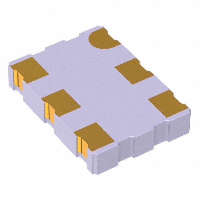
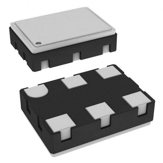
ICGOO电子元器件商城为您提供LTC6930HDCB-4.19#TRMPBF由LINEAR TECHNOLOGY设计生产,在icgoo商城现货销售,并且可以通过原厂、代理商等渠道进行代购。 LTC6930HDCB-4.19#TRMPBF价格参考。LINEAR TECHNOLOGYLTC6930HDCB-4.19#TRMPBF封装/规格:时钟/计时 - 可编程计时器和振荡器, Oscillator, Silicon IC 4.194304MHz 8-DFN (2x3)。您可以下载LTC6930HDCB-4.19#TRMPBF参考资料、Datasheet数据手册功能说明书,资料中有LTC6930HDCB-4.19#TRMPBF 详细功能的应用电路图电压和使用方法及教程。
LTC6930HDCB-4.19#TRMPBF 是 Linear Technology(现为 Analog Devices)生产的一款可编程计时器和振荡器,属于时钟/计时类产品。其应用场景主要包括以下几个方面:

 1. 精确延时控制
LTC6930 提供高精度的延时功能,适用于需要精准时间控制的系统。例如,在工业自动化设备中,它可以用于控制继电器、传感器或执行器的开关时间,确保设备按照预定的时间间隔运行。

 2. 脉冲宽度调制 (PWM)
该芯片可以生成稳定的 PWM 信号,适用于驱动 LED、电机或其他负载的应用场景。例如,在 LED 照明系统中,LTC6930 可以调节亮度或实现呼吸灯效果。

 3. 通信系统中的时钟源
在通信设备中,LTC6930 可作为低抖动的时钟源,为数据传输提供稳定的基准频率。它支持多种输出频率范围,能够满足不同通信协议的需求。

 4. 消费电子产品的定时功能
在消费电子产品中,如家用电器、数码相机或便携式设备,LTC6930 可用于实现定时关机、自动重启或周期性唤醒等功能,从而优化功耗和用户体验。

 5. 医疗设备中的定时控制
在医疗设备中,例如心率监测仪、血糖仪或超声波设备,LTC6930 可以提供高精度的定时功能,确保测量结果的准确性。

 6. 汽车电子中的定时应用
在汽车电子领域,LTC6930 可用于控制车灯闪烁、雨刷器运行周期或发动机点火定时等场景,提供可靠的时间基准。

 7. 测试与测量设备
在测试仪器中,如示波器、信号发生器或数据采集系统,LTC6930 可用作参考时钟,确保信号的稳定性和测量精度。

 特点总结:
- 宽频率范围:支持从毫赫兹到兆赫兹的频率输出。
- 低功耗:适合电池供电设备。
- 高精度:提供稳定的定时和振荡功能。
- 小封装:便于集成到紧凑型设计中。

综上所述,LTC6930HDCB-4.19#TRMPBF 广泛应用于需要高精度定时和振荡功能的各种电子系统中,涵盖工业、消费、医疗、汽车和通信等领域。
| 参数 | 数值 |
| 产品目录 | 集成电路 (IC) |
| 描述 | IC OSC SILICON 4.194304MHZ 8-DFN |
| 产品分类 | |
| 品牌 | Linear Technology |
| 数据手册 | http://www.linear.com/docs/26452 |
| 产品图片 |
|
| 产品型号 | LTC6930HDCB-4.19#TRMPBF |
| rohs | 无铅 / 符合限制有害物质指令(RoHS)规范要求 |
| 产品系列 | - |
| 供应商器件封装 | 8-DFN(3x2) |
| 其它名称 | LTC6930HDCB-4.19#TRMPBF-ND |
| 包装 | 带卷 (TR) |
| 安装类型 | 表面贴装 |
| 封装/外壳 | 8-WFDFN 裸露焊盘 |
| 工作温度 | -40°C ~ 125°C |
| 标准包装 | 500 |
| 电压-电源 | 1.7 V ~ 5.5 V |
| 电流-电源 | 490µA |
| 类型 | 振荡器 - 硅 |
| 计数 | - |
| 频率 | 4.194304MHz |


- 商务部:美国ITC正式对集成电路等产品启动337调查
- 曝三星4nm工艺存在良率问题 高通将骁龙8 Gen1或转产台积电
- 太阳诱电将投资9.5亿元在常州建新厂生产MLCC 预计2023年完工
- 英特尔发布欧洲新工厂建设计划 深化IDM 2.0 战略
- 台积电先进制程称霸业界 有大客户加持明年业绩稳了
- 达到5530亿美元!SIA预计今年全球半导体销售额将创下新高
- 英特尔拟将自动驾驶子公司Mobileye上市 估值或超500亿美元
- 三星加码芯片和SET,合并消费电子和移动部门,撤换高东真等 CEO
- 三星电子宣布重大人事变动 还合并消费电子和移动部门
- 海关总署:前11个月进口集成电路产品价值2.52万亿元 增长14.8%


PDF Datasheet 数据手册内容提取
LTC6930-X.XX 32.768kHz to 8.192MHz Precision µPower Oscillators FeaTures DescripTion n Frequency Error <0.09% Max at 25°C The LTC®6930 series is a family of very low power precision n Start-Up Time <110µs at All Frequencies silicon oscillators with a frequency error less than 0.09%. n 1.7V to 5.5V Single Supply Operation For each oscillator, the user can select one of 8 frequen- n 105µA Typical Supply Current at 32kHz, V+ = 3V cies between 32.768kHz and 8.192MHz. Based on a fixed n 490µA Typical Supply Current at 8MHz, V+ = 3V master oscillator frequency, internal frequency dividers n Typical RMS Period Jitter <0.15% at V+ = 3V between 1 and 128 provide the 8 different frequencies. n No External Components to Set Frequency The LTC6930 requires no external components other than n 5 Options Cover 32.768kHz to 8.192MHz: power supply bypass capacitors. Requiring only a single LTC6930-4.19: 4.194304MHz ÷ N 1.7V to 5.5V supply enables operation from a single Li-Ion LTC6930-5.00: 5.000000MHz ÷ N cell or 2 AA alkaline cells. LTC6930-7.37: 7.372800MHz ÷ N The LTC6930 features a proprietary control architecture LTC6930-8.00: 8.000000MHz ÷ N that allows for ultralow power operation while maintaining LTC6930-8.19: 8.192000MHz ÷ N industry leading accuracy and jitter specifications. The Where N = 1, 2, 4, 8, 16, 32, 64, 128 exceptionally fast start-up time, combined with the low (N Determined by State of DIVA, DIVB, DIVC Pins) power consumption, is ideal for battery operated applica- n –55°C to 125°C Operating Temperature Range tions with frequent power-up cycles. n Tiny 2mm 3mm DFN or MS8 Package Any frequency from 32.768kHz to 8.192MHz can be pro- vided by the factory. Minimum order sizes apply for custom applicaTions frequencies. Please consult LTC Marketing for details. n Digitally Controlled Oscillator L, LT, LTC, LTM, Linear Technology and the Linear logo are registered trademarks and n Microprocessor Clock ThinSOT is a trademark of Linear Technology Corporation. All other trademarks are the property of their respective owners. Protected by U.S. Patents, including 6342817, 6614313. n Power Supply Clock n Portable and Battery Operated Devices Typical applicaTion 4MHz Micropower Clock Generator Typical Frequency Error Distribution V+ = 1.7V TO 5.5V 70 TA = 25°C IS = 325µA AT 3VDC V+ = 3V 60 DIV = 0 1045 UNITS 0.1µF 50 V+ V+ S40 DIVA OUT NIT LTC6930-8.00 4MHz U30 DIVB 20 DIVC 10 GND GND 0 –0.10 –0.05 0 0.05 0.10 6930 TA01a FREQUENCY ERROR (%) 6930 TA01b 6930fe 1 For more information www.linear.com/LTC6930
LTC6930-X.XX absoluTe MaxiMuM raTings (Note 1) Total Supply Voltage Specified Temperature Range (Note 3) (V+ to GND) .............................................–0.3V to 6V LTC6930C ................................................0°C to 70°C Any Input Pin to GND LTC6930I..............................................–40°C to 85°C (DIV Pins) ......................................–0.3V to V+ + 0.3V LTC6930H ..........................................–40°C to 125°C Operating Temperature Range (Note 2) LT6930MP..........................................–55°C to 125°C LTC6930C ............................................–40°C to 85°C Storage Temperature Range ...................–65°C to 150°C LTC6930I..............................................–40°C to 85°C Lead Temperature (Soldering, 10 sec) ..................300°C LTC6930H ..........................................–40°C to 125°C LT6930MP..........................................–55°C to 125°C pin conFiguraTion TOP VIEW V+ 1 8 V+ TOP VIEW V+ 1 8 V+ GND 2 7 OUT 9 GND 2 7 OUT DIVA 3 6 GND DIVA 3 6 GND DIVB 4 5 DIVC DIVB 4 5 DIVC MS8 PACKAGE DCB PACKAGE 8-LEAD PLASTIC MSOP 8-LEAD (2mm × 3mm) PLASTIC DFN TJMAX = 150°C, θJA = 300°C/W (SINGLE-LAYER BOARD) TJMAX = 125°C, θJA = 64°C/W EXPOSED PAD (PIN 9) MUST BE SOLDERED TO GND orDer inForMaTion Lead Free Finish TAPE AND REEL (MINI) TAPE AND REEL PART MARKING* PACKAGE DESCRIPTION TEMPERATURE RANGE LTC6930CDCB-4.19#TRMPBF LTC6930CDCB-4.19#TRPBF LCKT 8-Lead (2mm 3mm) Plastic DFN 0°C to 70°C LTC6930IDCB-4.19#TRMPBF LTC6930IDCB-4.19#TRPBF LCKT 8-Lead (2mm 3mm) Plastic DFN –40°C to 85°C LTC6930HDCB-4.19#TRMPBF LTC6930HDCB-4.19#TRPBF LCKT 8-Lead (2mm 3mm) Plastic DFN –40°C to 125°C LTC6930CDCB-5.00#TRMPBF LTC6930CDCB-5.00#TRPBF LCKV 8-Lead (2mm 3mm) Plastic DFN 0°C to 70°C LTC6930IDCB-5.00#TRMPBF LTC6930IDCB-5.00#TRPBF LCKV 8-Lead (2mm 3mm) Plastic DFN –40°C to 85°C LTC6930HDCB-5.00#TRMPBF LTC6930HDCB-5.00#TRPBF LCKV 8-Lead (2mm 3mm) Plastic DFN –40°C to 125°C LTC6930CDCB-7.37#TRMPBF LTC6930CDCB-7.37#TRPBF LCKW 8-Lead (2mm 3mm) Plastic DFN 0°C to 70°C LTC6930IDCB-7.37#TRMPBF LTC6930IDCB-7.37#TRPBF LCKW 8-Lead (2mm 3mm) Plastic DFN –40°C to 85°C LTC6930HDCB-7.37#TRMPBF LTC6930HDCB-7.37#TRPBF LCKW 8-Lead (2mm 3mm) Plastic DFN –40°C to 125°C LTC6930CDCB-8.00#TRMPBF LTC6930CDCB-8.00#TRPBF LCKX 8-Lead (2mm 3mm) Plastic DFN 0°C to 70°C LTC6930IDCB-8.00#TRMPBF LTC6930IDCB-8.00#TRPBF LCKX 8-Lead (2mm 3mm) Plastic DFN –40°C to 85°C LTC6930HDCB-8.00#TRMPBF LTC6930HDCB-8.00#TRPBF LCKX 8-Lead (2mm 3mm) Plastic DFN –40°C to 125°C LTC6930CDCB-8.19#TRMPBF LTC6930CDCB-8.19#TRPBF LCKY 8-Lead (2mm 3mm) Plastic DFN 0°C to 70°C LTC6930IDCB-8.19#TRMPBF LTC6930IDCB-8.19#TRPBF LCKY 8-Lead (2mm 3mm) Plastic DFN –40°C to 85°C LTC6930HDCB-8.19#TRMPBF LTC6930HDCB-8.19#TRPBF LCKY 8-Lead (2mm 3mm) Plastic DFN –40°C to 125°C TRM = 500 pieces. 6930fe 2 For more information www.linear.com/LTC6930
LTC6930-X.XX orDer inForMaTion LEAD FREE FINISH TAPE AND REEL PART MARKING* PACKAGE DESCRIPTION TEMPERATURE RANGE LTC6930CMS8-4.19#PBF LTC6930CMS8-4.19#TRPBF LTCKZ 8-Lead Plastic MSOP 0°C to 70°C LTC6930IMS8-4.19#PBF LTC6930IMS8-4.19#TRPBF LTCKZ 8-Lead Plastic MSOP –40°C to 85°C LTC6930HMS8-4.19#PBF LTC6930HMS8-4.19#TRPBF LTCKZ 8-Lead Plastic MSOP –40°C to 125°C LTC6930MPMS8-4.19#PBF LTC6930MPMS8-4.19#TRPBF LTCKZ 8-Lead Plastic MSOP –55°C to 125°C LTC6930CMS8-5.00#PBF LTC6930CMS8-5.00#TRPBF LTCLB 8-Lead Plastic MSOP 0°C to 70°C LTC6930IMS8-5.00#PBF LTC6930IMS8-5.00#TRPBF LTCLB 8-Lead Plastic MSOP –40°C to 85°C LTC6930HMS8-5.00#PBF LTC6930HMS8-5.00#TRPBF LTCLB 8-Lead Plastic MSOP –40°C to 125°C LTC6930MPMS8-5.00#PBF LTC6930MPMS8-5.00#TRPBF LTCLB 8-Lead Plastic MSOP –55°C to 125°C LTC6930CMS8-7.37#PBF LTC6930CMS8-7.37#TRPBF LTCLC 8-Lead Plastic MSOP 0°C to 70°C LTC6930IMS8-7.37#PBF LTC6930IMS8-7.37#TRPBF LTCLC 8-Lead Plastic MSOP –40°C to 85°C LTC6930HMS8-7.37#PBF LTC6930HMS8-7.37#TRPBF LTCLC 8-Lead Plastic MSOP –40°C to 125°C LTC6930MPMS8-7.37#PBF LTC6930MPMS8-7.37#TRPBF LTCLC 8-Lead Plastic MSOP –55°C to 125°C LTC6930CMS8-8.00#PBF LTC6930CMS8-8.00#TRPBF LTCLD 8-Lead Plastic MSOP 0°C to 70°C LTC6930IMS8-8.00#PBF LTC6930IMS8-8.00#TRPBF LTCLD 8-Lead Plastic MSOP –40°C to 85°C LTC6930HMS8-8.00#PBF LTC6930HMS8-8.00#TRPBF LTCLD 8-Lead Plastic MSOP –40°C to 125°C LTC6930MPMS8-8.00#PBF LTC6930MPMS8-8.00#TRPBF LTCLD 8-Lead Plastic MSOP –55°C to 125°C LTC6930CMS8-8.19#PBF LTC6930CMS8-8.19#TRPBF LTCLF 8-Lead Plastic MSOP 0°C to 70°C LTC6930IMS8-8.19#PBF LTC6930IMS8-8.19#TRPBF LTCLF 8-Lead Plastic MSOP –40°C to 85°C LTC6930HMS8-8.19#PBF LTC6930HMS8-8.19#TRPBF LTCLF 8-Lead Plastic MSOP –40°C to 125°C LTC6930MPMS8-8.19#PBF LTC6930MPMS8-8.19#TRPBF LTCLF 8-Lead Plastic MSOP –55°C to 125°C Consult LTC Marketing for parts specified with wider operating temperature ranges.*Temperature grades are identified by a label on the shipping container. Consult LTC Marketing for information on lead based finish parts. For more information on lead free part marking, go to: http://www.linear.com/leadfree/ For more information on tape and reel specifications, go to: http://www.linear.com/tapeandreel/ ac elecTrical characTerisTics The l denotes the specifications which apply over the full operating temperature range, otherwise specifications are at T = 25°C. Unless otherwise noted, specifications apply over the full range of A operating supply voltage and frequency output: V+ = 1.7V to 5.5V and all DIV settings with C = 5pF, R = ∞. LOAD LOAD SYMBOL PARAMETER CONDITIONS MIN TYP MAX UNITS Δfi Initial Frequency Accuracy DIVA = DIVB = DIVC = 0, T = 25°C, V+ = 3V 0.08 0.09 % A Δf Frequency Accuracy V+ = 3V – 3.6V (Note 4) LTC6930C l ±0.1 ±0.45 % LTC6930I l ±0.1 ±0.65 % LTC6930H/LTC6930MP l ±0.1 ±1 % V+ = 2V – 3.6V LTC6930C l ±0.1 ±0.52 % LTC6930I l ±0.1 ±0.65 % LTC6930H/LTC6930MP l ±0.1 ±1.1 % V+ = 1.7V – 5.5V LTC6930C l ±0.1 ±0.8 % LTC6930I l ±0.1 ±0.95 % LTC6930H/LTC6930MP l ±0.1 ±1.3 % Δf/ΔT Frequency Drift Over Temperature MS8 Package l 0.0001 %/°C DCB Package l 0.001 %/°C Δf/ΔV Frequency Drift Over Supply l 0.07 %/V Long-Term Frequency Stability (Note 5) l 30 ppm/√kHr 6930fe 3 For more information www.linear.com/LTC6930
LTC6930-X.XX ac elecTrical characTerisTics The l denotes the specifications which apply over the full operating temperature range, otherwise specifications are at T = 25°C. Unless otherwise noted, specifications apply over the full range of A operating supply voltage and frequency output: V+ = 1.7V to 5.5V and all DIV settings with C = 5pF, R = ∞. LOAD LOAD SYMBOL PARAMETER CONDITIONS MIN TYP MAX UNITS RMS Period Jitter DIVA = DIVB = DIVC = 0, V+ = 3V LTC6930-4.19 (4.194304MHz) 320 ps RMS 1.7 ns P-P LTC6930-5.00 (5.000000MHz) 225 ps RMS 1.2 ns P-P LTC6930-7.37 (7.372800MHz) 180 ps RMS 0.97 ns P-P LTC6930-8.00 (8.000000MHz) 130 ps RMS 0.8 ns P-P LTC6930-8.19 (8.192000MHz) 130 ps RMS 0.8 ns P-P Dc elecTrical characTerisTics The l denotes the specifications which apply over the full operating temperature range, otherwise specifications are at T = 25°C. Unless otherwise noted, specifications apply over the full range of A operating supply voltage and frequency output: V+ = 1.7V to 5.5V and all DIV settings with C = 5pF, R = ∞. LOAD LOAD SYMBOL PARAMETER CONDITIONS MIN TYP MAX UNITS V Supply Voltage Applied Between l 1.7 5.5 V S V+ and GND I V+ Combined Supply Current LTC6930-4.19 S,DC DIVA = DIVB = DIVC = 0, V+ = 1.7V l 170 290 µA DIVA = DIVB = DIVC = 0, V+ = 3V l 260 420 µA DIVA = DIVB = DIVC = 0, V+ = 5.5V l 490 750 µA DIVA = DIVB = DIVC = 1, V+ = 1.7V l 80 160 µA DIVA = DIVB = DIVC = 1, V+ = 3V l 105 190 µA DIVA = DIVB = DIVC = 1, V+ = 5.5V l 130 355 µA LTC6930-5.00 DIVA = DIVB = DIVC = 0, V+ = 1.7V l 201 430 µA DIVA = DIVB = DIVC = 0, V+ = 3V l 307 570 µA DIVA = DIVB = DIVC = 0, V+ = 5.5V l 579 960 µA DIVA = DIVB = DIVC = 1, V+ = 1.7V l 95 176 µA DIVA = DIVB = DIVC = 1, V+ = 3V l 124 212 µA DIVA = DIVB = DIVC = 1, V+ = 5.5V l 154 375 µA I V+ Combined Supply Current LTC6930-7.37 S,DC DIVA = DIVB = DIVC = 0, V+ = 1.7V l 296 480 µA DIVA = DIVB = DIVC = 0, V+ = 3V l 453 660 µA DIVA = DIVB = DIVC = 0, V+ = 5.5V l 853 1310 µA DIVA = DIVB = DIVC = 1, V+ = 1.7V l 139 220 µA DIVA = DIVB = DIVC = 1, V+ = 3V l 183 273 µA DIVA = DIVB = DIVC = 1, V+ = 5.5V l 226 440 µA LTC6930-8.00 DIVA = DIVB = DIVC = 0, V+ = 1.7V l 321 520 µA DIVA = DIVB = DIVC = 0, V+ = 3V l 491 740 µA DIVA = DIVB = DIVC = 0, V+ = 5.5V l 926 1380 µA DIVA = DIVB = DIVC = 1, V+ = 1.7V l 151 240 µA DIVA = DIVB = DIVC = 1, V+ = 3V l 198 295 µA DIVA = DIVB = DIVC = 1, V+ = 5.5V l 246 475 µA LTC6930-8.19 DIVA = DIVB = DIVC = 0, V+ = 1.7V l 310 490 µA DIVA = DIVB = DIVC = 0, V+ = 3V l 500 760 µA DIVA = DIVB = DIVC = 0, V+ = 5.5V l 880 1400 µA DIVA = DIVB = DIVC = 1, V+ = 1.7V l 150 270 µA DIVA = DIVB = DIVC = 1, V+ = 3V l 190 325 µA DIVA = DIVB = DIVC = 1, V+ = 5.5V l 210 540 µA V Minimum High Level Input Voltage, l 1.25 1.4 V IH All Digital Input Pins 6930fe 4 For more information www.linear.com/LTC6930
LTC6930-X.XX Dc elecTrical characTerisTics The l denotes the specifications which apply over the full operating temperature range, otherwise specifications are at T = 25°C. Unless otherwise noted, specifications apply over the full range of A operating supply voltage and frequency output: V+ = 1.7V to 5.5V and all DIV settings with C = 5pF, R = ∞. LOAD LOAD SYMBOL PARAMETER CONDITIONS MIN TYP MAX UNITS V Maximum Low Level Input Voltage, l 0.7 1.25 V IL All Digital Input Pins I Digital Input Leakage Current, All 0 < V < V+ l ±1 µA IN IN Digital Input Pins R Output Resistance OUT Pin, V+ = 3V 40 Ω OUT V High Level Output Voltage DIVA = DIVB = DIVC = 0, No Load OH V+ = 5.5V l 5.4 5.5 V V+ = 3V l 2.9 3 V V+ = 2V l 1.8 2 V V+ = 1.7V 1.7 V DIVA = DIVB = DIVC = 0, 1kΩ Load to GND V+ = 5.5V l 5 5.2 V V+ = 3V l 2.6 2.7 V V+ = 2V l 1.5 1.6 V V+ = 1.7V 1.5 V V Low Level Output Voltage DIVA = DIVB = DIVC = 0, No Load OL V+ = 5.5V l 0 0.1 V V+ = 3V l 0 0.1 V V+ = 2V l 0 0.1 V V+ = 1.7V 0 V DIVA = DIVB = DIVC = 0, 1kΩ Load to V+ V+ = 5.5V l 0.3 0.7 V V+ = 3V l 0.3 0.5 V V+ = 2V l 0.3 0.35 V V+ = 1.7V 0.3 V TiMing characTerisTics The l denotes the specifications which apply over the full operating temperature range, otherwise specifications are at T = 25°C. Unless otherwise noted, specifications apply over the full range of operating supply A voltage and frequency output: V+ = 1.7V to 5.5V and f = 32.768kHz to 8.192MHz with C = 5pF, R = ∞. OUT LOAD LOAD SYMBOL PARAMETER CONDITIONS MIN TYP MAX UNITS t Output Rise/Fall Time (10% to 90%) V+ = 3V 3 ns rf DCY Duty Cycle DIVA = DIVB = DIVC = 0; V+ = 2V to 5.5V l 35 50 65 % DIVA = DIVB = DIVC = 0 l 35 50 70 % DIVA or DIVB or DIVC ≠ 0 l 48 50 52 % D DIV to OUT Delay Edge of DIV Signal to 1st Accurate Output Cycle 1 Cycle DIV D Power On Delay V+ > 1.7V to 1st Accurate Output Cycle l 110 µs PON Note 1: Stresses beyond those listed under Absolute Maximum Ratings the LTC6930 family of parts are defined as follows: may cause permanent damage to the device. Exposure to any Absolute LTC6930-4.19 f = 4.194304MHz NOM Maximum Rating condition for extended periods may affect device LTC6930-5.00 f = 5.000000MHz NOM reliability and lifetime. LTC6930-7.37 f = 7.372800MHz NOM Note 2: LTC6930C is guaranteed functional over the operating range of LTC6930-8.00 f = 8.000000MHz –40°C to 85°C. NOM LTC6930-8.19 f = 8.192000MHz Note 3: The LTC6930C is guaranteed to meet specified performance from NOM 0°C to 70°C. The LTC6930C is designed, characterized and expected to Note 5: Long-term drift of silicon oscillators is primarily due to the meet specified performance from –40°C to 85°C but is not tested or QA movement of ions and impurities within the silicon and is tested at 30°C sampled at these temperatures. The LTC6930I is guaranteed to meet under otherwise nominal operating conditions. Long-term drift is specified specified performance from –40°C to 85°C. The LTC6930H is guaranteed as ppm/√kHr due to the typically non-linear nature of the drift. To calculate to meet specified performance from –40°C to 125°C. The LTC6930MP is drift for a set time period, translate that time into thousands of hours, guaranteed to meet specified performance from –55°C to 125°C. take the square root and multiply by the typical drift number. For instance, a year is 8.77kHr and would yield a drift of 89ppm at 30ppm/√kHr. Drift Note 4: Frequency accuracy and frequency drift are defined as deviation without power applied to the device may be approximated as 1/10th of the from the nominal frequency or the nominal frequency divided by the drift with power, or 3ppm/√kHr for a 30ppm/√kHr device. integer set through the DIV pins for each part. The nominal frequency for 6930fe 5 For more information www.linear.com/LTC6930
LTC6930-X.XX Typical perForMance characTerisTics Typical Frequency Error Typical Frequency Error Typical Frequency Error vs Temperature, MS8 Package vs Temperature, DFN Package vs Supply Voltage (Note 3) (Note 3) 3V) 0.25 TA = 25°C 0.60 V+ = 3V 0.60 V+ = 3V O 0.20 T ED 0.15 0.40 0.40 MALIZ 0.10 8.19MHz R (%) 0.20 R (%) 0.20 OR 0.05 RO RO N R R %, 0 4.19MHz Y E 0 Y E 0 OR (–0.05 ENC ENC ENCY ERR––00..1150 FREQU ––00..2400 FREQU ––00..2400 U Q–0.20 E R F–0.25 –0.60 –0.60 1.7 2.7 3.7 4.7 –55 –25 –5 15 35 55 75 95 115125 –45 –25 –5 15 35 55 75 95 115125 SUPPLY VOLTAGE (V) TEMPERATURE (°C) TEMPERATURE (°C) 4216 G01 4216 G02 4216 G03 Typical Supply Current Typical Supply Current Typical Supply Current vs DIV Setting vs Load Capacitance vs Supply Voltage 600 TA = 25°C 2000 LTC6930-8.19 V+ = 3V 1000 DIVIDE = 1 1800 TA = 25°C 900 TA = 25°C 500 1600 DIV = 1 800 NT (µA) 400 NT (µA)11240000 DDDIIIVVV === 248 DDDIIIVVV === 136624 NT (µA) 670000 8.192MHz RE 8.192MHz, 1.7V RE DIV = 128 RE UR 300 UR1000 UR 500 C C C 4.194MHz LY 8.192MHz, 3V LY 800 LY 400 UPP 200 UPP 600 UPP 300 S S S 400 200 100 200 100 4.194MHz, 1.7V 4.194MHz, 3V 0 0 0 1 10 100 0 10 20 30 40 50 60 1.7 2.2 2.7 3.2 3.7 4.2 4.7 5.2 DIV SETTING (LOG) LOAD CAPACITANCE (pF) SUPPLY VOLTAGE (V) 6930 G04 4216 G05 4216 G06 Typical Supply Current vs Temperature (Note 3) Typical Output Spectrum, 8MHz Typical Output Waveform, 8MHz 700 CLOAD = 5pF 600 A) NT (µ 500 3V, 8.192MHz E R UR 400 10dB/DIV 0.45V/DIV C Y 3V, 4.19MHz L PP 300 U S ER 200 W O P 100 400kHz/DIV 6930 G08 40ns/DIV 6930 G09 LTC6930-8.00 1.7V, 32kHz 0 CLOAD = 12pF –55 5 55 105 TEMPERATURE (°C) 4216 G07 6930fe 6 For more information www.linear.com/LTC6930
LTC6930-X.XX Typical perForMance characTerisTics Typical Jitter vs Supply in Divide by 1 Mode Typical Period Jitter Histogram Typical Jitter vs Divider Setting 0.30 TA = 25°C 400 LTC6930-8.19 V+ = 3V 0.16 V+ = 3V TA = 25°C 0.14 TA = 25°C 0.25 DIVIDE = 1 4.194MHz 300 0.12 MS)0.20 MS)0.10 TTER (% R0.15 8.192MHz SAMPLES200 TTER (% R00..0086 4.194MHz JI0.10 JI 100 0.04 8.192MHz 0.05 0.02 0 0 0 1.7 2.2 2.7 3.2 3.7 4.2 4.7 5.2 –450 –300 –150 0 150 300 450 1 10 100 SUPPLY VOLTAGE (V) PERIOD ERROR (ps) DIV SETTING (LOG) 4216 G10 4216 G11 6930 G12 Typical Output Rise/Fall Time Typical Output Resistance Typical Output Duty Cycle vs Supply vs Supply Voltage vs Supply and Divide Ratio 4.5 100 60 CLOAD = 5pF TA = 25°C 4.0 TA = 25°C 90 58 OUTPUT RISE/FALL TIME (ns) 332211......505050 FALLR ITSIME TEIME OUTPUT RESISTANCE (Ω) 86724350000000 DUTY CYCLE (%) 55544456244860 DIVIDE 8BMYH >z1, DIVIDE BY4 M1Hz, DIVIDE BY 1 0.5 10 42 0 0 40 1.7 2.2 2.7 3.2 3.7 4.2 4.7 5.2 1.7 2.2 2.7 3.2 3.7 4.2 4.7 5.2 1.7 2.2 2.7 3.2 3.7 4.2 4.7 5.2 SUPPLY VOLTAGE (V) SUPPLY VOLTAGE (V) SUPPLY VOLTAGE (V) 4216 G13 4216 G14 4216 G15 Typical Frequency Settling Typical Frequency Error Typical Output Waveform from Power-Up vs Time (Long-Term Drift) at DIV Pin Change 10 500 25 PARTS SHOWN 5 400 TA = 30°C 300 %) 0 m) ROR ( –5 CY (pp 120000 R N E E QUENCY ––1105 A FREQU–1 0 00 FRE –20 DELT–200 –300 –25 400ns/DIV 6930 G18 –400 –30 –500 0 50 100 150 200 0 500 1000 1500 2000 2500 3000 TIME SINCE POWER APPLIED (µs) TIME (HOURS) 4216 G16 4216 G17 6930fe 7 For more information www.linear.com/LTC6930
LTC6930-X.XX pin FuncTions V+ (Pins 1, 8): Positive Supply Pins. Each supply pin OUT (Pin 7): Oscillator Output. Drives up to 50pF capaci- should be bypassed directly to the neighboring GND pin tive or 1k resistive load (Refer to Supply Current vs Load with a 0.1µF ceramic capacitor, and must be externally Capacitance in Typical Performance Characteristics sec- connected to the other V+ pin (see recommended layout). tion). Typical series resistance is less than 80Ω at 1.7V and less than 40Ω at 3V supply. The output trace should GND (Pins 2, 6): Ground Pins. Each should be connected be isolated as much as possible from Pin 1 and Pin 2. to a low inductance ground plane and must be connected The OUT pin is held low during start-up, and remains free to the other GND pin and on the DFN package, Pin 9. from glitches and runt pulses during DIV pin switching. DIVA, DIVB, DIVC (Pins 3, 4, 5): Output Prescaler. Se- Exposed Pad (Pin 9, DFN Only): The Exposed Pad must lects divide ratio of master oscillator frequency used to be soldered to a PCB plane connected to GND. generate the output. See frequency setting Table 1 for function. These are standard CMOS logic inputs with a typical threshold of 1.25V applicaTions inForMaTion Theory of Operation Output Driver and Loading The LTC6930 is an entirely self contained all silicon oscil- The output of the LTC6930 is a low series resistance 40Ω lator which consists of a master oscillator, a control loop CMOS driver with controlled rise/fall times to limit RF and an output frequency divider. The master oscillator interference and power supply spikes generated by the operates between 4.2MHz and 8.2MHz and is factory output while preserving the ability to drive low impedance programmed. The master oscillator frequency is accurately loads. Especially at high frequencies, the capacitive loading maintained over temperature and environmental extremes of the output of the LTC6930 may cause the majority of by a proprietary switched capacitor feedback loop. the power supply dissipation of the part. Each LTC6930 oscillator has an output frequency divider The LTC6930 supply current is specified at an output load which is controlled via the DIVA, DIVB and DIVC inputs. of 5pF, which is equivalent to two standard HC logic inputs. The divider divides the master frequency by 2N, where N The portion of the power supply current needed to drive is an integer from 0 to 7 (divider ranges from 1 to 128). a capacitive load may be calculated as: See Table 1 for the full range of frequencies covered by I = C • V • f SUPPLY LOAD SWING OSC the LTC6930 family. where C is the 5pF load capacitance, V is the LOAD SWING The presence of two sets of supply pins and careful internal voltage swing, in this case up to 5.5V, and f is the fre- OSC layout reduce interference between the oscillator output quency of the oscillator output. Driving a 5.5V swing into a and the control loop. This allows the LTC6930 to provide 5pF load at 8MHz takes an average of 220µA. To calculate a clean output frequency with very little deterministic jitter, the portion of the supply current needed for a 50pF load, even in cases of heavy output loading and noisy operating simply substitute 50pF for C in the same equation: LOAD environments. 50pF • 5.5V • 8MHz = 2.2mA The supply voltage of the LTC6930 is internally regulated to maintain a very low frequency drift over supply. The majority of this power is expended during the rise and fall time of the output signal, not while it is in a steady 6930fe 8 For more information www.linear.com/LTC6930
LTC6930-X.XX applicaTions inForMaTion state. The 2ns rise and fall times of the LTC6930 mean that Start-Up Time the instantaneous power supply current required during The start-up time of the LTC6930 is typically 50µs from the the rise and fall portions of the waveform is much greater time that valid power is applied to the first output pulse. than the average. The output is held low for the first 50µs to prevent any The instantaneous power supply current may be calculated glitches, runt pulses, or invalid frequency output during by a similar formula: start-up. 1 I =C •V • PEAK LOAD SWING Long-Term Drift t rf Long-term stability of silicon oscillators is specified in where t is the rise/fall time of the signal. In this case, ppm/√kHr, which is typical of other silicon devices such rf 14mA spikes are generated by driving 5.5V into a 5pF load. as operational amplifiers and voltage references. Because drift in silicon-based oscillators is generated primarily by Power is supplied to the output driver of the LTC6930 movement of ions in the silicon, most of the drift is ac- from the V+ and GND pins on each side of the output pin complished early in the life of the device and the drift can (Pins 6 and 8). Allowances must be made in the design be expected to level off in the long term. The ppm/√kHr to provide for output load related supply current spikes, unit models this time variant decay. Crystal oscillators especially in high accuracy applications. A 0.1µF ceramic are often specified with drift measured in ppm/year be- capacitor connected between V+ and GND (Pins 6 and 8) cause their drift mechanism is different. A comparison of as close as possible to the device will decouple the rest various drift rates over a five year time period is shown of the circuit from spikes caused by powering a capacitive in Figure 2. output load of up to 50pF. See Figure 1. When calculating the amount of drift to be expected, it is important to consider the entire time in the calculation, because the relationship to time is not linear. The drift for C1 V+ 0.1µF C2 0.045 OUT 0.1µF 0.040 GND 0.035 0.030 60ppm/√kHr %) 0.025 T ( GND RIF 0.020 D 6930 F01 0.015 30ppm/√kHr 0.010 Figure 1. Recommended Layout 0.005 10ppm/√kHr 0 Switching the DIV Pins 0 20 40 60 80 MONTHS 6930 F02 The LTC6930 is designed to quickly and cleanly respond to the digital inputs. The output will respond to the DIV Figure 2. 5 Year Drift at Various Rates pins within a single clock cycle without introducing any sliver or runt pulses. 6930fe 9 For more information www.linear.com/LTC6930
LTC6930-X.XX applicaTions inForMaTion 5 years is not 5 times the drift for one year. A sample cal- Setting the Frequency culation for drift over 5 years at 30ppm/√kHr is as follows: The output frequency of the LTC6930 is chosen from the 5 years • 365.25 days/year • 24 hours/day = 43,830 values in Table 1 and set using the DIV pins, as noted hours = 43.830kHr in the table. Master oscillator frequency is preset in the factory, and the DIV pins select an internal binary divider √43.830kHr = 6.62√kHr of up to 128. 6.62√kHr • 30ppm/√kHr = 0.0198% over 5 years. For example, if the desired oscillator output frequency Drift calculations assume that the part is in continuous is 2.5MHz, finding 2.5MHz in Table 1 shows that the operation during the entire time period of the calculation. LTC6930-5.00 should be ordered, having a master The movement of ions which results in drift is usually aided oscillator frequency of 5MHz, and a DIV value of [001] by electric fields in the operating parts, and the typical drift should be used. This would equate to grounding DIVC spec applies while the part is powered up. Conservative and DIVB, while connecting DIVA to the positive supply. calculations would use a tenth of the drift specification for Frequencies other than those shown in Table 1 may time when power is not applied to the part. be requested. Table 1. Frequency Setting and Available Frequencies ÷1 ÷2 ÷4 ÷8 ÷16 ÷32 ÷64 ÷128 DIV Pin Settings [DIVC][DIVB][DIVA] 000 001 010 011 100 101 110 111 LTC6930-4.19 4.194304MHz 2.097152MHz 1.048576MHz 524.288kHz 262.144kHz 131.072kHz 65.536kHz 32.768kHz LTC6930-5.00 5.000MHz 2.500MHz 1.250MHz 625.0kHz 312.5kHz 156.25kHz 78.125kHz 39.0625kHz LTC6930-7.37 7.3728MHz 3.6864MHz 1.8432MHz 921.6kHz 460.8kHz 230.4kHz 115.2kHz 57.6kHz LTC6930-8.00 8.000MHz 4.000MHz 2.000MHz 1000kHz 500.0kHz 250.0kHz 125.0kHz 62.5kHz LTC6930-8.19 8.192MHz 4.096MHz 2.048MHz 1024kHz 512.0kHz 256.0kHz 128.0kHz 64.0kHz 6930fe 10 For more information www.linear.com/LTC6930
LTC6930-X.XX package DescripTion DCB Package 8-Lead Plastic DFN (2mm × 3mm) (Reference LTC DWG # 05-08-1718 Rev A) 0.70 ±0.05 3.50 ±0.05 1.35 ±0.05 1.65 ± 0.05 2.10 ±0.05 PACKAGE OUTLINE 0.25 ± 0.05 0.45 BSC 1.35 REF RECOMMENDED SOLDER PAD PITCH AND DIMENSIONS APPLY SOLDER MASK TO AREAS THAT ARE NOT SOLDERED 2.00 ±0.10 R = 0.115 0.40 ± 0.10 (2 SIDES) TYP R = 0.05 5 8 TYP 1.35 ±0.10 3.00 ±0.10 1.65 ± 0.10 (2 SIDES) PIN 1 NOTCH PIN 1 BAR R = 0.20 OR 0.25 TOP MARK × 45° CHAMFER (SEE NOTE 6) (DCB8) DFN 0106 REV A 4 1 0.23 ± 0.05 0.200 REF 0.75 ±0.05 0.45 BSC 1.35 REF BOTTOM VIEW—EXPOSED PAD 0.00 – 0.05 NOTE: 1. DRAWING IS NOT A JEDEC PACKAGE OUTLINE 2. DRAWING NOT TO SCALE 3. ALL DIMENSIONS ARE IN MILLIMETERS 4. DIMENSIONS OF EXPOSED PAD ON BOTTOM OF PACKAGE DO NOT INCLUDE MOLD FLASH. MOLD FLASH, IF PRESENT, SHALL NOT EXCEED 0.15mm ON ANY SIDE 5. EXPOSED PAD SHALL BE SOLDER PLATED 6. SHADED AREA IS ONLY A REFERENCE FOR PIN 1 LOCATION ON THE TOP AND BOTTOM OF PACKAGE 6930fe 11 For more information www.linear.com/LTC6930
LTC6930-X.XX package DescripTion MS8 Package 8-Lead Plastic MSOP (Reference LTC DWG # 05-08-1660 Rev G) 0.889 ±0.127 (.035 ±.005) 5.10 3.20 – 3.45 (.201) (.126 – .136) MIN 3.00 ±0.102 0.42 ± 0.038 0.65 (.118 ±.004) 0.52 (.0165 ±.0015) (.0256) (NOTE 3) 8 7 6 5 (.0205) TYP BSC REF RECOMMENDED SOLDER PAD LAYOUT 3.00 ±0.102 4.90 ±0.152 DETAIL “A” (.118 ±.004) 0.254 (.193 ±.006) (NOTE 4) (.010) 0° – 6° TYP GAUGE PLANE 1 2 3 4 0.53 ±0.152 (.021 ±.006) 1.10 0.86 (.043) (.034) DETAIL “A” MAX REF 0.18 (.007) SEATING PLANE 0.22 – 0.38 0.1016 ±0.0508 (.009 – .015) (.004 ±.002) TYP 0.65 MSOP (MS8) 0213 REV G (.0256) NOTE: BSC 1. DIMENSIONS IN MILLIMETER/(INCH) 2. DRAWING NOT TO SCALE 3. DIMENSION DOES NOT INCLUDE MOLD FLASH, PROTRUSIONS OR GATE BURRS. MOLD FLASH, PROTRUSIONS OR GATE BURRS SHALL NOT EXCEED 0.152mm (.006") PER SIDE 4. DIMENSION DOES NOT INCLUDE INTERLEAD FLASH OR PROTRUSIONS. INTERLEAD FLASH OR PROTRUSIONS SHALL NOT EXCEED 0.152mm (.006") PER SIDE 5. LEAD COPLANARITY (BOTTOM OF LEADS AFTER FORMING) SHALL BE 0.102mm (.004") MAX 6930fe 12 For more information www.linear.com/LTC6930
LTC6930-X.XX revision hisTory (Revision history begins at Rev C) REV DATE DESCRIPTION PAGE NUMBER C 1/11 Revised the option for LTC6930-7.37 under Features. 1 D 2/11 Added LTC6930CMS8-4.19 to the Order Information section. 3 E 5/15 Added MP-Grade 1-3, 5, 6 6930fe Information furnished by Linear Technology Corporation is believed to be accurate and reliable. 13 However, no responsibility is assumed for its use. Linear Technology Corporation makes no representa- tion that the interconneFcotior nm oof irtse ciinrcfouirtms aast dioensc wribwedw h.leinreeina rw.cilol nmot/ LinTfCrin6g9e3 o0n existing patent rights.
LTC6930-X.XX Typical applicaTion Dual, Matched, Digitally Programmable, Lowpass Filter, 2kHz to 256kHz 5V VIN1 1 IN+ OUT 8 VOUT1 2 IN– V+ 7 5V 3.48k 3 6 0.1µF GND RX Amplitude Response 2k 1µF LTC1569-7 4 V– DIV/CLK 5 0 5V VIN2 1 IN+ OUT 8 VOUT2 –20 2 IN– V+ 7 5V 3.48k 3 6 0.1µF B)–40 fCUTOFF = 8kHz 32kHz 128kHz GND RX N (d 2k 1µF LTC1569-7 AI 4 V– DIV/CLK 5 G–60 5V –80 0.1µF 1 V+ V+ 8 –100 0.1µF 2 7 fOSC 1 10 100 1000 GND OUT FREQUENCY (kHz) 3 6 DIVA DIVA GND LTC6930-8.192 4 5 DIVB DIVB DIVC DIVC 6930 TA02 DIVC, DIVB, DIVA 000 001 010 011 100 101 110 111 f 256kHz 128kHz 64kHz 32kHz 16kHz 8kHz 4kHz 2kHz CUTOFF relaTeD parTs PART NUMBER DESCRIPTION COMMENTS LTC1799 1kHz to 33MHz ThinSOT™ Oscillator, Resistor Set Wide Frequency Range LTC6900 1kHz to 20MHz ThinSOT Oscillator, Resistor Set Low Power, Wide Frequency Range LTC6902 Multiphase Oscillator with Spread Spectrum Modulation 2-, 3- or 4-Phase Outputs LTC6903/LTC6904 1kHz to 68MHz Serial Port Programmable Oscillator 0.1% Frequency Resolution, I2C or SPI Interface LTC6905 17MHz to 170MHz ThinSOT Oscillator, Resistor Set High Frequency, 100µs Start-Up, 7ps RMS Jitter LTC6905-XXX Fixed Frequency ThinSOT Oscillator Family, Up to 133MHz No Trim Components Required LTC6906 Micropower 10kHz to 1MHz ThinSOT Oscillator, Resistor Set 12µA Supply Current at 100kHz, 0.65% Frequency Accuracy LTC6907 Micropower 40kHz to 4MHz ThinSOT Oscillator, Resistor Set 36µA Supply Current at 400kHz, 0.65% Frequency Accuracy LTC6908 Multiphase Oscillator with Spread Spectrum Modulation 2 Outputs Shifted by Either 180° or 90° LTC6909 Multiphase Oscillator with Spread Spectrum Modulation 8 Outputs, Configurable Phase Separation from 45° to 120° 6930fe 14 Linear Technology Corporation LT 0515 REV E • PRINTED IN USA 1630 McCarthy Blvd., Milpitas, CA 95035-7417 For more information www.linear.com/LTC6930 (408) 432-1900 ● FAX: (408) 434-0507 ● www.linear.com/LTC6930 LINEAR TECHNOLOGY CORPORATION 2008
Mouser Electronics Authorized Distributor Click to View Pricing, Inventory, Delivery & Lifecycle Information: A nalog Devices Inc.: LTC6930HDCB-4.19#PBF LTC6930HMS8-5.00#PBF LTC6930CDCB-4.19#PBF LTC6930CMS8-5.00#PBF LTC6930CDCB-5.00#TRMPBF LTC6930IDCB-5.00#TRMPBF LTC6930IDCB-5.00#PBF LTC6930IDCB-7.37#TRPBF LTC6930HDCB-5.00#TRMPBF LTC6930MPMS8-4.19#PBF LTC6930IMS8-7.37#TRPBF LTC6930HDCB-7.37#TRPBF LTC6930CDCB-7.37#TRPBF LTC6930IDCB-8.19#TRMPBF LTC6930CDCB-5.00#TRPBF LTC6930IMS8-8.19#PBF LTC6930CMS8-7.37#TRPBF LTC6930IMS8-8.00#PBF LTC6930HDCB-8.19#PBF LTC6930HDCB-8.00#PBF LTC6930MPMS8-8.00#PBF LTC6930HDCB-5.00#TRPBF LTC6930HMS8-8.00#PBF LTC6930HDCB-8.00#TRMPBF LTC6930HMS8-8.19#TRPBF LTC6930HMS8-5.00#TRPBF LTC6930IDCB-7.37#PBF LTC6930CMS8-8.19#TRPBF LTC6930HMS8-8.00#TRPBF LTC6930IDCB-8.00#TRPBF LTC6930IMS8-8.19#TRPBF LTC6930MPMS8-7.37#PBF LTC6930CMS8-5.00#TRPBF LTC6930CMS8-8.00#PBF LTC6930MPMS8-7.37#TRPBF LTC6930IDCB-4.19#PBF LTC6930HDCB-4.19#TRMPBF LTC6930MPMS8-8.00#TRPBF LTC6930CDCB-8.00#PBF LTC6930IDCB- 5.00#TRPBF LTC6930CMS8-4.19#PBF LTC6930IMS8-5.00#TRPBF LTC6930CMS8-8.00#TRPBF LTC6930IDCB- 8.00#PBF LTC6930HMS8-4.19#PBF LTC6930MPMS8-8.19#PBF LTC6930MPMS8-4.19#TRPBF LTC6930IDCB- 4.19#TRMPBF LTC6930HDCB-8.19#TRPBF LTC6930IMS8-4.19#PBF LTC6930MPMS8-8.19#TRPBF LTC6930HDCB-8.19#TRMPBF LTC6930CDCB-5.00#PBF LTC6930CDCB-8.19#TRMPBF LTC6930IDCB- 4.19#TRPBF LTC6930HDCB-8.00#TRPBF LTC6930HMS8-4.19#TRPBF LTC6930IMS8-4.19#TRPBF LTC6930CDCB-7.37#TRMPBF LTC6930CDCB-4.19#TRMPBF LTC6930HDCB-7.37#PBF LTC6930HDCB-5.00#PBF LTC6930CMS8-7.37#PBF LTC6930CMS8-4.19#TRPBF LTC6930CMS8-8.19#PBF LTC6930IDCB-8.19#PBF LTC6930HDCB-7.37#TRMPBF LTC6930HMS8-7.37#PBF LTC6930HDCB-4.19#TRPBF LTC6930MPMS8- 5.00#TRPBF LTC6930HMS8-7.37#TRPBF LTC6930IDCB-8.00#TRMPBF LTC6930CDCB-8.00#TRMPBF LTC6930CDCB-7.37#PBF LTC6930CDCB-8.19#TRPBF LTC6930HMS8-8.19#PBF LTC6930CDCB-4.19#TRPBF LTC6930IMS8-5.00#PBF LTC6930IMS8-7.37#PBF LTC6930IDCB-8.19#TRPBF LTC6930IMS8-8.00#TRPBF LTC6930CDCB-8.00#TRPBF LTC6930CDCB-8.19#PBF LTC6930MPMS8-5.00#PBF LTC6930IDCB-7.37#TRMPBF