ICGOO在线商城 > 集成电路(IC) > 数据采集 - 模数转换器 > LTC2226IUH#PBF

 Datasheet下载
- 型号: LTC2226IUH#PBF
- 制造商: LINEAR TECHNOLOGY
- 库位|库存: xxxx|xxxx
- 要求:
| 数量阶梯 | 香港交货 | 国内含税 |
| +xxxx | $xxxx | ¥xxxx |
查看当月历史价格
查看今年历史价格
LTC2226IUH#PBF产品简介:
ICGOO电子元器件商城为您提供LTC2226IUH#PBF由LINEAR TECHNOLOGY设计生产,在icgoo商城现货销售,并且可以通过原厂、代理商等渠道进行代购。 LTC2226IUH#PBF价格参考。LINEAR TECHNOLOGYLTC2226IUH#PBF封装/规格:数据采集 - 模数转换器, 12 Bit Analog to Digital Converter 1 Input 1 Pipelined 32-QFN (5x5)。您可以下载LTC2226IUH#PBF参考资料、Datasheet数据手册功能说明书,资料中有LTC2226IUH#PBF 详细功能的应用电路图电压和使用方法及教程。
LTC2226IUH#PBF 是由 Linear Technology(现为 Analog Devices 旗下公司)生产的一款高速、低功耗的14位模数转换器(ADC),采样率可达125MSPS。该器件广泛应用于需要高精度和高速信号处理的场合。

其主要应用场景包括:

1. 通信系统:如基站接收器、无线基础设施设备,用于将射频前端接收到的中频信号数字化处理。
2. 测试与测量设备:如示波器、频谱分析仪等,用于高精度采集和分析模拟信号。
3. 工业控制与自动化:在高精度传感器信号采集系统中实现快速数据转换。
4. 医疗成像设备:如超声波设备中的信号采集部分,要求高分辨率与高速并存的应用。
5. 雷达与军事电子系统:用于实时信号采集与处理,满足高性能与稳定性需求。

该芯片具备良好的动态性能(如高SNR和SFDR),适合对信号完整性要求高的应用。此外,其低功耗特性也适用于便携式或高密度系统设计。
| 参数 | 数值 |
| 产品目录 | 集成电路 (IC) |
| 描述 | IC ADC 12BIT 25MSPS SAMPL 32-QFN |
| 产品分类 | |
| 品牌 | Linear Technology |
| 数据手册 | http://www.linear.com/docs/5237 |
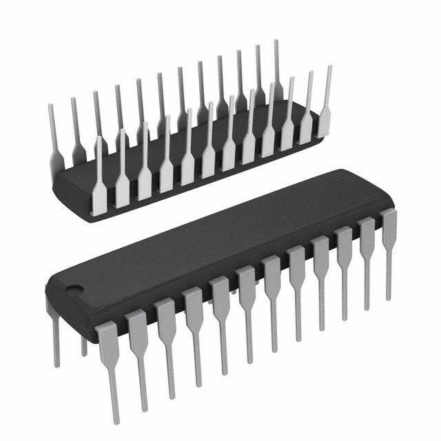
| 产品图片 |
|
| 产品型号 | LTC2226IUH#PBF |
| rohs | 无铅 / 符合限制有害物质指令(RoHS)规范要求 |
| 产品系列 | - |
| 位数 | 12 |
| 供应商器件封装 | 32-QFN(5x5) |
| 其它名称 | LTC2226IUHPBF |
| 包装 | 管件 |
| 安装类型 | 表面贴装 |
| 封装/外壳 | 32-WFQFN 裸露焊盘 |
| 工作温度 | -40°C ~ 85°C |
| 数据接口 | 并联 |
| 标准包装 | 73 |
| 特性 | - |
| 电压源 | 单电源 |
| 转换器数 | 1 |
| 输入数和类型 | 1 个单端,双极; 1 个差分,双极 |
| 配用 | /product-detail/zh/DC782A-J/DC782A-J-ND/4766037 |
| 采样率(每秒) | 25M |


- 商务部:美国ITC正式对集成电路等产品启动337调查
- 曝三星4nm工艺存在良率问题 高通将骁龙8 Gen1或转产台积电
- 太阳诱电将投资9.5亿元在常州建新厂生产MLCC 预计2023年完工
- 英特尔发布欧洲新工厂建设计划 深化IDM 2.0 战略
- 台积电先进制程称霸业界 有大客户加持明年业绩稳了
- 达到5530亿美元!SIA预计今年全球半导体销售额将创下新高
- 英特尔拟将自动驾驶子公司Mobileye上市 估值或超500亿美元
- 三星加码芯片和SET,合并消费电子和移动部门,撤换高东真等 CEO
- 三星电子宣布重大人事变动 还合并消费电子和移动部门
- 海关总署:前11个月进口集成电路产品价值2.52万亿元 增长14.8%


PDF Datasheet 数据手册内容提取
LTC2228/LTC2227/LTC2226 12-Bit, 65/40/25Msps Low Power 3V ADCs FEATURES DESCRIPTION n Sample Rate: 65Msps/40Msps/25Msps The LTC®2228/LTC2227/LTC2226 are 12-bit 65Msps/ n Single 3V Supply (2.7V to 3.4V) 40Msps/25Msps, low power 3V A/D converters designed n Low Power: 205mW/120mW/75mW for digitizing high frequency, wide dynamic range signals. n 71.3dB SNR The LTC2228/LTC2227/LTC2226 are perfect for demand- n 90dB SFDR ing imaging and communications applications with AC n No Missing Codes performance that includes 71.3dB SNR and 90dB SFDR n Flexible Input: 1V to 2V Range for signals at the Nyquist frequency. P-P P-P n 575MHz Full Power Bandwidth S/H DC specs include ±0.3LSB INL (typ), ±0.15LSB DNL (typ) n Clock Duty Cycle Stabilizer and no missing codes over temperature. The transition n Shutdown and Nap Modes noise is a low 0.25LSB . n Pin Compatible Family RMS 125Msps: LTC2253 (12-Bit), LTC2255 (14-Bit) A single 3V supply allows low power operation. A separate 105Msps: LTC2252 (12-Bit), LTC2254 (14-Bit) output supply allows the outputs to drive 0.5V to 3.6V 80Msps: LTC2229 (12-Bit), LTC2249 (14-Bit) logic. 65Msps: LTC2228 (12-Bit), LTC2248 (14-Bit) A single-ended CLK input controls converter operation. An 40Msps: LTC2227 (12-Bit), LTC2247 (14-Bit) optional clock duty cycle stabilizer allows high performance 25Msps: LTC2226 (12-Bit), LTC2246 (14-Bit) at full speed for a wide range of clock duty cycles. 10Msps: LTC2225 (12-Bit), LTC2245 (14-Bit) n 32-Pin (5mm × 5mm) QFN Package L, LT, LTC and LTM are registered trademarks of Linear Technology Corporation. All other trademarks are the property of their respective owners. APPLICATIONS n Wireless and Wired Broadband Communication n Imaging Systems n Ultrasound n Spectral Analysis n Portable Instrumentation TYPICAL APPLICATION LTC2228: SNR vs Input Frequency, –1dB, 2V Range, 65Msps REFH FLEXIBLE 72 REFL REFERENCE OVDD 71 + D11 ANINALPOUGT –INSP/HUT PAIDP1C2E -LCBIONITREDE CORLROEGCICTION DORUITVPEURTS ••• R (dBFS) 70 D0 N S OGND 69 CLOCK/DUTY CYCLE CONTROL 68 0 50 100 150 200 222876 TA01 INPUT FREQUENCY (MHz) CLK 2228 G09 222876fb 1
LTC2228/LTC2227/LTC2226 ABSOLUTE MAXIMUM RATINGS PIN CONFIGURATION OV = V (Notes 1, 2) DD DD Supply Voltage (V ) ..................................................4V DD TOP VIEW DAnigailtoagl OInuptpuut tV Gorltoaugned ( NVoolttea g3e) . .(.O..G..–N0D.3) .V.. .t.o.. .(V–0.3 V+ 0to.3 1VV) VDD VCM SENSE MODE OF D11 D10 D9 DD 32 31 30 29 28 27 26 25 Digital Input Voltage ......................–0.3V to (V + 0.3V) DD AIN+ 1 24 D8 Digital Output Voltage ................–0.3V to (OVDD + 0.3V) AIN– 2 23 D7 Power Dissipation .............................................1500mW REFH 3 22 D6 Operating Temperature Range REFH 4 21 OVDD 33 LTC2228C, LTC2227C, LTC2226C.............0°C to 70°C REFL 5 20 OGND LTC2228I, LTC2227I, LTC2226I ............–40°C to 85°C REFL 6 19 D5 Storage Temperature Range ...................–65°C to 125°C VDD 7 18 D4 GND 8 17 D3 9 10 11 12 13 14 15 16 K N E C C 0 1 2 L D O N N D D D C H S UH PACKAGE 32-LEAD (5mm (cid:115) 5mm) PLASTIC QFN TJMAX = 125°C, θJA = 34°C/W EXPOSED PAD (PIN 33) IS GND, MUST BE SOLDERED TO PCB ORDER INFORMATION LEAD FREE FINISH TAPE AND REEL PART MARKING* PACKAGE DESCRIPTION TEMPERATURE RANGE LTC2228CUH#PBF LTC2228CUH#TRPBF 2228 32-Lead (5mm × 5mm) Plastic QFN 0°C to 70°C LTC2228IUH#PBF LTC2228IUH#TRPBF 2228 32-Lead (5mm × 5mm) Plastic QFN –40°C to 85°C LTC2227CUH#PBF LTC2227CUH#TRPBF 2227 32-Lead (5mm × 5mm) Plastic QFN 0°C to 70°C LTC2227IUH#PBF LTC2227IUH#TRPBF 2227 32-Lead (5mm × 5mm) Plastic QFN –40°C to 85°C LTC2226CUH#PBF LTC2226CUH#TRPBF 2226 32-Lead (5mm × 5mm) Plastic QFN 0°C to 70°C LTC2226IUH#PBF LTC2226IUH#TRPBF 2226 32-Lead (5mm × 5mm) Plastic QFN –40°C to 85°C LEAD BASED FINISH TAPE AND REEL PART MARKING* PACKAGE DESCRIPTION TEMPERATURE RANGE LTC2228CUH LTC2228CUH#TR 2228 32-Lead (5mm × 5mm) Plastic QFN 0°C to 70°C LTC2228IUH LTC2228IUH#TR 2228 32-Lead (5mm × 5mm) Plastic QFN –40°C to 85°C LTC2227CUH LTC2227CUH#TR 2227 32-Lead (5mm × 5mm) Plastic QFN 0°C to 70°C LTC2227IUH LTC2227IUH#TR 2227 32-Lead (5mm × 5mm) Plastic QFN –40°C to 85°C LTC2226CUH LTC2226CUH#TR 2226 32-Lead (5mm × 5mm) Plastic QFN 0°C to 70°C LTC2226IUH LTC2226IUH#TR 2226 32-Lead (5mm × 5mm) Plastic QFN –40°C to 85°C Consult LTC Marketing for parts specifi ed with wider operating temperature ranges. *The temperature grade is identifi ed by a label on the shipping container. For more information on lead free part marking, go to: http://www.linear.com/leadfree/ For more information on tape and reel specifi cations, go to: http://www.linear.com/tapeandreel/ 222876fb 2
LTC2228/LTC2227/LTC2226 CONVERTER CHARACTERISTICS The l denotes the specifi cations which apply over the full operating temperature range, otherwise specifi cations are at T = 25°C. (Note 4) A LTC2228 LTC2227 LTC2226 PARAMETER CONDITIONS MIN TYP MAX MIN TYP MAX MIN TYP MAX UNITS Resolution l 12 12 12 Bits (No Missing Codes) Integral Differential Analog Input (Note 5) l –1.1 ±0.3 1.1 –1 ±0.3 1 –1 ±0.3 1 LSB Linearity Error Differential Differential Analog Input l –0.8 ±0.15 0.8 –0.7 ±0.15 0.7 –0.7 ±0.15 0.7 LSB Linearity Error Offset Error (Note 6) l –12 ±2 12 –12 ±2 12 –12 ±2 12 mV Gain Error External Reference l –2.5 ±0.5 2.5 –2.5 ±0.5 2.5 –2.5 ±0.5 2.5 %FS Offset Drift ±10 ±10 ±10 μV/°C Full-Scale Drift Internal Reference ±30 ±30 ±30 ppm/°C External Reference ±5 ±5 ±5 ppm/°C Transition Noise SENSE = 1V 0.25 0.25 0.25 LSB RMS ANALOG INPUT The l denotes the specifi cations which apply over the full operating temperature range, otherwise specifi cations are at T = 25°C. (Note 4) A SYMBOL PARAMETER CONDITIONS MIN TYP MAX UNITS V Analog Input Range (A + – A –) 2.7V < V < 3.4V (Note 7) l ±0.5V to ±1V V IN IN IN DD V Analog Input Common Mode (A + + A –)/2 Differential Input (Note 7) l 1 1.5 1.9 V IN,CM IN IN Single-Ended Input (Note 7) l 0.5 1.5 2 V I Analog Input Leakage Current 0V < A +, A – < V l –1 1 μA IN IN IN DD I SENSE Input Leakage 0V < SENSE < 1V l –3 3 μA SENSE I MODE Pin Leakage l –3 3 μA MODE t Sample-and-Hold Acquisition Delay Time 0 ns AP t Sample-and-Hold Acquisition Delay Time Jitter 0.2 ps JITTER RMS CMRR Analog Input Common Mode Rejection Ratio 80 dB Full Power Bandwidth Figure 8 Test Circuit 575 MHz DYNAMIC ACCURACY The l denotes the specifi cations which apply over the full operating temperature range, otherwise specifi cations are at T = 25°C. A = –1dBFS. (Note 4) A IN LTC2228 LTC2227 LTC2226 SYMBOL PARAMETER CONDITIONS MIN TYP MAX MIN TYP MAX MIN TYP MAX UNITS SNR Signal-to-Noise Ratio 5MHz Input 71.3 71.4 71.4 dB 12.5MHz Input l 70.2 71.2 dB 20MHz Input l 70.1 71.3 dB 30MHz Input l 70 71.3 dB 70MHz Input 71.3 71.1 70.9 dB 140MHz Input 71 70.7 70.6 dB SFDR Spurious Free 5MHz Input 90 90 90 dB Dynamic Range 12.5MHz Input l 76 90 dB 2nd or 3rd 20MHz Input l 76 90 dB Harmonic 30MHz Input l 75 90 dB 70MHz Input 85 85 85 dB 140MHz Input 80 80 80 dB 222876fb 3
LTC2228/LTC2227/LTC2226 DYNAMIC ACCURACY The l denotes the specifi cations which apply over the full operating temperature range, otherwise specifi cations are at T = 25°C. A = –1dBFS. (Note 4) A IN LTC2228 LTC2227 LTC2226 SYMBOL PARAMETER CONDITIONS MIN TYP MAX MIN TYP MAX MIN TYP MAX UNITS SFDR Spurious Free 5MHz Input 95 95 95 dB Dynamic Range 12.5MHz Input l 82 95 dB 4th Harmonic 20MHz Input l 82 95 dB or Higher 30MHz Input l 82 95 dB 70MHz Input 95 95 95 dB 140MHz Input 90 90 90 dB S/(N+D) Signal-to-Noise 5MHz Input 71.3 71.4 71.4 dB Plus Distortion 12.5MHz Input l 69.8 71.2 dB Ratio 20MHz Input l 69.7 71.2 dB 30MHz Input l 69.6 71.2 dB 70MHz Input 71.1 70.9 70.8 dB 140MHz Input 69.9 69.9 69.8 dB IMD Intermodulation f = 28.2MHz, 90 90 90 dB IN1 Distortion f = 26.8MHz IN2 INTERNAL REFERENCE CHARACTERISTICS (Note 4) PARAMETER CONDITIONS MIN TYP MAX UNITS V Output Voltage I = 0 1.475 1.500 1.525 V CM OUT V Output Tempco ±25 ppm/°C CM V Line Regulation 2.7V < V < 3.4V 3 mV/V CM DD V Output Resistance –1mA < I < 1mA 4 Ω CM OUT DIGITAL INPUTS AND DIGITAL OUTPUTS The l denotes the specifi cations which apply over the full operating temperature range, otherwise specifi cations are at T = 25°C. (Note 4) A SYMBOL PARAMETER CONDITIONS MIN TYP MAX UNITS LOGIC INPUTS (CLK, OE, SHDN) V High Level Input Voltage V = 3V l 2 V IH DD V Low Level Input Voltage V = 3V l 0.8 V IL DD I Input Current V = 0V to V l –10 10 μA IN IN DD C Input Capacitance (Note 7) 3 pF IN LOGIC OUTPUTS OV = 3V DD C Hi-Z Output Capacitance OE = High (Note 7) 3 pF OZ I Output Source Current V = 0V 50 mA SOURCE OUT I Output Sink Current V = 3V 50 mA SINK OUT V High Level Output Voltage I = –10μA 2.995 V OH O I = –200μA l 2.7 2.99 V O V Low Level Output Voltage I = 10μA 0.005 V OL O I = 1.6mA l 0.09 0.4 V O OV = 2.5V DD V High Level Output Voltage I = –200μA 2.49 V OH O V Low Level Output Voltage I = 1.6mA 0.09 V OL O OV = 1.8V DD V High Level Output Voltage I = –200μA 1.79 V OH O V Low Level Output Voltage I = 1.6mA 0.09 V OL O 222876fb 4
LTC2228/LTC2227/LTC2226 POWER REQUIREMENTS The l denotes the specifi cations which apply over the full operating temperature range, otherwise specifi cations are at T = 25°C. (Note 8) A LTC2228 LTC2227 LTC2226 SYMBOL PARAMETER CONDITIONS MIN TYP MAX MIN TYP MAX MIN TYP MAX UNITS V Analog Supply Voltage (Note 9) l 2.7 3 3.4 2.7 3 3.4 2.7 3 3.4 V DD OV Output Supply Voltage (Note 9) l 0.5 3 3.6 0.5 3 3.6 0.5 3 3.6 V DD I Supply Current l 68.3 80 40 48 25 30 mA VDD P Power Dissipation l 205 240 120 144 75 90 mW DISS P Shutdown Power SHDN = H, OE = H, 2 2 2 mW SHDN No CLK P Nap Mode Power SHDN = H, OE = L, 15 15 15 mW NAP No CLK TIMING CHARACTERISTICS The l denotes the specifi cations which apply over the full operating temperature range, otherwise specifi cations are at T = 25°C. (Note 4) A LTC2228 LTC2227 LTC2226 SYMBOL PARAMETER CONDITIONS MIN TYP MAX MIN TYP MAX MIN TYP MAX UNITS f Sampling Frequency (Note 9) l 1 65 1 40 1 25 MHz S t CLK Low Time Duty Cycle Stabilizer Off l 7.3 7.7 500 11.8 12.5 500 18.9 20 500 ns L Duty Cycle Stabilizer On l 5 7.7 500 5 500 5 20 500 ns (Note 7) t CLK High Time Duty Cycle Stabilizer Off l 7.3 7.7 500 11.8 12.5 500 18.9 20 500 ns H Duty Cycle Stabilizer On l 5 7.7 500 5 12.5 500 5 20 500 ns (Note 7) t Sample-and-Hold 0 0 0 ns AP Aperture Delay t CLK to DATA Delay C = 5pF (Note 7) l 1.4 2.7 5.4 1.4 2.7 5.4 1.4 2.7 5.4 ns D L Data Access Time C = 5pF (Note 7) l 4.3 10 4.3 10 4.3 10 ns L After OE↓ BUS Relinquish Time (Note 7) l 3.3 8.5 3.3 8.5 3.3 8.5 ns Pipeline 5 5 5 Cycles Latency Note 1: Stresses beyond those listed under Absolute Maximum Ratings Note 5: Integral nonlinearity is defi ned as the deviation of a code from a may cause permanent damage to the device. Exposure to any Absolute straight line passing through the actual endpoints of the transfer curve. Maximum Rating condition for extended periods may affect device The deviation is measured from the center of the quantization band. reliability and lifetime. Note 6: Offset error is the offset voltage measured from –0.5 LSB when Note 2: All voltage values are with respect to ground with GND and OGND the output code fl ickers between 0000 0000 0000 and 1111 1111 1111. wired together (unless otherwise noted). Note 7: Guaranteed by design, not subject to test. Note 3: When these pin voltages are taken below GND or above VDD, they Note 8: VDD = 3V, fSAMPLE = 65MHz (LTC2228), 40MHz (LTC2227), or will be clamped by internal diodes. This product can handle input currents 25MHz (LTC2226), input range = 1V with differential drive. P-P of greater than 100mA below GND or above V without latchup. DD Note 9: Recommend operating conditions. Note 4: V = 3V, f = 65MHz (LTC2228), 40MHz (LTC2227), or DD SAMPLE 25MHz (LTC2226), input range = 2V with differential drive, unless P-P otherwise noted. 222876fb 5
LTC2228/LTC2227/LTC2226 TYPICAL PERFORMANCE CHARACTERISTICS LTC2228: 8192 Point FFT, LTC2228: Typical INL, 2V Range, LTC2228: Typical DNL, 2V Range, f = 5MHz, –1dB, 2V Range, IN 65Msps 65Msps 65Msps 1.00 1.00 0 –10 0.75 0.75 –20 0.50 0.50 –30 R (LSB) 0.25 R (LSB) 0.25 DE (dB) ––4500 RO 0 RO 0 TU –60 L ER–0.25 L ER–0.25 MPLI –70 IN DN A –80 –0.50 –0.50 –90 –100 –0.75 –0.75 –110 –1.00 –1.00 –120 0 1024 2048 3072 4096 0 1024 2048 3072 4096 0 5 10 15 20 25 30 CODE CODE FREQUENCY (MHz) 2228 G01 2228 G02 2228 G03 LTC2228: 8192 Point FFT, LTC2228: 8192 Point FFT, LTC2228: 8192 Point FFT, f = 30MHz, –1dB, 2V Range, f = 70MHz, –1dB, 2V Range, f = 140MHz, –1dB, 2V Range, IN IN IN 65Msps 65Msps 65Msps 0 0 0 –10 –10 –10 –20 –20 –20 –30 –30 –30 B) –40 B) –40 B) –40 d d d E ( –50 E ( –50 E ( –50 D D D U –60 U –60 U –60 T T T PLI –70 PLI –70 PLI –70 M M M A –80 A –80 A –80 –90 –90 –90 –100 –100 –100 –110 –110 –110 –120 –120 –120 0 5 10 15 20 25 30 0 5 10 15 20 25 30 0 5 10 15 20 25 30 FREQUENCY (MHz) FREQUENCY (MHz) FREQUENCY (MHz) 2228 G04 2228 G05 2228 G06 LTC2228: 8192 Point 2-Tone FFT, f = 28.2MHz and 26.8MHz, LTC2228: Grounded Input LTC2228: SNR vs Input Frequency, IN –1dB, 2V Range, 65Msps Histogram, 65Msps –1dB, 2V Range, 65Msps 0 70000 72 –10 61496 60000 –20 –30 71 50000 B) –40 DE (d –50 NT40000 BFS) MPLITU ––6700 COU30000 SNR (d 70 A –80 20000 –90 69 –100 10000 –110 2123 1910 –120 0 68 0 5 10 15 20 25 30 2042 2043 2044 0 50 100 150 200 FREQUENCY (MHz) CODE INPUT FREQUENCY (MHz) 2228 G07 2228 G08 2228 G09 222876fb 6
LTC2228/LTC2227/LTC2226 TYPICAL PERFORMANCE CHARACTERISTICS LTC2228: SFDR vs Input Frequency, LTC2228: SNR and SFDR vs Sample LTC2228: SNR and SFDR vs Clock –1dB, 2V Range, 65Msps Rate, 2V Range,f = 5MHz, –1dB Duty Cycle, 65Msps IN 100 110 100 SFDR: DCS ON 95 95 100 SFDR SFDR: DCS OFF 90 S) S) 90 BF BF SFDR (dBFS) 8850 AND SFDR (d 9800 AND SFDR (d 8850 R R 75 SN SNR SN 75 70 SNR: DCS ON 70 70 SNR: DCS OFF 65 60 65 0 50 100 150 200 0 20 40 60 80 100 30 35 40 45 50 55 60 65 70 INPUT FREQUENCY (MHz) SAMPLE RATE (Msps) CLOCK DUTY CYCLE (%) 2228 G10 2228 G11 2228 G12 LTC2228: SNR vs Input Level, LTC2228: SFDR vs Input Level, f = 30MHz, 2V Range, 65Msps f = 30MHz, 2V Range, 65Msps IN IN 80 120 dBFS 110 70 dBFS 100 60 D dBFS) 50 dBc D dBFS) 9800 dBc N N SNR (dBc A 432000 SFDR (dBc A 765000 9R0EdFBERc ESNFDCER LINE 40 10 30 0 20 –60 –50 –40 –30 –20 –10 0 –60 –50 –40 –30 –20 –10 0 INPUT LEVEL (dBFS) INPUT LEVEL (dBFS) 2228 G13 2228 G14 LTC2228: I vs Sample Rate, OVDD LTC2228: I vs Sample Rate, 5MHz Sine Wave Input, –1dB, VDD 5mHz Sine Wave Input, –1dB OV = 1.8V DD 80 6 75 5 70 4 mA) 2V RANGE mA) I (VDD 65 1V RANGE I (OVDD 3 60 2 55 1 50 0 0 10 20 30 40 50 60 70 80 0 10 20 30 40 50 60 70 80 SAMPLE RATE (Msps) SAMPLE RATE (Msps) 2228 G15 2228 G16 222876fb 7
LTC2228/LTC2227/LTC2226 TYPICAL PERFORMANCE CHARACTERISTICS LTC2227: 8192 Point FFT, LTC2227: Typical INL, 2V Range, LTC2227: Typical DNL, 2V Range, f = 5MHz, –1dB, 2V Range, IN 40Msps 40Msps 40Msps 1.00 1.00 0 –10 0.75 0.75 –20 0.50 0.50 –30 INL ERROR (LSB)–00..22505 DNL ERROR (LSB)–00..22505 AMPLITUDE (dB) –––––4567800000 –0.50 –0.50 –90 –100 –0.75 –0.75 –110 –1.00 –1.00 –120 0 1024 2048 3072 4096 0 1024 2048 3072 4096 0 5 10 15 20 CODE CODE FREQUENCY (MHz) 2227 G01 2227 G02 2227 G03 LTC2228: 8192 Point FFT, LTC2227: 8192 Point FFT, LTC2227: 8192 Point FFT, f = 30MHz, –1dB, 2V Range, f = 70MHz, –1dB, 2V Range, f = 140MHz, –1dB, 2V Range, IN IN IN 40Msps 40Msps 40Msps 0 0 0 –10 –10 –10 –20 –20 –20 –30 –30 –30 B) –40 B) –40 B) –40 d d d E ( –50 E ( –50 E ( –50 D D D U –60 U –60 U –60 T T T PLI –70 PLI –70 PLI –70 M M M A –80 A –80 A –80 –90 –90 –90 –100 –100 –100 –110 –110 –110 –120 –120 –120 0 5 10 15 20 0 5 10 15 20 0 5 10 15 20 FREQUENCY (MHz) FREQUENCY (MHz) FREQUENCY (MHz) 2227 G04 2227 G05 2227 G06 LTC2227: 8192 Point 2-Tone FFT, f = 21.6MHz and 23.6MHz, LTC2227: Grounded Input LTC2227: SNR vs Input Frequency, IN –1dB, 2V Range, 40Msps Histogram, 40Msps –1dB, 2V Range, 40Msps 0 70000 72 –10 61538 60000 –20 –30 71 50000 B) –40 MPLITUDE (d –––567000 COUNT4300000000 SNR (dBFS) 70 A –80 20000 –90 69 –100 10000 –110 1424 2558 –120 0 68 0 5 10 15 20 2050 2051 2052 0 50 100 150 200 FREQUENCY (MHz) CODE INPUT FREQUENCY (MHz) 2227 G07 2227 G08 2227 G09 222876fb 8
LTC2228/LTC2227/LTC2226 TYPICAL PERFORMANCE CHARACTERISTICS LTC2227: SFDR vs Input Frequency, LTC2227: SNR and SFDR vs Sample LTC2227: SNR vs Input Level, –1dB, 2V Range, 40Msps Rate, 2V Range,f = 5MHz, –1dB f = 5MHz, 2V Range, 40Msps IN IN 100 110 80 dBFS 95 SFDR 70 100 FS) 9805 R (dBFS) 90 D dBFS) 6500 dBc SFDR (dB 8705 SNR AND SFD 80 SNR SNR (dBc AN 432000 70 70 10 65 60 0 0 50 100 150 200 0 20 40 60 80 –60 –50 –40 –30 –20 –10 0 INPUT FREQUENCY (MHz) SAMPLE RATE (Msps) INPUT LEVEL (dBFS) 2227 G10 2227 G11 2227 G12 LTC2227: I vs Sample Rate, OVDD LTC2227: SFDR vs Input Level, LTC2227: I vs Sample Rate, 5MHz Sine Wave Input, –1dB, VDD f = 5MHz, 2V Range, 40Msps 5MHz Sine Wave Input, –1dB OV = 1.8V IN DD 120 50 4 110 dBFS 100 45 3 S) 90 F B R (dBc AND d 876000 dBc 90dBc SFDR I (mA)VDD 40 2V R1AVN GREANGE I (mA)OVDD 2 SN 50 REFERENCE LINE 35 1 40 30 20 30 0 –60 –50 –40 –30 –20 –10 0 0 10 20 30 40 50 0 10 20 30 40 50 INPUT LEVEL (dBFS) SAMPLE RATE (Msps) SAMPLE RATE (Msps) 2227 G13 2227 G14 2227 G15 222876fb 9
LTC2228/LTC2227/LTC2226 TYPICAL PERFORMANCE CHARACTERISTICS LTC2226: 8192 Point FFT, LTC2226: Typical INL, 2V Range, LTC2226: Typical DNL, 2V Range, f = 5MHz, –1dB, 2V Range, IN 25Msps 25Msps 25Msps 1.00 1.00 0 –10 0.75 0.75 –20 0.50 0.50 –30 R (LSB) 0.25 R (LSB) 0.25 DE (dB) ––4500 RO 0 RO 0 TU –60 INL ER–0.25 DNL ER–0.25 AMPLI ––7800 –0.50 –0.50 –90 –100 –0.75 –0.75 –110 –1.00 –1.00 –120 0 1024 2048 3072 4096 0 1024 2048 3072 4096 0 2 4 6 8 10 12 CODE CODE FREQUENCY (MHz) 2226 G01 2226 G02 2226 G03 LTC2226: 8192 Point FFT, LTC2226: 8192 Point FFT, LTC2226: 8192 Point FFT, f = 30MHz, –1dB, 2V Range, f = 70MHz, –1dB, 2V Range, f = 140MHz, –1dB, 2V Range, IN IN IN 25Msps 25Msps 25Msps 0 0 0 –10 –10 –10 –20 –20 –20 –30 –30 –30 B) –40 B) –40 B) –40 d d d E ( –50 E ( –50 E ( –50 D D D U –60 U –60 U –60 T T T PLI –70 PLI –70 PLI –70 M M M A –80 A –80 A –80 –90 –90 –90 –100 –100 –100 –110 –110 –110 –120 –120 –120 0 2 4 6 8 10 12 0 2 4 6 8 10 12 0 2 4 6 8 10 12 FREQUENCY (MHz) FREQUENCY (MHz) FREQUENCY (MHz) 2226 G04 2226 G05 2226 G06 LTC2226: 8192 Point 2-Tone FFT, f = 10.9MHz and 13.8MHz, LTC2226: Grounded Input LTC2226: SNR vs Input Frequency, IN –1dB, 2V Range, 25Msps Histogram, 25Msps –1dB, 2V Range, 25Msps 0 70000 72 –10 61758 –20 60000 –30 71 50000 B) –40 MPLITUDE (d –––567000 COUNT4300000000 SNR (dBFS) 70 A –80 –90 20000 69 –100 10000 –110 2155 1607 –120 0 68 0 2 4 6 8 10 12 2048 2049 2050 0 50 100 150 200 FREQUENCY (MHz) CODE INPUT FREQUENCY (MHz) 2226 G07 2226 G08 2226 G09 222876fb 10
LTC2228/LTC2227/LTC2226 TYPICAL PERFORMANCE CHARACTERISTICS LTC2226: SFDR vs Input Frequency, LTC2226: SNR and SFDR vs Sample LTC2226: SNR vs Input Level, –1dB, 2V Range, 25Msps Rate, 2V Range,f = 5MHz, –1dB f = 5MHz, 2V Range, 25Msps IN IN 100 110 80 dBFS 95 SFDR 70 100 SFDR (dBFS) 98870505 SNR AND SFDR (dBFS) 9800 SNR SNR (dBc AND dBFS) 6543200000 dBc 70 70 10 65 60 0 0 50 100 150 200 0 10 20 30 40 50 –60 –50 –40 –30 –20 –10 0 INPUT FREQUENCY (MHz) SAMPLE RATE (Msps) INPUT LEVEL (dBFS) 2226 G10 2226 G11 2227 G12 LTC2226: I vs Sample Rate, OVDD LTC2226: SFDR vs Input Level, LTC2226: I vs Sample Rate, 5MHz Sine Wave Input, –1dB, VDD f = 5MHz, 2V Range, 25Msps 5MHz Sine Wave Input, –1dB OV = 1.8V IN DD 120 35 3 110 dBFS 100 30 S) 90 BF 2V RANGE 2 ND d 80 dBc mA) mA) R (dBc A 7600 90dBc SFDR I (VDD 25 1V RANGE I (OVDD D 1 F 50 REFERENCE LINE S 20 40 30 20 15 0 –60 –50 –40 –30 –20 –10 0 0 5 10 15 20 25 30 35 0 5 10 15 20 25 30 35 INPUT LEVEL (dBFS) SAMPLE RATE (Msps) SAMPLE RATE (Msps) 2226 G13 2226 G14 2226 G15 222876fb 11
LTC2228/LTC2227/LTC2226 PIN FUNCTIONS A + (Pin 1): Positive Differential Analog Input. NC (Pins 12, 13): Do Not Connect These Pins. IN A – (Pin 2): Negative Differential Analog Input. D0-D11 (Pins 14, 15, 16, 17, 18, 19, 22, 23, 24, 25, 26, IN 27): Digital Outputs. D11 is the MSB. REFH (Pins 3, 4): ADC High Reference. Short together and bypass to Pins 5, 6 with a 0.1μF ceramic chip capacitor as OGND (Pin 20): Output Driver Ground. close to the pin as possible. Also bypass to Pins 5, 6 with OV (Pin 21): Positive Supply for the Output Drivers. DD an additional 2.2μF ceramic chip capacitor and to ground Bypass to ground with 0.1μF ceramic chip capacitor. with a 1μF ceramic chip capacitor. OF (Pin 28): Over/Under Flow Output. High when an over REFL (Pins 5, 6): ADC Low Reference. Short together and or under fl ow has occurred. bypass to Pins 3, 4 with a 0.1μF ceramic chip capacitor as close to the pin as possible. Also bypass to Pins 3, 4 with MODE (Pin 29): Output Format and Clock Duty Cycle an additional 2.2μF ceramic chip capacitor and to ground Stabilizer Selection Pin. Connecting MODE to GND selects with a 1μF ceramic chip capacitor. offset binary output format and turns the clock duty cycle stabilizer off. 1/3 V selects offset binary output format DD V (Pins 7, 32): 3V Supply. Bypass to GND with 0.1μF DD and turns the clock duty cycle stabilizer on. 2/3 V selects DD ceramic chip capacitors. 2’s complement output format and turns the clock duty GND (Pin 8): ADC Power Ground. cycle stabilizer on. V selects 2’s complement output DD format and turns the clock duty cycle stabilizer off. CLK (Pin 9): Clock Input. The input sample starts on the positive edge. SENSE (Pin 30): Reference Programming Pin. Connecting SENSE to V selects the internal reference and a ±0.5V SHDN (Pin 10): Shutdown Mode Selection Pin. Connecting CM input range. V selects the internal reference and a ±1V SHDN to GND and OE to GND results in normal operation DD input range. An external reference greater than 0.5V and with the outputs enabled. Connecting SHDN to GND and less than 1V applied to SENSE selects an input range of OE to V results in normal operation with the outputs at DD ±V . ±1V is the largest valid input range. high impedance. Connecting SHDN to V and OE to GND SENSE DD results in nap mode with the outputs at high impedance. V (Pin 31): 1.5V Output and Input Common Mode Bias. CM Connecting SHDN to V and OE to V results in sleep Bypass to ground with 2.2μF ceramic chip capacitor. DD DD mode with the outputs at high impedance. Exposed Pad (Pin 33): ADC Power Ground. The Exposed OE (Pin 11): Output Enable Pin. Refer to SHDN pin Pad on the bottom of the package needs to be soldered function. to ground. 222876fb 12
LTC2228/LTC2227/LTC2226 FUNCTIONAL BLOCK DIAGRAM AIN+ INPUT FIRST PIPELINED SECOND PIPELINED THIRD PIPELINED FOURTH PIPELINED FIFTH PIPELINED SIXTH PIPELINED AIN– S/H ADC STAGE ADC STAGE ADC STAGE ADC STAGE ADC STAGE ADC STAGE VCM 1.5V REFERENCE SHIFT REGISTER 2.2μF AND CORRECTION RANGE SELECT REFH REFL INTERNAL CLOCK SIGNALS OVDD REF SENSE BUF OF D11 DIFF CLOCK/DUTY CONTROL OUTPUT ARMEFP COCNYCTRLEOL LOGIC DRIVERS ••• D0 REFH 0.1μF REFL OGND 222876 F01 CLK M0DE SHDN OE 2.2μF 1μF 1μF Figure 1. Functional Block Diagram 222876fb 13
LTC2228/LTC2227/LTC2226 TIMING DIAGRAM Timing Diagram tAP ANALOG N N + 2 N + 4 INPUT N + 3 N + 5 tH N + 1 tL CLK tD D0-D11, OF N – 5 N – 4 N – 3 N – 2 N – 1 N 222876 TD01 222876fb 14
LTC2228/LTC2227/LTC2226 APPLICATIONS INFORMATION DYNAMIC PERFORMANCE If two pure sine waves of frequencies fa and fb are ap- plied to the ADC input, nonlinearities in the ADC transfer Signal-to-Noise Plus Distortion Ratio function can create distortion products at the sum and difference frequencies of mfa ± nfb, where m and n = 0, The signal-to-noise plus distortion ratio [S/(N + D)] is 1, 2, 3, etc. The 3rd order intermodulation products are the ratio between the RMS amplitude of the fundamen- 2fa + fb, 2fb + fa, 2fa – fb and 2fb – fa. The intermodula- tal input frequency and the RMS amplitude of all other tion distortion is defi ned as the ratio of the RMS value of frequency components at the ADC output. The output is either input tone to the RMS value of the largest 3rd order band limited to frequencies above DC to below half the intermodulation product. sampling frequency. Spurious Free Dynamic Range (SFDR) Signal-to-Noise Ratio Spurious free dynamic range is the peak harmonic or spuri- The signal-to-noise ratio (SNR) is the ratio between the ous noise that is the largest spectral component excluding RMS amplitude of the fundamental input frequency and the input signal and DC. This value is expressed in decibels the RMS amplitude of all other frequency components relative to the RMS value of a full-scale input signal. except the fi rst fi ve harmonics and DC. Input Bandwidth Total Harmonic Distortion The input bandwidth is that input frequency at which the Total harmonic distortion is the ratio of the RMS sum amplitude of the reconstructed fundamental is reduced of all harmonics of the input signal to the fundamental by 3dB for a full-scale input signal. itself. The out-of-band harmonics alias into the frequency Aperture Delay Time band between DC and half the sampling frequency. THD The time from when CLK reaches mid-supply to the in- is expressed as: stant that the input signal is held by the sample-and-hold THD = 20Log (√(V22 + V32 + V42 + . . . Vn2)/V1) circuit. where V1 is the RMS amplitude of the fundamental fre- Aperture Delay Jitter quency and V2 through Vn are the amplitudes of the second The variation in the aperture delay time from conversion through nth harmonics. The THD calculated in this data to conversion. This random variation will result in noise sheet uses all the harmonics up to the fi fth. when sampling an AC input. The signal to noise ratio due Intermodulation Distortion to the jitter alone will be: If the ADC input signal consists of more than one spectral SNR = –20log (2π • f • t ) JITTER IN JITTER component, the ADC transfer function nonlinearity can produce intermodulation distortion (IMD) in addition to THD. IMD is the change in one sinusoidal input caused by the presence of another sinusoidal input at a different frequency. 222876fb 15
LTC2228/LTC2227/LTC2226 APPLICATIONS INFORMATION CONVERTER OPERATION SAMPLE/HOLD OPERATION AND INPUT DRIVE As shown in Figure 1, the LTC2228/LTC2227/LTC2226 Sample/Hold Operation is a CMOS pipelined multi-step converter. The converter has six pipelined ADC stages; a sampled analog input will Figure 2 shows an equivalent circuit for the LTC2228/ result in a digitized value fi ve cycles later (see the Timing LTC2227/LTC2226 CMOS differential sample-and-hold. Diagram section). For optimal AC performance the analog The analog inputs are connected to the sampling capaci- inputs should be driven differentially. For cost sensitive tors (CSAMPLE) through NMOS transistors. The capacitors applications, the analog inputs can be driven single-ended shown attached to each input (CPARASITIC) are the summa- with slightly worse harmonic distortion. The CLK input is tion of all other capacitance associated with each input. single-ended. The LTC2228/LTC2227/LTC2226 has two During the sample phase when CLK is low, the transistors phases of operation, determined by the state of the CLK connect the analog inputs to the sampling capacitors and input pin. they charge to and track the differential input voltage. When Each pipelined stage shown in Figure 1 contains an ADC, CLK transitions from low to high, the sampled input voltage a reconstruction DAC and an interstage residue amplifi er. is held on the sampling capacitors. During the hold phase In operation, the ADC quantizes the input to the stage and when CLK is high, the sampling capacitors are disconnected the quantized value is subtracted from the input by the from the input and the held voltage is passed to the ADC DAC to produce a residue. The residue is amplifi ed and core for processing. As CLK transitions from high to low, output by the residue amplifi er. Successive stages operate the inputs are reconnected to the sampling capacitors to out of phase so that when the odd stages are outputting acquire a new sample. Since the sampling capacitors still their residue, the even stages are acquiring that residue hold the previous sample, a charging glitch proportional to and vice versa. the change in voltage between samples will be seen at this time. If the change between the last sample and the new When CLK is low, the analog input is sampled differentially sample is small, the charging glitch seen at the input will directly onto the input sample-and-hold capacitors, inside be small. If the input change is large, such as the change the “Input S/H” shown in the Block Diagram. At the instant seen with input frequencies near Nyquist, then a larger that CLK transitions from low to high, the sampled input is charging glitch will be seen. held. While CLK is high, the held input voltage is buffered by the S/H amplifi er which drives the fi rst pipelined ADC LTC2228/27/26 stage. The fi rst stage acquires the output of the S/H dur- VDD ing this high phase of CLK. When CLK goes back low, the CSAMPLE 4pF 15Ω fi rst stage produces its residue which is acquired by the AIN+ second stage. At the same time, the input S/H goes back to CPARASITIC 1pF acquiring the analog input. When CLK goes back high, the VDD CSAMPLE second stage produces its residue which is acquired by the 4pF 15Ω third stage. An identical process is repeated for the third, AIN– CPARASITIC 1pF fourth and fi fth stages, resulting in a fi fth stage residue that is sent to the sixth stage ADC for fi nal evaluation. VDD CLK Each ADC stage following the fi rst has additional range to accommodate fl ash and amplifi er offset errors. Results 222876 F02 from all of the ADC stages are digitally synchronized such that the results can be properly combined in the correction Figure 2. Equivalent Input Circuit logic before being sent to the output buffer. 222876fb 16
LTC2228/LTC2227/LTC2226 APPLICATIONS INFORMATION Single-Ended Input however, this is not always possible and the incomplete settling may degrade the SFDR. The sampling glitch has For cost-sensitive applications, the analog inputs can be been designed to be as linear as possible to minimize the driven single ended. With a single-ended input the har- effects of incomplete settling. monic distortion and INL will degrade, but the SNR and DNL will remain unchanged. For a single-ended input, A + For the best performance, it is recommended to have a IN should be driven with the input signal and A – should be source impedance of 100Ω or less for each input. The IN connected to 1.5V or V . source impedance should be matched for the differential CM inputs. Poor matching will result in higher even order Common Mode Bias harmonics, especially the second. For optimal performance the analog inputs should be driven Input Drive Circuits differentially. Each input should swing ±0.5V for the 2V range or ±0.25V for the 1V range, around a common mode Figure 3 shows the LTC2228/LTC2227/LTC2226 being voltage of 1.5V. The V output pin (Pin 31) may be used driven by an RF transformer with a center tapped sec- CM to provide the common mode bias level. V can be tied ondary. The secondary center tap is DC biased with V , CM CM directly to the center tap of a transformer to set the DC setting the ADC input signal at its optimum DC level. input level or as a reference level to an op amp differential Terminating on the transformer secondary is desirable, driver circuit. The V pin must be bypassed to ground as this provides a common mode path for charging CM close to the ADC with a 2.2μF or greater capacitor. glitches caused by the sample and hold. Figure 3 shows a 1:1 turns ratio transformer. Other turns ratios can be Input Drive Impedance used if the source impedance seen by the ADC does not exceed 100Ω for each ADC input. A disadvantage of us- As with all high performance, high speed ADCs, the dy- ing a transformer is the loss of low frequency response. namic performance of the LTC2228/LTC2227/LTC2226 can Most small RF transformers have poor performance at be infl uenced by the input drive circuitry, particularly the frequencies below 1MHz. second and third harmonics. Source impedance and input reactance can infl uence SFDR. At the falling edge of CLK, Figure 4 demonstrates the use of a differential amplifi er to the sample-and-hold circuit will connect the 4pF sampling convert a single-ended input signal into a differential input capacitor to the input pin and start the sampling period. signal. The advantage of this method is that it provides The sampling period ends when CLK rises, holding the low frequency input response; however, the limited gain sampled input on the sampling capacitor. Ideally the input bandwidth of most op amps will limit the SFDR at high circuitry should be fast enough to fully charge the sam- input frequencies. pling capacitor during the sampling period 1/(2F ); ENCODE VCM 2.2μF 0.1μF T1 ANALOG 1:1 25Ω AIN+ LTC2228/27/26 INPUT 25Ω 0.1μF 12pF 25Ω 25Ω AIN– T1 = MA/COM ETC1-1T RESISTORS, CAPACITORS 222876 F03 ARE 0402 PACKAGE SIZE Figure 3. Single-Ended to Differential Conversion Using a Transformer 222876fb 17
LTC2228/LTC2227/LTC2226 APPLICATIONS INFORMATION VCM VCM HIGH SPEED 2.2μF 2.2μF DIFFERENTIAL 0.1μF AMPLIFIER 25Ω AIN+ ANALOG 12Ω AIN+ LTC2228/27/26 INPUT LTC2228/27/26 ANALOG + + 25Ω 0.1μF INPUT CM 12pF T1 8pF – – 0.1μF 25Ω 25Ω AIN– 12Ω AIN– T1 = MA/COM, ETC 1-1-13 222876 F04 RESISTORS, CAPACITORS 222876 F06 ARE 0402 PACKAGE SIZE Figure 4. Differential Drive with an Amplifi er Figure 6. Recommended Front-End Circuit for Figure 5 shows a single-ended input circuit. The impedance Input Frequencies Between 70MHz and 170MHz seen by the analog inputs should be matched. This circuit is not recommended if low distortion is required. VCM The 25Ω resistors and 12pF capacitor on the analog 2.2μF inputs serve two purposes: isolating the drive circuitry 0.1μF from the sample-and-hold charging glitches and limiting ANALOG AIN+ LTC2228/27/26 INPUT the wideband noise at the converter input. 25Ω 0.1μF T1 0.1μF 25Ω VCM AIN– T1 = MA/COM, ETC 1-1-13 2.2μF 1k 1k RESISTORS, CAPACITORS 222876 F07 0.1μF ARE 0402 PACKAGE SIZE ANALOG 25Ω AIN+ LTC2228/27/26 INPUT Figure 7. Recommended Front-End Circuit for Input Frequencies Between 170MHz and 300MHz 12pF 25Ω AIN– 0.1μF 222876 F05 VCM 2.2μF 0.1μF Figure 5. Single-Ended Drive ANALOG 6.8nH AIN+ LTC2228/27/26 INPUT 25Ω 0.1μF For input frequencies above 70MHz, the input circuits of T1 Figure 6, 7 and 8 are recommended. The balun transformer 0.1μF 25Ω 6.8nH AIN– gives better high frequency response than a fl ux coupled T1 = MA/COM, ETC 1-1-13 center tapped transformer. The coupling capacitors allow RESISTORS, CAPACITORS, INDUCTORS 222876 F08 the analog inputs to be DC biased at 1.5V. In Figure 8, the ARE 0402 PACKAGE SIZE series inductors are impedance matching elements that Figure 8. Recommended Front-End Circuit for maximize the ADC bandwidth. Input Frequencies Above 300MHz 222876fb 18
LTC2228/LTC2227/LTC2226 TYPICAL APPLICATIONS Reference Operation LTC2228/27/26 Figure 9 shows the LTC2228/LTC2227/LTC2226 refer- VCM 4Ω 1.5V BANDGAP 1.5V ence circuitry consisting of a 1.5V bandgap reference, REFERENCE 2.2μF a difference amplifi er and switching and control circuit. 1V 0.5V The internal voltage reference can be confi gured for two pin selectable input ranges of 2V (±1V differential) or 1V RANGE DETECT (±0.5V differential). Tying the SENSE pin to V selects AND DD CONTROL the 2V range; tying the SENSE pin to VCM selects the 1V TTIIEE TTOO VVCDMD FFOORR 21VV RRAANNGGEE;; SENSE range. RANGE = 2 • VSENSE FOR 0.5V < VSENSE < 1V BUFFER The 1.5V bandgap reference serves two functions: its INTERNAL ADC 1μF HIGH REFERENCE output provides a DC bias point for setting the common REFH mode voltage of any external input circuitry; additionally, the reference is used with a difference amplifi er to gener- 2.2μF 0.1μF ate the differential reference levels needed by the internal DIFF AMP ADC circuitry. An external bypass capacitor is required 1μF for the 1.5V reference output, V . This provides a high REFL CM frequency low impedance path to ground for internal and INTERNAL ADC external circuitry. LOW REFERENCE The difference amplifi er generates the high and low 222876 F09 reference for the ADC. High speed switching circuits are Figure 9. Equivalent Reference Circuit connected to these outputs and they must be externally bypassed. Each output has two pins. The multiple output pins are needed to reduce package inductance. Bypass 1.5V VCM capacitors must be connected as shown in Figure 9. 2.2μF 12k Other voltage ranges in-between the pin selectable ranges LTC2228/27/26 0.75V SENSE can be programmed with two external resistors as shown 1μF in Figure 10. An external reference can be used by ap- 12k plying its output directly or through a resistor divider to 222876 F10 SENSE. It is not recommended to drive the SENSE pin with a logic device. The SENSE pin should be tied to the Figure 10. 1.5V Range ADC appropriate level as close to the converter as possible. If the SENSE pin is driven externally, it should be bypassed to ground as close to the device as possible with a 1μF ceramic capacitor. 222876fb 19
LTC2228/LTC2227/LTC2226 APPLICATIONS INFORMATION Input Range The nature of the received signals also has a large bear- ing on how much SNR degradation will be experienced. The input range can be set based on the application. For high crest factor signals such as WCDMA or OFDM, The 2V input range will provide the best signal-to-noise where the nominal power level must be at least 6dB to performance while maintaining excellent SFDR. The 1V 8dB below full scale, the use of these translators will have input range will have better SFDR performance, but the a lesser impact. SNR will degrade by 3.8dB. See the Typical Performance Characteristics section. The transformer in the example may be terminated with the appropriate termination for the signaling in use. The Driving the Clock Input use of a transformer with a 1:4 impedance ratio may be desirable in cases where lower voltage differential The CLK input can be driven directly with a CMOS or signals are considered. The center tap may be bypassed TTL level signal. A sinusoidal clock can also be used to ground through a capacitor close to the ADC if the along with a low jitter squaring circuit before the CLK pin differential signals originate on a different plane. The (Figure 11). use of a capacitor at the input may result in peaking, and The noise performance of the LTC2228/LTC2227/LTC2226 depending on transmission line length may require a 10Ω can depend on the clock signal quality as much as on the to 20Ω series resistor to act as both a lowpass fi lter for analog input. Any noise present on the clock signal will high frequency noise that may be induced into the clock result in additional aperture jitter that will be RMS summed line by neighboring digital signals, as well as a damping with the inherent ADC aperture jitter. mechanism for refl ections. In applications where jitter is critical, such as when digi- CLEAN tizing high input frequencies, use as large an amplitude SUPPLY 4.7μF as possible. Also, if the ADC is clocked with a sinusoidal signal, fi lter the CLK signal to reduce wideband noise and FERRITE BEAD distortion products generated by the source. 0.1μF Figures 12 and 13 show alternatives for converting a LTC2238/ differential clock to the single-ended CLK input. The use CLK LTC2237/ 100Ω LTC2236 of a transformer provides no incremental contribution to phase noise. The LVDS or PECL to CMOS translators provide little degradation below 70MHz, but at 140MHz will 223876 F12 degrade the SNR compared to the transformer solution. IF LVDS USE FIN1002 OR FIN1018. FOR PECL, USE AZ1000ELT21 OR SIMILAR CLEAN Figure 12. CLK Drive Using an LVDS or PECL-to-CMOS Converter SUPPLY 4.7μF FERRITE BEAD ETC1-1T LTC2238/ 0.1μF CLK LTC2237/ 1k 5pF-30pF LTC2236 0.1μF LTC2228/ DIFFERENTIAL SINUSOIDAL CLK LTC2227/ CLOCK CLOCK INPUT LTC2226 INPUT NC7SVU04 50Ω 1k 223876 F13 0.1μF FERRITE BEAD 222876 F11 VCM Figure 11. Single-Ended CLK Drive Figure 13. LVDS or PECL CLK Drive Using a Transformer 222876fb 20
LTC2228/LTC2227/LTC2226 APPLICATIONS INFORMATION Maximum and Minimum Conversion Rates DIGITAL OUTPUTS The maximum conversion rate for the LTC2228/LTC2227/ Table 1 shows the relationship between the analog input LTC2226 is 65Msps (LTC2228), 40Msps (LTC2227), and voltage, the digital data bits and the overfl ow bit. 25Msps (LTC2226). For the ADC to operate properly, the CLK signal should have a 50% (±5%) duty cycle. Each Table 1. Output Codes vs Input Voltage half cycle must have at least 7.3ns (LTC2228), 11.8ns AIN+ – AIN– D11-D0 D11-D0 (2V RANGE) OF (OFFSET BINARY) (2’s COMPLEMENT) (LTC2227), and 18.9ns (LTC2226) for the ADC internal cir- >+1.000000V 1 1111 1111 1111 0111 1111 1111 cuitry to have enough settling time for proper operation. +0.999512V 0 1111 1111 1111 0111 1111 1111 +0.999024V 0 1111 1111 1110 0111 1111 1110 An optional clock duty cycle stabilizer circuit can be used +0.000488V 0 1000 0000 0001 0000 0000 0001 if the input clock has a non 50% duty cycle. This circuit 0.000000V 0 1000 0000 0000 0000 0000 0000 uses the rising edge of the CLK pin to sample the analog –0.000488V 0 0111 1111 1111 1111 1111 1111 input. The falling edge of CLK is ignored and the internal –0.000976V 0 0111 1111 1110 1111 1111 1110 falling edge is generated by a phase-locked loop. The input –0.999512V 0 0000 0000 0001 1000 0000 0001 –1.000000V 0 0000 0000 0000 1000 0000 0000 clock duty cycle can vary from 40% to 60% and the clock <–1.000000V 1 0000 0000 0000 1000 0000 0000 duty cycle stabilizer will maintain a constant 50% internal duty cycle. If the clock is turned off for a long period of Digital Output Buffers time, the duty cycle stabilizer circuit will require a hundred Figure 14 shows an equivalent circuit for a single output clock cycles for the PLL to lock onto the input clock. To buffer. Each buffer is powered by OV and OGND, isolated use the clock duty cycle stabilizer, the MODE pin should be DD from the ADC power and ground. The additional connected to 1/3V or 2/3V using external resistors. DD DD N-channel transistor in the output driver allows operation The lower limit of the LTC2228/LTC2227/LTC2226 sample down to low voltages. The internal resistor in series with rate is determined by droop of the sample-and-hold circuits. the output makes the output appear as 50Ω to external The pipelined architecture of this ADC relies on storing circuitry and may eliminate the need for external damping analog signals on small-valued capacitors. Junction leak- resistors. age will discharge the capacitors. The specifi ed minimum operating frequency for the LTC2228/LTC2227/LTC2226 As with all high speed/high resolution converters, the is 1Msps. digital output loading can affect the performance. The LTC2228/27/26 OVDD 0.5V VDD VDD TO 3.6V 0.1μF OVDD DATA PREDRIVER 43Ω TYPICAL FROM LOGIC DATA LATCH OUTPUT OE OGND 222876 F14 Figure 14. Digital Output Buffer 222876fb 21
LTC2228/LTC2227/LTC2226 APPLICATIONS INFORMATION digital outputs of the LTC2228/LTC2227/LTC2226 should Output Enable drive a minimal capacitive load to avoid possible interaction The outputs may be disabled with the output enable pin, between the digital outputs and sensitive input circuitry. OE. OE high disables all data outputs including OF. The The output should be buffered with a device such as an data access and bus relinquish times are too slow to allow ALVCH16373 CMOS latch. For full speed operation the the outputs to be enabled and disabled during full speed capacitive load should be kept under 10pF. operation. The output Hi-Z state is intended for use during Lower OV voltages will also help reduce interference long periods of inactivity. DD from the digital outputs. Sleep and Nap Modes Data Format The converter may be placed in shutdown or nap modes Using the MODE pin, the LTC2228/LTC2227/LTC2226 to conserve power. Connecting SHDN to GND results in parallel digital output can be selected for offset binary normal operation. Connecting SHDN to V and OE to V DD DD or 2’s complement format. Connecting MODE to GND or results in sleep mode, which powers down all circuitry 1/3V selects offset binary output format. Connecting including the reference and typically dissipates 1mW. When DD MODE to 2/3V or V selects 2’s complement output exiting sleep mode it will take milliseconds for the output DD DD format. An external resistor divider can be used to set the data to become valid because the reference capacitors 1/3V or 2/3V logic values. Table 2 shows the logic have to recharge and stabilize. Connecting SHDN to V DD DD DD states for the MODE pin. and OE to GND results in nap mode, which typically dis- sipates 15mW. In nap mode, the on-chip reference circuit Table 2. MODE Pin Function is kept on, so that recovery from nap mode is faster than CLOCK DUTY that from sleep mode, typically taking 100 clock cycles. In MODE PIN OUTPUT FORMAT CYCLE STABILIZER both sleep and nap modes, all digital outputs are disabled 0 Offset Binary Off and enter the Hi-Z state. 1/3V Offset Binary On DD 2/3V 2’s Complement On DD Grounding and Bypassing V 2’s Complement Off DD The LTC2228/LTC2227/LTC2226 require a printed circuit Overfl ow Bit board with a clean, unbroken ground plane. A multilayer board with an internal ground plane is recommended. When OF outputs a logic high the converter is either over- Layout for the printed circuit board should ensure that ranged or underranged. digital and analog signal lines are separated as much as possible. In particular, care should be taken not to Output Driver Power run any digital track alongside an analog signal track or Separate output power and ground pins allow the output underneath the ADC. drivers to be isolated from the analog circuitry. The power High quality ceramic bypass capacitors should be used at supply for the digital output buffers, OV , should be tied DD the V , OV , V , REFH, and REFL pins. Bypass capaci- to the same power supply as for the logic being driven. DD DD CM tors must be located as close to the pins as possible. Of For example if the converter is driving a DSP powered particular importance is the 0.1μF capacitor between REFH by a 1.8V supply, then OV should be tied to that same DD and REFL. This capacitor should be placed as close to the 1.8V supply. device as possible (1.5mm or less). A size 0402 ceramic OV can be powered with any voltage from 500mV up to DD capacitor is recommended. The large 2.2μF capacitor be- 3.6V. OGND can be powered with any voltage from GND tween REFH and REFL can be somewhat further away. The up to 1V and must be less than OV . The logic outputs DD traces connecting the pins and bypass capacitors must be will swing between OGND and OV . DD kept short and should be made as wide as possible. 222876fb 22
LTC2228/LTC2227/LTC2226 TYPICAL APPLICATIONS The LTC2228/LTC2227/LTC2226 differential inputs should The lowest phase noise oscillators have single-ended run parallel and close to each other. The input traces should sinusoidal outputs, and for these devices the use of a fi lter be as short as possible to minimize capacitance and to close to the ADC may be benefi cial. This fi lter should be minimize noise pickup. close to the ADC to both reduce roundtrip refl ection times, as well as reduce the susceptibility of the traces between Heat Transfer the fi lter and the ADC. If you are sensitive to close-in phase noise, the power supply for oscillators and any buffers Most of the heat generated by the LTC2228/LTC2227/ must be very stable, or propagation delay variation with LTC2226 is transferred from the die through the bottom- supply will translate into phase noise. Even though these side Exposed Pad and package leads onto the printed clock sources may be regarded as digital devices, do not circuit board. For good electrical and thermal performance, operate them on a digital supply. If your clock is also used the exposed pad should be soldered to a large grounded to drive digital devices such as an FPGA, you should locate pad on the PC board. It is critical that all ground pins are the oscillator, and any clock fan-out devices close to the connected to a ground plane of suffi cient area. ADC, and give the routing to the ADC precedence. The Clock Sources for Undersampling clock signals to the FPGA should have series termination at the source to prevent high frequency noise from the Undersampling raises the bar on the clock source and the FPGA disturbing the substrate of the clock fan-out device. higher the input frequency, the greater the sensitivity to If you use an FPGA as a programmable divider, you must clock jitter or phase noise. A clock source that degrades re-time the signal using the original oscillator, and the re- SNR of a full-scale signal by 1dB at 70MHz will degrade timing fl ip-fl op as well as the oscillator should be close to SNR by 3dB at 140MHz, and 4.5dB at 190MHz. the ADC, and powered with a very quiet supply. In cases where absolute clock frequency accuracy is For cases where there are multiple ADCs, or where the relatively unimportant and only a single ADC is required, clock source originates some distance away, differential a 3V canned oscillator from vendors such as Saronix clock distribution is advisable. This is advisable both from or Vectron can be placed close to the ADC and simply the perspective of EMI, but also to avoid receiving noise connected directly to the ADC. If there is any distance to from digital sources both radiated, as well as propagated in the ADC, some source termination to reduce ringing that the waveguides that exist between the layers of multilayer may occur even over a fraction of an inch is advisable. PCBs. The differential pairs must be close together, and You must not allow the clock to overshoot the supplies or distanced from other signals. The differential pair should performance will suffer. Do not fi lter the clock signal with be guarded on both sides with copper distanced at least a narrow band fi lter unless you have a sinusoidal clock 3x the distance between the traces, and grounded with source, as the rise and fall time artifacts present in typical vias no more than 1/4 inch apart. digital clock signals will be translated into phase noise. 222876fb 23
LTC2228/LTC2227/LTC2226 APPLICATIONS INFORMATION 40G1 404038383636343432323030282826262424222220201818161614141212101088664422 C240.1μF 222876 TA02 S- 1 320 3939373735353333313129292727252523232121191917171515131311119977553311 C230.1μF R1310k VCC C220.1μF R1210k R1110k C210.1μF 1μF 87 6 5 VCC R 33Ω N1DR 33ΩN1CR 33ΩN1BR 33ΩN1A R 33ΩN2D R 33ΩN2C R 33ΩN2B R 33ΩN2A R 33ΩN3D R 33ΩN3C R 33ΩN3B R 33ΩN3A R 33ΩN4D R 33ΩN4C R 33ΩN4B R 33ΩN4A C17 0. 24LC0251VA0CC2WPA13A2SCL4SDAA3 DE2VDD3VC254.7μFE4PWRGND D 3MTD28GND31VCC21GND15GND18VCC10GND4GND7VCC2O03O15O26O38O49O511O612O713O814O916O1017O1119O1220O1322O1423O15 C180.1μF V E3GND 7 3 6 1 X 74VC GND GND GND VCCLE2 LE1 OE2 OE1 I0I1I2I3 I4 I5 I6 I7 I8 I9 I10 I11 I12 I13 I14 I15 VCC C281μF 4 5 9 2 5 8 4 1 7 6 4 3 1 0 8 7 6 5 3 2 0 9 7 6 X D 3 4 3 4 2 4 2 4 4 4 4 4 4 3 3 3 3 3 3 3 2 2 2 P5 VD 6 8 V 7S 87 6 5 VCC VCC NC 763 IN GND GND SHDN C160.1μF LT1 OUTADJ GND BYP 2 3 4 5 6 7 8 9 2 3 4 5 6 7 8 1 0 VCC 12 3 4 C270.01μF 1 1 1 1 1 1 1 1 2 2 2 2 2 2 2 2 2 LTC2228/LTC2227/LTC2226 +ANCIN–ANCINREFHD0 D1REFH REFLD2 REFLD3 VD4DD GNDD5 D6CLK SHDND7 OED8 D9 D10 VD11DD VOFCM SENSEOVDD MODEOGNDGND 33 R17105kC26R1810μF100k6.3V C212pF 1 2 3 4C80.1μF5 6 7C1180.1μF9 10 11D DGND 32 31C15302.2μF29 C200.1μF D D R2T124.9ΩETC1-1T51R324.9Ω2 34R4••24.9ΩR550ΩR6M24.9ΩC40.1μF C61μF C72.2μF C91μFVDD VVDDJP2JP1OESHDNVVC13DDGND0.1μF VDDC14VCM0.1μF R1033Ω JP4 MODE VDDVDD12 R142/3VDD1k34 R151/3V1kDD56 C19R16GND0.1μF1k78 VC C10.1μF C30.1μF C54.7μF6.3V C100.1μF NC7SVU04 C7SVU04 JP3 SENSE VDD12 VCM34 EXT REF56 R1PT N J1ANALOGINPUTO L1BEAD D R71kC120.1μF R8R949.9Ω1k VDD VCM E1EXT REF D V J3CLOCKINPUT 222876fb 24
LTC2228/LTC2227/LTC2226 APPLICATIONS INFORMATION Silkscreen Top Topside Inner Layer 2 GND 222876fb 25
LTC2228/LTC2227/LTC2226 APPLICATIONS INFORMATION Inner Layer 3 Power Bottomside Silkscreen Bottom 222876fb 26
LTC2228/LTC2227/LTC2226 PACKAGE DESCRIPTION UH Package 32-Lead Plastic QFN (5mm × 5mm) (Reference LTC DWG # 05-08-1693 Rev D) 0.70(cid:112)0.05 5.50(cid:112)0.05 4.10(cid:112)0.05 3.45(cid:112) 0.05 3.50 REF (4 SIDES) 3.45(cid:112) 0.05 PACKAGE OUTLINE 0.25(cid:112) 0.05 0.50 BSC RECOMMENDED SOLDER PAD LAYOUT APPLY SOLDER MASK TO AREAS THAT ARE NOT SOLDERED BOTTOM VIEW—EXPOSED PAD PIN 1 NOTCH R = 0.30 TYP 5.00(cid:112) 0.10 0.75(cid:112) 0.05 R = 0.05 R = 0.115 OR 0.35 (cid:115) 45(cid:111) CHAMFER TYP TYP (4 SIDES) 0.00 – 0.05 31 32 0.40(cid:112) 0.10 PIN 1 TOP MARK (NOTE 6) 1 2 3.45(cid:112) 0.10 3.50 REF (4-SIDES) 3.45(cid:112) 0.10 (UH32) QFN 0406 REV D 0.200 REF 0.25(cid:112) 0.05 0.50 BSC NOTE: 1. DRAWING PROPOSED TO BE A JEDEC PACKAGE OUTLINE M0-220 VARIATION WHHD-(X) (TO BE APPROVED) 2. DRAWING NOT TO SCALE 3. ALL DIMENSIONS ARE IN MILLIMETERS 4. DIMENSIONS OF EXPOSED PAD ON BOTTOM OF PACKAGE DO NOT INCLUDE MOLD FLASH. MOLD FLASH, IF PRESENT, SHALL NOT EXCEED 0.20mm ON ANY SIDE 5. EXPOSED PAD SHALL BE SOLDER PLATED 6. SHADED AREA IS ONLY A REFERENCE FOR PIN 1 LOCATION ON THE TOP AND BOTTOM OF PACKAGE 222876fb Information furnished by Linear Technology Corporation is believed to be accurate and reliable. 27 However, no responsibility is assumed for its use. Linear Technology Corporation makes no representa- tion that the interconnection of its circuits as described herein will not infringe on existing patent rights.
LTC2228/LTC2227/LTC2226 RELATED PARTS PART NUMBER DESCRIPTION COMMENTS LTC1748 14-Bit, 80Msps, 5V ADC 76.3dB SNR, 90dB SFDR, 48-Pin TSSOP Package LTC1750 14-Bit, 80Msps, 5V Wideband ADC Up to 500MHz IF Undersampling, 90dB SFDR LT1993-2 High Speed Differential Op Amp 800MHz BW, 70dBc Distortion at 70MHz, 6dB Gain LT1994 Low Noise, Low Distortion Fully Differential Low Distortion: –94dBc at 1MHz Input/Output Amplifi er/Driver LTC2202 16-Bit, 10Msps, 3V ADC, Lowest Power 150mW, 81.6dB SNR, 100dB SFDR, 48-Pin QFN LTC2208 16-Bit, 130Msps, 3V ADC, LVDS Outputs 1250mW, 78dB SNR, 100dB SFDR, 64-Pin QFN LTC2220-1 12-Bit, 185Msps, 3V ADC, LVDS Outputs 910mW, 67.7dB SNR, 80dB SFDR, 64-Pin QFN LTC2224 12-Bit, 135Msps, 3V ADC, High IF Sampling 630mW, 67.6dB SNR, 84dB SFDR, 48-Pin QFN LTC2225 12-Bit, 10Msps, 3V ADC, Lowest Power 60mW, 71.3dB SNR, 90dB SFDR, 32-Pin QFN LTC2226 12-Bit, 25Msps, 3V ADC, Lowest Power 75mW, 71.4dB SNR, 90dB SFDR, 32-Pin QFN LTC2227 12-Bit, 40Msps, 3V ADC, Lowest Power 120mW, 71.4dB SNR, 90dB SFDR, 32-Pin QFN LTC2228 12-Bit, 65Msps, 3V ADC, Lowest Power 205mW, 71.3dB SNR, 90dB SFDR, 32-Pin QFN LTC2229 12-Bit, 80Msps, 3V ADC, Lowest Power 211mW, 70.6dB SNR, 90dB SFDR, 32-Pin QFN LTC2236 10-Bit, 25Msps, 3V ADC, Lowest Power 75mW, 61.8dB SNR, 85dB SFDR, 32-Pin QFN LTC2237 10-Bit, 40Msps, 3V ADC, Lowest Power 120mW, 61.8dB SNR, 85dB SFDR, 32-Pin QFN LTC2238 10-Bit, 65Msps, 3V ADC, Lowest Power 205mW, 61.8dB SNR, 85dB SFDR, 32-Pin QFN LTC2239 10-Bit, 80Msps, 3V ADC, Lowest Power 211mW, 61.6dB SNR, 85dB SFDR, 32-Pin QFN LTC2245 14-Bit, 10Msps, 3V ADC, Lowest Power 60mW, 74.4dB SNR, 90dB SFDR, 32-Pin QFN LTC2246 14-Bit, 25Msps, 3V ADC, Lowest Power 75mW, 74.5dB SNR, 90dB SFDR, 32-Pin QFN LTC2247 14-Bit, 40Msps, 3V ADC, Lowest Power 120mW, 74.4dB SNR, 90dB SFDR, 32-Pin QFN LTC2248 14-Bit, 65Msps, 3V ADC, Lowest Power 205mW, 74.3dB SNR, 90dB SFDR, 32-Pin QFN LTC2249 14-Bit, 80Msps, 3V ADC, Lowest Power 222mW, 73dB SNR, 90dB SFDR, 32-Pin QFN LTC2250 10-Bit, 105Msps, 3V ADC, Lowest Power 320mW, 61.6dB SNR, 85dB SFDR, 32-Pin QFN LTC2251 10-Bit, 125Msps, 3V ADC, Lowest Power 395mW, 61.6dB SNR, 85dB SFDR, 32-Pin QFN LTC2252 12-Bit, 105Msps, 3V ADC, Lowest Power 320mW, 70.2dB SNR, 88dB SFDR, 32-Pin QFN LTC2253 12-Bit, 125Msps, 3V ADC, Lowest Power 395mW, 70.2dB SNR, 88dB SFDR, 32-Pin QFN LTC2254 14-Bit, 105Msps, 3V ADC, Lowest Power 320mW, 72.4dB SNR, 88dB SFDR, 32-Pin QFN LTC2255 14-Bit, 125Msps, 3V ADC, Lowest Power 395mW, 72.5dB SNR, 88dB SFDR, 32-Pin QFN LTC2284 14-Bit, Dual, 105Msps, 3V ADC, Low Crosstalk 540mW, 72.4dB SNR, 88dB SFDR, 64-Pin QFN LT5512 DC-3GHz High Signal Level Downconverting Mixer DC to 3GHz, 21dBm IIP3, Integrated LO Buffer LT5514 Ultralow Distortion IF Amplifi er/ADC Driver 450MHz to 1dB BW, 47dB OIP3, Digital Gain Control with Digitally Controlled Gain 10.5dB to 33dB in 1.5dB/Step LT5515 1.5GHz to 2.5GHz Direct Conversion High IIP3: 20dBm at 1.9GHz, Quadrature Demodulator Integrated LO Quadrature Generator LT5516 800MHz to 1.5GHz Direct Conversion High IIP3: 21.5dBm at 900MHz, Quadrature Demodulator Integrated LO Quadrature Generator LT5517 40MHz to 900MHz Direct Conversion High IIP3: 21dBm at 800MHz, Quadrature Demodulator Integrated LO Quadrature Generator LT5522 600MHz to 2.7GHz High Linearity Downconverting Mixer 4.5V to 5.25V Supply, 25dBm IIP3 at 900MHz. NF = 12.5dB, 50W Single-Ended RF and LO Ports 222876fb 28 Linear Technology Corporation LT 0608 REV B • PRINTED IN USA 1630 McCarthy Blvd., Milpitas, CA 95035-7417 (408) 432-1900 ● FAX: (408) 434-0507 ● www.linear.com © LINEAR TECHNOLOGY CORPORATION 2004