
 Datasheet下载
- 型号: LSM2-T/30-D12R-C
- 制造商: Murata
- 库位|库存: xxxx|xxxx
- 要求:
| 数量阶梯 | 香港交货 | 国内含税 |
| +xxxx | $xxxx | ¥xxxx |
查看当月历史价格
查看今年历史价格
LSM2-T/30-D12R-C产品简介:
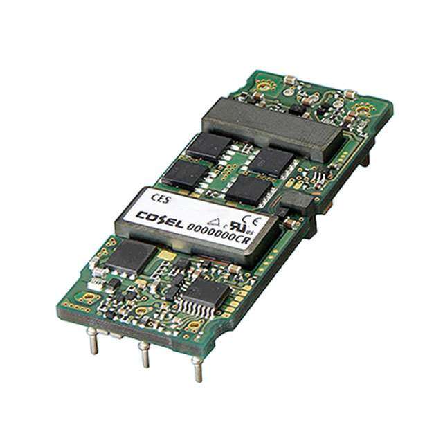
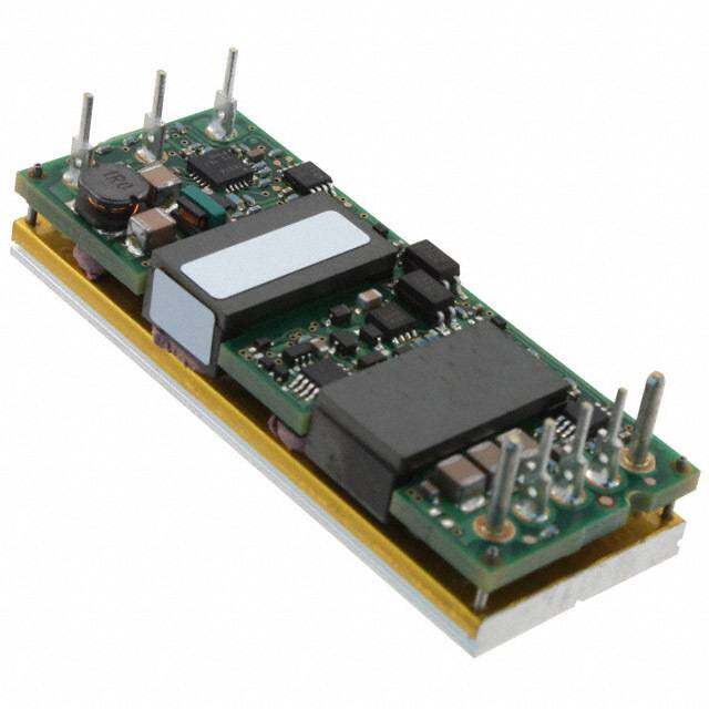
ICGOO电子元器件商城为您提供LSM2-T/30-D12R-C由Murata设计生产,在icgoo商城现货销售,并且可以通过原厂、代理商等渠道进行代购。 LSM2-T/30-D12R-C价格参考。MurataLSM2-T/30-D12R-C封装/规格:直流转换器, 非隔离 PoL 模块 DC/DC 转换器 1 输出 0.8 ~ 5 V 30A 8.3V - 13.2V 输入。您可以下载LSM2-T/30-D12R-C参考资料、Datasheet数据手册功能说明书,资料中有LSM2-T/30-D12R-C 详细功能的应用电路图电压和使用方法及教程。
Murata Power Solutions Inc. 的 LSM2-T/30-D12R-C 是一款直流-直流转换器模块,广泛应用于需要高效、稳定电源转换的工业和通信设备中。该模块具有宽输入电压范围、高效率和紧凑设计等特点,适用于以下典型应用场景:

1. 工业自动化设备:用于PLC、工业控制器、传感器和执行器等设备中的电源系统,提供稳定可靠的直流电源。

2. 通信设备:应用于基站、路由器、交换机等通信基础设施中,满足设备对电源高稳定性和高效率的要求。

3. 测试与测量仪器:为高精度测试设备提供干净、稳定的电源,确保测量数据的准确性。

4. 医疗设备:在非生命支持类医疗仪器中使用,如诊断设备、监测设备等,满足其对电源安全性和稳定性的要求。

5. 交通运输系统:适用于轨道交通、车载电子系统等场景,具备较强的抗干扰能力和环境适应性。

6. 嵌入式系统与服务器:作为嵌入式系统或服务器电源的一部分,为处理器、存储和其他模块提供所需电压。

该转换器支持表面贴装安装,适合自动化生产,广泛用于对空间和性能有较高要求的电子系统中。
| 参数 | 数值 |
| 产品目录 | |
| 描述 | CONV DC/DC 125W 30A 12V SMD |
| 产品分类 | DC DC Converters |
| 品牌 | Murata Power Solutions Inc |
| 数据手册 | |
| 产品图片 |
|
| 产品型号 | LSM2-T/30-D12R-C |
| rohs | 无铅 / 符合限制有害物质指令(RoHS)规范要求 |
| 产品系列 | LSM2 |
| 产品目录页面 | |
| 其它名称 | 811-1793-2 |
| 功率(W)-制造系列 | 125W |
| 功率(W)-最大值 | 125W |
| 包装 | 带卷 (TR) |
| 大小/尺寸 | 1.30" 长 x 0.53" 宽 x 0.34" 高(33.0mm x 13.5mm x 8.6mm) |
| 安装类型 | 表面贴装 |
| 封装/外壳 | 9-SMD 模块 |
| 工作温度 | -40°C ~ 85°C |
| 效率 | 94% |
| 标准包装 | 250 |
| 特性 | 远程开/关,OCP,SCP,UVLO |
| 电压-输入(最大值) | 13.2V |
| 电压-输入(最小值) | 8.3V |
| 电压-输出1 | 0.8 ~ 5 V |
| 电压-输出2 | - |
| 电压-输出3 | - |
| 电压-隔离 | - |
| 电流-输出(最大值) | 30A |
| 类型 | 非隔离 PoL 模块 |
| 输出数 | 1 |


- 商务部:美国ITC正式对集成电路等产品启动337调查
- 曝三星4nm工艺存在良率问题 高通将骁龙8 Gen1或转产台积电
- 太阳诱电将投资9.5亿元在常州建新厂生产MLCC 预计2023年完工
- 英特尔发布欧洲新工厂建设计划 深化IDM 2.0 战略
- 台积电先进制程称霸业界 有大客户加持明年业绩稳了
- 达到5530亿美元!SIA预计今年全球半导体销售额将创下新高
- 英特尔拟将自动驾驶子公司Mobileye上市 估值或超500亿美元
- 三星加码芯片和SET,合并消费电子和移动部门,撤换高东真等 CEO
- 三星电子宣布重大人事变动 还合并消费电子和移动部门
- 海关总署:前11个月进口集成电路产品价值2.52万亿元 增长14.8%


PDF Datasheet 数据手册内容提取
LSM2-T/30-D12 Series www.murata-ps.com DOSA-SMT, 30A POL DC/DC Converters Typical unit FEATURES DESCRIPTION Non-isolated Point-of-Load (POL) converter, ideal Today’s high performance CPU and programma- no additional external components required, for mixed voltage systems ble logic devices demand superior performance stable no-load operation, up to 10,000 µF output Optimized for CPUs, DSPs and programmable logic from their power source. The LSM2-T/30-D12 load capacitance and no reverse conduction. - FPGAs, ASICs series DC/DC converters offer up to 30 Amps System functions offer a remote On/Off 30 Amps maximum output current continuous output power with a user-selectable control, two additional ground pins (optional) User-selectable output voltage, 0.8Vdc to 5.0Vdc output of 0.8 to 3.6 Volts. 25 Amps output is and a load Sense input. These converters meet via trim resistor or voltage input available up to 5.0 Vout. This tiny converter is agency standards UL/EN 60950-1, CAN/CSA- Wide input range 6Vdc to 14Vdc (Vout <3.6V) ideal for applications with an input range of C22.2 60950-1, IEC 60950-1, 2nd edition, and 6 to 14 Volts DC. The pinout, trim system and EN55022/CISPR22 emissions characterization. Selectable phased start-up sequencing and tracking mechanical footprint is compatible with the DOSA The automated surface mount assembly is fully Excellent efficiency over output voltage range (www.dosapower.com) industry standard. compatible with RoHS (Reduction of Hazard- Two models available, with or without additional To ensure very high performance of powered ous Substances) construction and attachment. ground/thermal pads logic systems, the LSM2-T/30-D12 features low The LSM2-T/30-D12 mounts to its host carrier Fast settling, high di/dt slew rate, low output noise output noise, high slew rates (20 Amps/µSec.), board via reflow-soldered PCB pads. Extensive self protection plus 'hiccup' short circuit fast transient response (25 µSec settling) and The extraordinary efficiency means low heat auto recovery tight line and load regulation. Many logic devices and freedom from expensive, bulky heat sinks. A Meets full safety and emission certification require controlled start up and tracking capabili- wealth of protection features include input under- ties. The LSM2-T/30-D12 includes a Sequence/ voltage shutdown, output overcurrent current lim- Track function and prebias protection against iting, short circuit protection and overtemperature external startup voltages. Other features include shutdown/recycle. For full details go to www.murata-ps.com/rohs www.murata-ps.com/support MDC_LSM2_T30_D12 Series.E03∆ Page 1 of 12
LSM2-T/30-D12 Series DOSA-SMT, 30A POL DC/DC Converters PERFORMANCE SPECIFICATIONS SUMMARY AND ORDERING GUIDE Output Input Package R/N (mVp-p) Regulation (max.) Efficiency VOUT IOUT Power VIN Nom. Range IIN (Case/ Model Family (Volts) (Amps) (Watts) Typ. Max. Line Load (Volts) (Volts) (mA/A) Min. Typ. Pinout) LSM2-T/30-D12-C 0.8-5 30 125 15 25 ±0.2% ±0.4% 12 6-14 210/11.1 92.5% 94% C71, P72 LSM2-T/30-D12R-C To Be 0.8-5 30 125 15 25 ±0.2% ±0.4% 12 6-14 210/11.1 92.5% 94% C71, P72 LSM2-T/30-D12R-C-CIS 0.8-5 30 125 15 25 ±0.2% ±0.4% 12 6-14 210/11.1 92.5% 94% C71, P72 Typical @ Ta=+25°C. under nominal line voltage and full-load conditions unless noted. Nominal Nominal line voltage, no-load/full-load conditions. output is +5 Volts. LSM2-T/30-D12 efficiencies are shown at Vout = 5 Volts. Ripple/Noise (R/N) is tested/specified over a 5 Hz to 20 MHz bandwidth and may be reduced by Iout max. is 30 Amps with Vout = 0.8 to 3.6 Volts. With Vout >3.6 Volts, Iout max. is 25 Amps. adding external filtering. R/N is shown at Vout <= 2.5 Volts. ➆ If Vout >3.63V, input range is 7-14V. These devices have no minimum load requirements and will regulate under no-load conditions. ➇ LSM2-T/30-D12R-C-CIS models use a 100KΩ resistor between the gate and source of the internal Regulation specifications describe the output voltage deviation as the line voltage or load is varied On/Off (Enable) FET controlling the PWM. from its nominal/midpoint value to either extreme. PART NUMBER STRUCTURE L SM2 - T / 30-D12 R-C Output Configuration: RoHS6 Hazardous Substance Compliant L = Unipolar (does not claim EU RoHS exemption 7b–lead in solder) Low Voltage Additional Grounds: Blank = Omitted Non-Isolated SMT R = Installed Nominal Output Voltage: Input Voltage Range: 0.8-5.0 Volts D12 = 6-14 Volts (12V nominal) See note 7 above. Maximum Rated Output Current in Amps CONNECTION DIAGRAM +INPUT +OUTPUT Additional * +SENSE ground/thermal pads COMMON COMMON VCC CURRENT PWM SENSE ON/OFF CONTROLLER CONTROL VTRACK/ REFERENCE & SEQUENCE ERROR AMP VOUT INPUT TRIM *One phase of two is shown. Typical topology is shown. www.murata-ps.com/support MDC_LSM2_T30_D12 Series.E03∆ Page 2 of 12
LSM2-T/30-D12 Series DOSA-SMT, 30A POL DC/DC Converters MECHANICAL SPECIFICATIONS Case C71 PIN #1 THIS SMT contacts: copper alloy with CORNER (FARSIDE) 5μ" Au (min.) over 50μ" Ni (min.) 13.5 TOP INPUT/OUTPUT CONNECTIONS P72 0.53 VIEW Pad Function 1 On/Off Control ISOMETRIC 2 +Input 33.0 VIEW 3 Sequence/Track In 1.30 PIN #1 4 Common SIDE END 5 +Output VIEW VIEW 6 Trim 9.1 0.36 7 Sense In MTG PLANE 9* Common 0.020 MIN 2.03±0.13 10* Common BETWEEN MTG PLANE 0.080±0.005 Pins 9 & 10 PRESENT * AND COMPONENTS 1.57±0.20 REF ONLY ON 'R' OPTION 0.062±0.008 CONTACTS TYP ALL PINS COPLANAR WITHIN 4 MILS 4 EQ SP @ 0.190 [4.83] EACH 08..37465 Dimensions are in inches (mm) shown for ref. only. EQUALS 0.760 [19.30] 4.83 Component locations Third Angle Projection 0.190 BOTTOM are typical. REF VIEW 3 4 5 6 7 3.05 0.120 Tolerances (unless otherwise specified): 10.04.3902 10 9 1.91 ..XXXX X± ± 0 .00.20 1(00. 5(0).25) 0.075 Angles ± 2˚ 2 1 Components are shown for reference only. 1.27 0.0502 .90 0.69 219.1.9770 1.22 30.581.20429.901.177 26.851.057 22.020.867 17.200.677 12.370.487 7.54 0.297 0 0.114 0.027 0.048 1.47 2.16 0.64 0.058 0.085 DIMENSIONS ARE IN INCHES [mm] 0.025 TOLERANCES: 0 2 1 0 23 PPLLAACCEE 00..0021 0 ANGLES: 1 2.26 10 9 3.05 14.0 0.089 2.41 * 0.120 0.55 COMPONENTS SHOWN ARE FOR REFERENCE ONLY 0.095 3 4 5 6 7 10.29 REF 0.405 MATERIAL: SMT PINS: COPPER ALLOY FINISH: (ALL PINS) 0.140 [3.56] x 3.56 2.41 0.095 [2.41] x GOLD (5u"MIN) OVER NICKEL (50u" MIN) 0.095 [2.41] 0.140 0.095 0.082 [2.08] PADS PADS FOR PINS REF REF FOR PINS 9 & 10 1 THRU 7 (7 PLS) (OPTIONAL GNDS) 33.5 1.32 Additional Ground/Thermal Pads (“R” models) To realize the additional current and thermal capacity of “R” models, you must have a substantial area of several square inches of copper etch flow- The LSM2-T/30-D12 is optionally available with two additional ground soldered to these pads and sufficient feed-throughs or other means of con- pads for increased current handling and better heat transfer. These are ducting current. The “R” pads and the standard pads 1 and 2 are in parallel. indicated with the “R” designator in the model number, LSM2-T/30-D12R-C. MPS recommends that users lay out their PC boards to accept these two If your application uses a standard DOSA pad layout and you cannot connect pads for larger current applications. Please note that the Derating curves for to these ground pads, order model LSM2-T/30-D12-C without the “R” designa- the “R” models accept higher temperature and greater current limits than tor. Please observe the lower Derating curves for standard, “non-R” models. units without the additional pads. www.murata-ps.com/support MDC_LSM2_T30_D12 Series.E03∆ Page 3 of 12
LSM2-T/30-D12 Series DOSA-SMT, 30A POL DC/DC Converters SHIPPING SPECIFICATIONS FEED (UNWIND) PICK-UP NOZZLE LOCATION DIRECTION ------ ( 6mm MAX) PIN #1 TYP 2.0 (ORIENTATION) 4.00 9.7 0.08 0.157 0.38 TYP 20.3 0.80 40.4 44.0 1.59 1.73 35.1 REF WIDTH 1.38 24.00 0.945 PITCH Dimensions are in inches (mm) shown for ref. only. Third Angle Projection TOP COVER TAPE Tolerances (unless otherwise specified): .XX ± 0.02 (0.5) .XXX ± 0.010 (0.25) Angles ± 2˚ Components are shown for reference only. PIN #1 THIS CORNER FEED (UNWIND) (FAR SIDE) DIRECTION 44.0 ------- 1.73 REF 16.5 PICKUP NOZZLE 0.65 LOCATION ( 6.5-7.5mm) 330.2 13.00 101.6 4.00 13.00 6.7 (CORE) 0.512 0.27 REEL INFORMATION PICK & PLACE PICKUP (P/U) (250 UNITS PER REEL) www.murata-ps.com/support MDC_LSM2_T30_D12 Series.E03∆ Page 4 of 12
LSM2-T/30-D12 Series DOSA-SMT, 30A POL DC/DC Converters Performance and Functional Specifications See Note 1 Input Dynamic Characteristics Input Voltage Range See Ordering Guide Dynamic Load Response 60 µSec to within ±2% of final value Isolation Not isolated. Input and output (50-100-50% load step, di/dt=20A/µSec) Commons are internally connected. Start-Up Time 10 mSec for Vout=nominal Start-Up Voltage 5.6 Volts (Vin on to Vout regulated or On/Off to Vout) Undervoltage Shutdown 5 Volts Switching Frequency 430 KHz Overvoltage Shutdown None Environmental Reflected (Back) Ripple Current (Note 2) 50 mA pk-pk Calculated MTBF (4) 3,917,077 Hours Internal Input Filter Type Capacitive Operating Temperature Range -40 to +85°C. (Note 9) Reverse Polarity Protection None, install external fuse. With derating See Derating Curves (Note 12) Recommended External Fuse 35 Amps, fast blow Storage Temperature Range -55 to +125°C. Input Current: Thermal Protection/Shutdown +115°Celsius Full Load Conditions See Ordering Guide MSL Rating 2a Inrush Transient 0.4 A2Sec. Relative Humidity to 85%/+85°C, non-condensing Shutdown Mode (Off, UV, OT) 5 mA Output Short Circuit 60 mA Physical Low Line (Vin=Vmin, 5Vout) 18.9 Amps Outline Dimensions See Mechanical Specifications Remote On/Off Control (Note 5) Weight 0.28 ounces (7.8 grams) Negative Logic (No model suffix) ON = Open pin or 0 to +0.55 V max. OFF = +3.0V min. to +Vin max. Electromagnetic Interference Meets EN55022/CISPR22 Current 1.3 mA max. (conducted and radiated) (may need external filter) Safety Meets UL/cUL 60950-1, IEC/EN 60950-1, Output 2nd edition Minimum Loading No minimum load Absolute Maximum Ratings Accuracy (50% load) ±1.5 % of Vnominal Input Voltage (Continuous or transient) +15 Volts Voltage Adjustment Range (Note 13) See Ordering Guide Overvoltage Protection (Note 20) None On/Off Control (negative logic) Zero Volts min. to +Vin max. Input Reverse Polarity Protection None, install external fuse. Temperature Coefficient ±0.01% per οC of Vout range Output Current (Note 7) Current-limited. Devices can withstand Ripple/Noise (20 MHz bandwidth) See Ordering Guide and Note 8 sustained short circuit without damage. Line/Load Regulation (See Tech. Notes) See Ordering Guide and Note 10 Storage Temperature -55 to +125°C. Efficiency See Ordering Guide Lead Temperature See soldering guidelines Maximum Capacitive Loading (Note 15) Cap-ESR=0.001 to 0.01 Ohms 5,000 µF Absolute maximums are stress ratings. Exposure of devices to greater than any of these conditions may adversely affect long-term reliability. Proper operation under conditions other than those listed Cap-ESR >0.01 Ohms 10,000 µF in the Performance/Functional Specifications Table is neither implied nor recommended. Current Limit Inception (Note 19) 48 Amps (cold startup) (98% of Vout setting) 42 Amps (after warm up) Specification Notes: (1) Specifications are typical at +25°C, Vin=nominal (+12V), Vout=nominal (+5V), full load, external Short Circuit Mode (Note 6) caps and natural convection unless otherwise indicated. Tests at full power should supply Short Circuit Current Output 600 mA substantial forced airflow. All models are tested and specified with external 0.1µF and 10 µF paralleled ceramic/tantalum Protection Method Hiccup autorecovery upon overload output capacitors and a 22 µF external input capacitor. All capacitors are low ESR types. These removal. (Note 17) capacitors are necessary to accommodate our test equipment and may not be required to achieve specified performance in your applications. All models are stable and regulate within spec under Short Circuit Duration Continuous, no damage (output shorted no-load conditions. to ground) (2) Input Back Ripple Current is tested and specified over a 5 Hz to 20 MHz bandwidth. Input filter- Prebias Startup (Note 16) Converter will start up if the external ing is Cin=2 x 100 µF tantalum, Cbus=1000 µF electrolytic, Lbus=1 µH. output voltage is less than Vnominal. (3) Note that Maximum Power Derating curves indicate an average current at nominal input voltage. At higher temperatures and/or lower airflow, the DC/DC converter will tolerate brief full Sequencing current outputs if the total RMS current over time does not exceed the Derating curve. Slew Rate 2V per millisecond max. (4) Mean Time Before Failure is calculated using the Telcordia (Belcore) SR-332 Method 1, Case 3, ground fixed conditions, Tpcboard=+25°C, full output load, natural air convection. Startup delay until sequence start 10 milliseconds min. (5) The On/Off Control may be driven with external logic or by applying appropriate external volt- Tracking accuracy, rising input Vout=±100 mV of Sequence In ages which are referenced to -Input Common. The On/Off Control Input should use either an open collector/open drain transistor or logic gate which does not exceed +Vin. Tracking accuracy, falling input Vout=±200 mV of Sequence In (6) Short circuit shutdown begins when the output voltage degrades approximately 2% from the selected setting. Remote Sense to Vout 0.5V max. (Note 7) www.murata-ps.com/support MDC_LSM2_T30_D12 Series.E03∆ Page 5 of 12
LSM2-T/30-D12 Series DOSA-SMT, 30A POL DC/DC Converters Specification Notes continued: Resistor Trim Equation (7) If Sense is connected remotely at the load, up to 0.5 Volts difference is allowed between the Sense and +Vout pins to compensate for ohmic voltage drop in the power lines. A larger volt- age drop may cause the converter to exceed maximum power dissipation. 1200 (8) Output noise may be further reduced by adding an external filter. See I/O Filtering and Noise Reduc- RTRIM (in Ohms) = --------------------- -100 tion. VOUT – 0.8 (9) All models are fully operational and meet published specifications, including “cold start” at –40° C. (10)Regulation specifications describe the deviation as the line input voltage or output load current is varied from a nominal midpoint value to either extreme. The fixed trim resistors to set the output voltage are: (11)Other input or output voltage ranges will be reviewed under scheduled quantity special order. (12)Maximum continuous power requires that all on-board components not exceed +128°C pack- Vout 0.8V. 1.0V. 1.2V. 1.5V. 1.8V. age temperature. 1.614 (13)Do not exceed maximum power specifications when adjusting the output trim. Rtrim (Ohms) Open 5.90 KΩ 2.90 KΩ 1.10 KΩ KΩ (14)The “R” option includes extra ground pads. These pads offer two important features. In addition to carrying extra current, they also help dissipate additional heat. MPS strongly recommends Vout 2.0V. 2.5V. 3.3V. 5.0V. soldering the “R” pads to a thick ground plane with sizable area. The Operating Temperature 185.71 specification listed above assumes that these additional ground pads are connected to Rtrim (Ohms) 0.90 KΩ 605 Ω 380 Ω Ω a substantial ground plane below the converter ( at least several square inches). (15)The maximum output capacitive loads depend on the the Equivalent Series Resistance (ESR) of the external output capacitor. Larger caps will reduce output noise but may slow transient response. (16)Do not use Pre-bias startup and sequencing together. If you do not use the track function, leave the seq/trk pin open. (17)After short circuit shutdown, if the load is partially removed such that the load still exceeds the overcurrent (OC) detection, the converter will remain in hiccup restart mode. (18)Output current limiting is disabled at start up to avoid overcurrent shutdown while charging external bypass capacitors. Output Adjustments Voltage Reference, The LSM2-T/30-D12 series includes a special output voltage trimming fea- ture which is fully compatible with competitive units. The output voltage may be varied using a single trim resistor from the Trim Input to Power Common. Use a precision, low-tempco resistor (±100 ppm/οC) mounted close to Figure 2. Voltage Trim Connections the converter with short leads. Be aware that the voltage accuracy is ±1.5% (typical) therefore adjust this resistance to achieve your desired output. Voltage Trim The LSM2 Series may also be trimmed using an external low-noise voltage applied between the Trim input and Output Common. Be aware that the inter- nal “load” impedance looking into Trim pin is below 1000 Ohms and includes factors from the output voltage. Therefore, use a low impedance source resistance in your external voltage reference. The fixed trim voltages to set the output voltage are: Vout (typ.) 0.80V. 1.0V. 1.2V. 1.5V. 1.8V. Vtrim (Volts) Open 0.731V. 0.719V. 0.7V. 0.682V Figure 1. Trim Resistor Connections Vout (typ.) 2.0 V. 2.5V. 3.3V. 5.0V. Vtrim (Volts) 0.669V. 0.638V. 0.589V. 0.484V. Vtrim = 0.7434 – [(((Vout – 0.7434) ÷ 1620) – 0.000035) x 100] where Vout = desired voltage Soldering Guidelines Murata Power Solutions recommends the specifications below when installing these converters. These specifications vary depending on the solder type. Exceeding these specifica- tions may cause damage to the product. Your production environment may differ therefore please thoroughly review these guidelines with your process engineers. Reflow Solder Operations for surface-mount products (SMT) For Sn/Ag/Cu based solders: For Sn/Pb based solders: Preheat Temperature Less than 1 ºC. per second Preheat Temperature Less than 1 ºC. per second Time over Liquidus 45 to 75 seconds Time over Liquidus 60 to 75 seconds Maximum Peak Temperature 260 ºC. Maximum Peak Temperature 235 ºC. Cooling Rate Less than 3 ºC. per second Cooling Rate Less than 3 ºC. per second www.murata-ps.com/support MDC_LSM2_T30_D12 Series.E03∆ Page 6 of 12
LSM2-T/30-D12 Series DOSA-SMT, 30A POL DC/DC Converters PERFORMANCE DATA: OUTPUT VOLTAGE = 5 VOLTS Efficiency vs. Line Voltage and Load Current @ +25°C Output Ripple & Noise (Vin = 12 V, Iout = 20 A, Cout = 10µF || 1µF, ’scope = 20 MHz BW) Vertical = 20 mV/div., Sweep = 1µS/div. 98 93 88 83 VIN = 14 V %) VIN = 12 V Efficiency ( 7738 VIN = 7 V 68 63 58 1 2.66 4.31 5.97 7.62 9.28 10.9 12.6 14.2 15.9 17.6 19.2 20.9 22.5 24.2 Load Current (Amps) LSM2-T/30-D12R Maximum Current Temperature Derating at Sea Level Power-On Startup (Vin = 12 V, Iout = 25 A) (Vin= 12V, Transverse Airflow). Extra ground pads installed. Ch2 = 20 A/div. 31.00 30.00 29.00 300 LFM 400 LFM 28.00 500 LFM 27.00 26.00 25.00 24.00 mps)23.00 Output Current (A111222789012......000000000000Natural Co12n00v00e cLLtFFioMMn 16.00 15.00 14.00 13.00 12.00 20 25 30 35 40 45 50 55 60 65 70 75 80 85 90 Ambient Temperature (°C) LSM2-T/30-D12 Maximum Current Temperature Derating at Sea Level StepLoad Transient Response (Vin = 12 V, 0-15A-0) (Vin= 12V, Transverse Airflow). No extra ground pads. 31.00 30.00 29.00 28.00 300 LFM 27.00 400 LFM 26.00 500 LFM 25.00 Amps) 2234..0000 urrent ( 222012...000000 put C 1189..0000 Out 17.00 16.00Natural Convection 15.00 100 LFM 14.00 200 LFM 13.00 12.00 11.00 20 25 30 35 40 45 50 55 60 65 70 75 80 85 90 Ambient Temperature (°C) www.murata-ps.com/support MDC_LSM2_T30_D12 Series.E03∆ Page 7 of 12
LSM2-T/30-D12 Series DOSA-SMT, 30A POL DC/DC Converters PERFORMANCE DATA: OUTPUT VOLTAGE = 3.3 VOLTS Efficiency vs. Line Voltage and Load Current (Vin = 12V) @ +25°C Output Ripple & Noise (Vin = 12 V, Iout = 20 A, Cout = 10µF || 1µF, ’scope = 20 MHz BW) Vertical = 20 mV/div., Sweep = 1µS/div. 93 88 VIN = 14 V %) 83 VIN = 12 V ncy ( 78 VIN = 6 V Efficie 73 68 63 58 1 2 3 4 5 6 7 8 9 101112131415161718192021222324252627282930 Output Current (Amps) LSM2-T/30-D12R Maximum Current Temperature Derating at Sea Level Power-On Startup (Vin = 12 V, Iout = 25 A) (Vin= 12V, Transverse Airflow). Extra ground pads installed. 31.00 30.00 300 LFM 29.00 400 LFM 28.00 27.00 26.00 25.00 mps) 2234..0000 A Output Current ( 1122289012.....0000000000 Natural Co12n00v00e cLLtFFioMMn 17.00 16.00 15.00 14.00 13.00 12.00 20 25 30 35 40 45 50 55 60 65 70 75 80 85 90 Ambient Temperature (°C) LSM2-T/30-D12 Maximum Current Temperature Derating at Sea Level StepLoad Transient Response (Vin = 12 V, 0-15A-0) (Vin= 12V, Transverse Airflow). No extra ground pads. 31.00 30.00 29.00 400 LFM 500 LFM 28.00 27.00 26.00 25.00 Amps) 2234..0000 urrent ( 222012...000000 C Output 111789...000000 Natural Co123n000v000e cLLLtFFFioMMMn 16.00 15.00 14.00 13.00 12.00 20 25 30 35 40 45 50 55 60 65 70 75 80 85 90 Ambient Temperature (°C) www.murata-ps.com/support MDC_LSM2_T30_D12 Series.E03∆ Page 8 of 12
LSM2-T/30-D12 Series DOSA-SMT, 30A POL DC/DC Converters PERFORMANCE DATA: OUTPUT VOLTAGE = 2.5 VOLTS Efficiency vs. Line Voltage and Load Current (Vin = 12V) @ +25°C Output Ripple & Noise (Vin = 12 V, Iout = 20 A, Cout = 10µF || 1µF, ’scope = 20 MHz BW) Vertical = 20 mV/div., Sweep = 1µS/div. 93 88 83 VIN = 14 V VIN = 12 V Efficiency (%) 7738 VIN = 6 V 68 63 58 1 2 3 4 5 6 7 8 9 10 11 12 13 14 15 16 17 18 19 20 21 22 23 24 25 26 27 28 29 30 Output Current (Amps) LSM2-T/30-D12R Maximum Current Temperature Derating at Sea Level (Vin= 12V, Transverse Airflow). Extra ground pads installed. 31.00 30.00 300 LFM 29.00 400 LFM 28.00 27.00 26.00 mps) 25.00 A 24.00 Current ( 2223..0000 Output 2201..0000 Natural Co12n00v00e cLLtFFioMMn 19.00 18.00 17.00 16.00 15.00 20 25 30 35 40 45 50 55 60 65 70 75 80 85 90 Ambient Temperature (°C) LSM2-T/30-D12 Maximum Current Temperature Derating at Sea Level StepLoad Transient Response (Vin = 12 V, 0-15A-0) (Vin= 12V, Transverse Airflow). No extra ground pads. 31.00 30.00 29.00 28.00 27.00 300 LFM 26.00 400 LFM 25.00 mps) 24.00 A 23.00 utput Current ( 12229012....00000000 O 18.00 Natural Convection 17.00 120000 LLFFMM 16.00 15.00 14.00 13.00 20 25 30 35 40 45 50 55 60 65 70 75 80 85 90 Ambient Temperature (°C) www.murata-ps.com/support MDC_LSM2_T30_D12 Series.E03∆ Page 9 of 12
LSM2-T/30-D12 Series DOSA-SMT, 30A POL DC/DC Converters PERFORMANCE DATA: OUTPUT VOLTAGE = 1.8 VOLTS Efficiency vs. Line Voltage and Load Current @ +25°C Output Ripple & Noise (Vin = 12 V, Iout = 20 A, Cout = 10µF || 1µF, ’scope = 20 MHz BW) Vertical = 10 mV/div., Sweep = 1µS/div. 91 86 81 Efficiency (%) 7716 VVVIIINNN === 611 24V VV 66 61 56 1 2 3 4 5 6 7 8 9 101112131415161718192021222324252627282930 Load Current (Amps) LSM2-T/30-D12R Maximum Current Temperature Derating at Sea Level Power-On Startup (Vin = 12 V, Iout = 25 A) (Vin= 12V, Transverse Airflow). Extra ground pads installed. 31.00 30.00 300 LFM 29.00 400 LFM 28.00 27.00 26.00 Output Current (Amps) 2222212345.....0000000000 Natural Co12n00v00e cLLtFFioMMn 20.00 19.00 18.00 17.00 20 25 30 35 40 45 50 55 60 65 70 75 80 85 90 Ambient Temperature (°C) LSM2-T/30-D12 Maximum Current Temperature Derating at Sea Level StepLoad Transient Response (Vin = 12 V, 0-15A-0) (Vin= 12V, Transverse Airflow). No extra ground pads. 31.00 30.00 300 LFM 29.00 400 LFM 28.00 27.00 26.00 25.00 mps) 24.00 A 23.00 utput Current ( 12229012....00000000Natural Co1n0v0e cLtFioMn O 18.00 200 LFM 17.00 16.00 15.00 14.00 13.00 20 25 30 35 40 45 50 55 60 65 70 75 80 85 90 Ambient Temperature (°C) www.murata-ps.com/support MDC_LSM2_T30_D12 Series.E03∆ Page 10 of 12
LSM2-T/30-D12 Series DOSA-SMT, 30A POL DC/DC Converters PERFORMANCE DATA: OUTPUT VOLTAGE = 1.2 VOLTS Efficiency vs. Line Voltage and Load Current @ +25°C (Vin = 12V) Output Ripple & Noise (Vin = 12 V, Iout = 30 A, Cout = 10µF || 1µF, ’scope BW = 20 MHz) 89 84 79 VIN = 6 V VIN = 12 V VIN = 14 V 74 Efficiency (%) 69 64 59 54 49 1 2 3 4 5 6 7 8 9 10 11 12 13 14 15 16 17 18 19 20 21 22 23 24 25 26 27 28 29 30 Output Current (Amps) LSM2-T/30-D12R Maximum Current Temperature Derating Power-On Startup (Vin = 12 V, Iout = 30 A) (Vin= 12V, Transverse Airflow). Extra ground pads installed. 31.00 30.00 300 LFM 29.00 400 LFM 28.00 mps)2267..0000 Output Current (A222222012345......000000000000 Natural Co12n00v00e cLLtFFioMMn 19.00 18.00 17.00 16.00 20 25 30 35 40 45 50 55 60 65 70 75 80 85 90 Ambient Temperature (°C) StepLoad Transient Response (Vin = 12 V, 0-15A-0) www.murata-ps.com/support MDC_LSM2_T30_D12 Series.E03∆ Page 11 of 12
LSM2-T/30-D12 Series DOSA-SMT, 30A POL DC/DC Converters PERFORMANCE DATA: OUTPUT VOLTAGE = 0.8 VOLTS Efficiency vs. Line Voltage and Load Current @ +25°C (Vin = 12V) Output Ripple & Noise (Vin = 12 V, Iout = 30 A, Cout = 10µF || 1µF, ’scope BW = 20 MHz) 87 82 77 72 VVIINN == 1124 VV VIN = 6 V Efficiency (%) 6627 57 52 47 42 1 2 3 4 5 6 7 8 9 10 11 12 13 14 15 16 17 18 19 20 21 22 23 24 25 26 27 28 29 30 Output Current (Amps) LSM2-T/30-D12R Maximum Current Temperature Derating Power-On Startup (Vin = 12 V, Iout = 30 A) (Vin= 12V, Transverse Airflow). Extra ground pads installed. 31.00 30.00 300 LFM 29.00 400 LFM 28.00 mps) 2267..0000 Output Current (A 222222012345......000000000000 Natural Co12n00v00e cLLtFFioMMn 19.00 18.00 17.00 16.00 20 25 30 35 40 45 50 55 60 65 70 75 80 85 90 Ambient Temperature (°C) StepLoad Transient Response (Vin = 12 V, 0-15A-0) This product is subject to the following operating requirements Murata Power Solutions, Inc. and the Life and Safety Critical Application Sales Policy: 129 Flanders Road, Westborough, MA 01581 U.S.A. Refer to: http://www.murata-ps.com/requirements/ ISO 9001 and 14001 REGISTERED Murata Power Solutions, Inc. makes no representation that the use of its products in the circuits described herein, or the use of other technical information contained herein, will not infringe upon existing or future patent rights. The descriptions contained herein do not imply the granting of licenses to make, use, or sell equipment constructed in accordance therewith. Specifications are subject to change witho ut n oti ce. © 2018 Murata Power Solutions, Inc. www.murata-ps.com/support MDC_LSM2_T30_D12 Series.E03∆ Page 12 of 12