ICGOO在线商城 > 电感器,线圈,扼流圈 > 固定值电感器 > LQH32PN220MN0L
 Datasheet下载
- 型号: LQH32PN220MN0L
- 制造商: Murata
- 库位|库存: xxxx|xxxx
- 要求:
| 数量阶梯 | 香港交货 | 国内含税 |
| +xxxx | $xxxx | ¥xxxx |
查看当月历史价格
查看今年历史价格
LQH32PN220MN0L产品简介:
ICGOO电子元器件商城为您提供LQH32PN220MN0L由Murata设计生产,在icgoo商城现货销售,并且可以通过原厂、代理商等渠道进行代购。 LQH32PN220MN0L价格参考¥1.55-¥1.93。MurataLQH32PN220MN0L封装/规格:固定值电感器, 22µH Shielded Wirewound Inductor 450mA 972 mOhm Max Nonstandard。您可以下载LQH32PN220MN0L参考资料、Datasheet数据手册功能说明书,资料中有LQH32PN220MN0L 详细功能的应用电路图电压和使用方法及教程。
Murata Electronics North America的LQH32PN220MN0L是一款固定值电感器,常用于需要高精度和稳定性的电子电路中。该型号电感器属于小型贴片电感,具有低直流电阻、高饱和电流和良好的温度稳定性,适用于电源管理电路、DC-DC转换器、电压调节模块(VRM)等场合。

它在便携式电子产品如智能手机、平板电脑和笔记本电脑中广泛应用,用于提高电源效率和稳定性。此外,该电感器也适用于通信设备、工业控制系统以及汽车电子系统中的电源滤波和噪声抑制。

由于其优异的高频特性,LQH32PN220MN0L也可用于射频(RF)电路中的匹配网络和滤波电路,帮助提升信号质量和系统性能。其紧凑的设计使其适合高密度PCB布局,满足现代电子产品对小型化和高性能的双重需求。
| 参数 | 数值 |
| 产品目录 | |
| DC电阻(DCR) | 810 毫欧 |
| 描述 | INDUCTOR POWER 22UH 450MA 1210固定电感器 1210 22uH 20% |
| 产品分类 | |
| 品牌 | Murata Electronics North America |
| 产品手册 | |
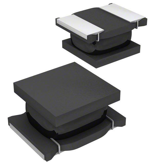
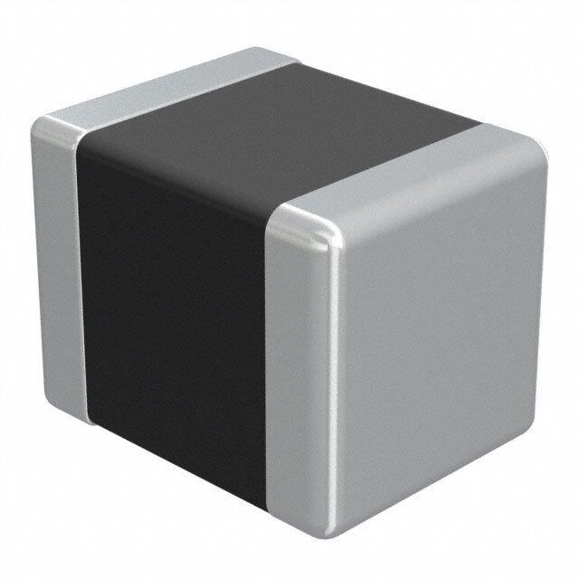
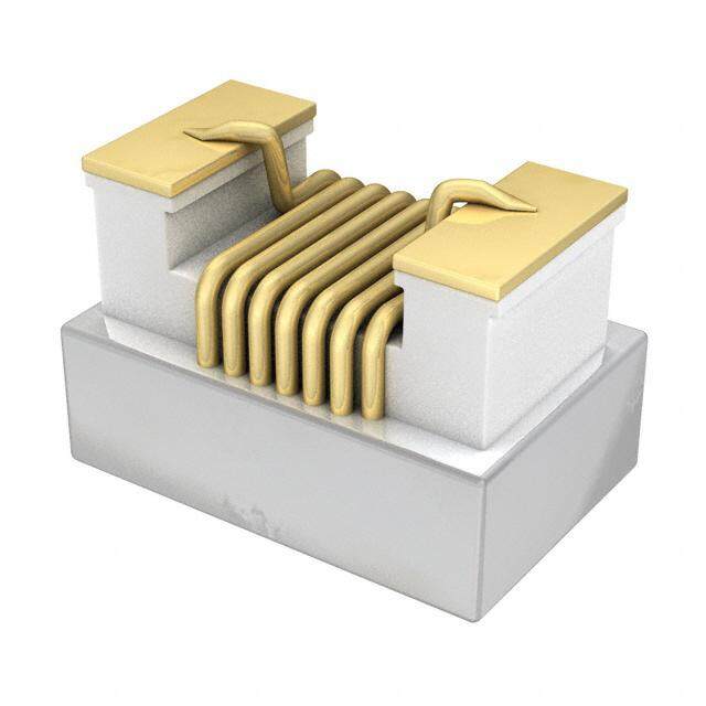
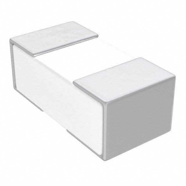
| 产品图片 |
|
| rohs | 符合RoHS无铅 / 符合限制有害物质指令(RoHS)规范要求 |
| 产品系列 | 固定电感器,Murata Electronics LQH32PN220MN0LLQH32P_N0 |
| 数据手册 | |
| 产品型号 | LQH32PN220MN0L |
| 不同频率时的Q值 | - |
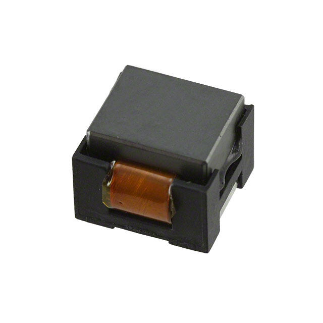
| 产品目录绘图 |
|
| 产品目录页面 | |
| 产品种类 | 固定电感器 |
| 供应商器件封装 | 1210 |
| 其它名称 | 490-5341-6 |
| 包装 | Digi-Reel® |
| 单位重量 | 44 mg |
| 商标 | Murata Electronics |
| 外壳宽度 | 2.5 mm |
| 外壳长度 | 3.2 mm |
| 外壳高度 | 1.55 mm |
| 大小/尺寸 | 0.126" 长 x 0.098" 宽(3.20mm x 2.50mm) |
| 安装类型 | 表面贴装 |
| 容差 | ±20% |
| 封装 | Reel |
| 封装/外壳 | 1210(3225 公制) |
| 封装/箱体 | 1210 (3225 metric) |
| 屏蔽 | 屏蔽 |
| 工作温度 | -40°C ~ 85°C |
| 工作温度范围 | - 40 C to + 85 C |
| 工厂包装数量 | 2000 |
| 最大直流电流 | 500 mA |
| 最大直流电阻 | 972 mOhms |
| 材料-磁芯 | - |
| 标准包装 | 1 |
| 电感 | 22µH |
| 电流-饱和值 | - |
| 端接类型 | SMD/SMT |
| 类型 | 绕线 |
| 自谐振频率 | 20 MHz |
| 频率-测试 | 1MHz |
| 频率-自谐振 | 20MHz |
| 额定电流 | 450mA |
| 高度-安装(最大值) | 0.067"(1.70mm) |


- 商务部:美国ITC正式对集成电路等产品启动337调查
- 曝三星4nm工艺存在良率问题 高通将骁龙8 Gen1或转产台积电
- 太阳诱电将投资9.5亿元在常州建新厂生产MLCC 预计2023年完工
- 英特尔发布欧洲新工厂建设计划 深化IDM 2.0 战略
- 台积电先进制程称霸业界 有大客户加持明年业绩稳了
- 达到5530亿美元!SIA预计今年全球半导体销售额将创下新高
- 英特尔拟将自动驾驶子公司Mobileye上市 估值或超500亿美元
- 三星加码芯片和SET,合并消费电子和移动部门,撤换高东真等 CEO
- 三星电子宣布重大人事变动 还合并消费电子和移动部门
- 海关总署:前11个月进口集成电路产品价值2.52万亿元 增长14.8%


PDF Datasheet 数据手册内容提取
Inductor for Power Lines (Power Inductor) Soldering and Mounting 1. Standard Land Pattern Dimensions A high Q value is achieved when the PCB electrode land pattern is designed so that it does not project beyond the chip inductor (chip coil) electrode. Land Pattern + Solder Resist Land Pattern Solder Resist (in mm) Series Standard Land Dimensions LQM18F/18P Part Number a b c LQM21D/21F/21P LQM2MP LQM18F Flow 0.7 2.2-2.6 0.7 LQM2HP /18P Reflow 1.8-2.0 LQM31P LQM21D/21F/21P 1.2 3.0-4.0 1.0 LQM32P LQM2MP 0.8 2.4 1.8 LQH2MC LQM2HP 1.6 3.0 1.5 LQH31C LQM31P 2.0 4.2-5.2 1.2 LQH32P LQM32P 1.9 3.6 2.7 LQH44P LQH5BP c LQH2MC 0.8 2.6 1.0 LQH55D/66S LQH31C 1.0 4.5 1.5 LQW15C_00 a LQH32P 1.3 3.8 2.0 LQW15C_10 b LQH44P 1.3 4.4 3.0 LQW18C LQH5BP 1.8 5.5 4.1 LQH55D/66S 2.0 8.0 3.5 LQW15C_00 0.4 1.4 0.6 LQW15C_10 0.4 1.4 0.66 LQW18C 0.7 2.2 1.0 LQH2HP 4 1. 0.8 3.0 LQH32C 5.5 0 0 2. 1. 1.0 1.3 1.0 LQH3NP 2.4 0.7 0.7 75 0.45 0.45 0. 3 3. 75 1.15 1.0 1.15 0. 3.3 LQH43C 7.5 LQH43P 05 3.1. 1.5 1.5 1.5 LQH55P 45˚ 2.9 6.7 1.6 Attention should be paid to potential magnetic coupling effects when using the inductor (coil) as a resonator. Continued on the following page.
Inductor for Power Lines (Power Inductor) Soldering and Mounting 2. Standard Soldering Conditions (1) Soldering method Solder: Use Sn-3.0Ag-0.5Cu solder. Chip inductor (Chip coils) can be flow or reflow soldered. Flux: Use rosin-based flux, but not strongly acidic flux (with Please contact Murata regarding other soldering chlorine content exceeding 0.2wt%). methods. Do not use water-soluble flux. As for LQH2MC/2HP/3NP/32P/44P/5BP/55D/55P/66S, The flux used for LQW15C/18C series should use the LQM32P, LQW15C/18C series, please use reflow rosin-based flux that includes middle activator soldering. equivalent to 0.06wt% to 0.1wt% chlorine. For additional mounting methods, please contact Murata. (2) Soldering profile "Flow Soldering profile (Sn-3.0Ag-0.5Cu solder) ure (°C) TT32 t2 erat T1 Heating Limit Profile p m Standard Profile e T Pre-heating time (s) t1 Standard Profile Limit Profile Pre-heating Series Heating Cycle Heating Cycle Temp. (T1) Time. (t1) Temp. (T2) Time. (t2) of flow Temp. (T3) Time. (t2) of flow LQM18F/18P LQM21D/21F/21P/2MP/2HP 2 times 2 times 150°C 60s min. 250°C 4 to 6s 265±3°C 5s max. LQM31P max. max. LQH31C LQH32C 2 times 150°C 60s min. 250°C 4 to 6s 265±3°C 5s max. 1 times LQH43C/43P max. "Reflow Soldering profile (Sn-3.0Ag-0.5Cu solder) T4 T2 C) T3 e (°180 T1 atur150 er Limit Profile p m Pre-heating t1 e Standard Profile T t2 90±30s time (s) Standard Profile Limit Profile Series Heating Peak Cycle Heating Peak Cycle temperature temperature Temp. (T1) Time. (t1) (T2) of reflow Temp. (T3) Time. (t2) (T4) of reflow LQM18F/18P LQM21D/21F/21P/2MP/2HP LQM31P/32P 2 times 2 times LQH2MC, LQH2HP 220°C 30 to 60s 245±3°C 230°C 60s max. 260°C/10s max. max. LQH31C LQH3NP/32P/43P/44P/5BP/55P LQW15C/18C LQH32C 2 times LQH43C 220°C 30 to 60s 245±3°C 230°C 60s max. 260°C/10s 1 time max. LQH55D, LQH66S Continued on the following page.
Inductor for Power Lines (Power Inductor) Soldering and Mounting (3) Reworking with Soldering Iron Soldering iron power output: 80W max. Preheating at 150°C for 1 minute is required. Do not Temperature of soldering iron tip: 350°C directly touch the ceramic element with the tip of the Diameter of soldering iron end: 3.0mm max. soldering iron. The reworking soldering conditions are as Soldering time: within 3 s follows: 3. Mounting Instructions (1) Land Pattern Dimensions Solder Resist Large lands reduce Q of the mounted chip. Also, large Land protruding land areas (bordered by lines having dimensions 'c' and 'd' shown) cause floating and c electrode leaching. d (2) Land Pattern Designing (LQH series) Please follow the recommended patterns. Otherwise, their performance which includes electrical performance or solderability may be affected, or result to “position shift” in soldering process. (3) Magnetic Coupling Since some chip inductors (chip coils) are constructed Magnetic Coupling like an open magnetic circuit, narrow spacing between inductors (coils) may cause magnetic coupling. LQM, LQH66S and LQH_P series have a magnetically shielded structure. The structure makes their coupling coefficient smaller than that of conventional chip inductors (chip coils). (4) PCB Warping PCB should be designed so that products are not Products should be located in the sideways direction (Length: a<b) to the mechanical stress. subjected to the mechanical stress caused by warping the board. a b Poor example Good example except LQH3NP/44P/5BP The electrode part of the product should be located like the picture to the mechanical stress. electrode electrode Poor example Good example LQH3NP/44P/5BP Continued on the following page.
Inductor for Power Lines (Power Inductor) Soldering and Mounting (5) Amount of Solder Paste Excessive solder causes electrode corrosion, while insufficient solder causes low electrode bonding strength. Adjust the amount of solder paste as shown on the right so that solder is applied. LQH_C/D/H/N/P LQH_S " Guideline of solder paste thickness · LQW15C: 50 to 100μm · LQM, LQW18C, LQH2MC/2HP, LQH3NP/32P, LQH44P/5BP/55P: 100 to 150μm LQM LQW_C · LQH31C/32C, LQH43C/43P, LQH55D, LQH66S: 200 to 300μm (6) Amount of Adhesive If too much adhesive is applied, then it may overflow into the land or termination areas and yield poor solderability. In contrast, if insufficient adhesive is applied, or if the LQH_C/H/M/N LQM adhesive is not sufficiently hardened, then the chip may become detached during flow soldering. Apply the Typical Application Amount (in:mg) adhesive in accordance with the conditions shown in Part Number IR-100 chart. LQM18F/18P 0.06-0.07 LQM21D/21F/21P/2MP 0.20-0.25 LQM2HP/31P 0.25-0.30 LQH31C 0.20-0.25 LQH32C 0.27-0.35 LQH43C 0.60-0.80 4. Cleaning The following conditions should be observed when (4) Ensure that flux residue is completely removed. cleaning chip inductors (chip coils): Component should be thoroughly dried after aqueous (1) Cleaning Temperature: 60°C max. (40°C max. for agents have been removed with deionized water. alcohol cleaning agents) (2) Ultrasonic For additional cleaning methods, please contact Murata. Output: 20W/l max. Duration: 5 minutes max. Frequency: 28 to 40kHz Care should be taken not to cause resonance of the PCB and mounted products. (3) Cleaning agent The following cleaning agents have been tested on individual components. Evaluation in complete assembly should be done prior to production. (a) Alcohol cleaning agents Isopropyl alcohol (IPA) (b) Aqueous cleaning agents Pine Alpha ST-100S LQH66S series: Aqueous agents should not be used because they may cause quality deterioration or damage to appearance.