ICGOO在线商城 > LNK414EG
 Datasheet下载
- 型号: LNK414EG
- 制造商: Power Integrations
- 库位|库存: xxxx|xxxx
- 要求:
| 数量阶梯 | 香港交货 | 国内含税 |
| +xxxx | $xxxx | ¥xxxx |
查看当月历史价格
查看今年历史价格
LNK414EG产品简介:
ICGOO电子元器件商城为您提供LNK414EG由Power Integrations设计生产,在icgoo商城现货销售,并且可以通过原厂、代理商等渠道进行代购。 提供LNK414EG价格参考以及Power IntegrationsLNK414EG封装/规格参数等产品信息。 你可以下载LNK414EG参考资料、Datasheet数据手册功能说明书, 资料中有LNK414EG详细功能的应用电路图电压和使用方法及教程。
| 参数 | 数值 |
| 产品目录 | 集成电路 (IC)光电子产品 |
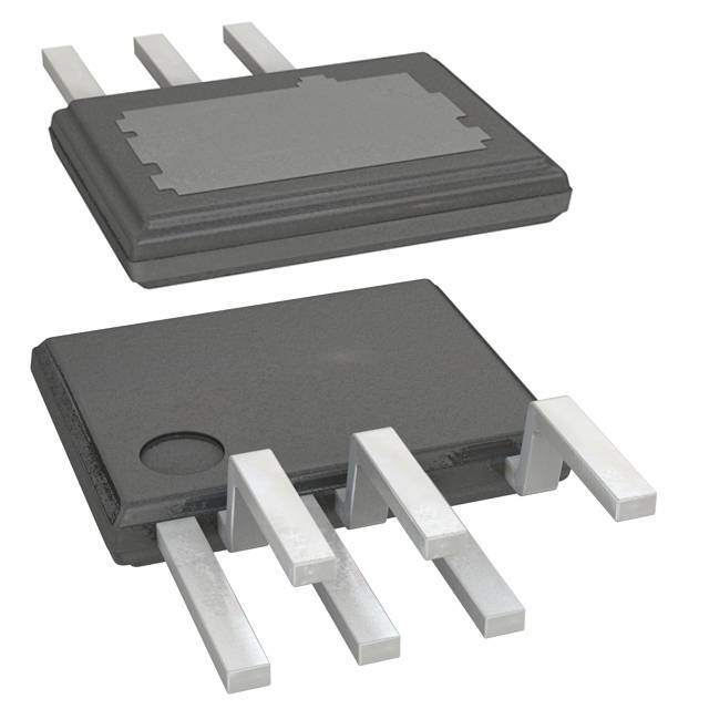
| 描述 | IC LED DRIVER 12W ESIP-7CLED照明驱动器 LED DRIVER 15 W (85-308 VAC) |
| 产品分类 | |
| 品牌 | Power Integrations |
| 产品手册 | |
| 产品图片 |
|
| rohs | 符合RoHS无铅 / 符合限制有害物质指令(RoHS)规范要求 |
| 产品系列 | LED照明电子器件,LED照明驱动器,Power Integrations LNK414EGLinkSwitch®-PH |
| 数据手册 | |
| 产品型号 | LNK414EG |
| 产品种类 | LED照明驱动器 |
| 供应商器件封装 | eSIP-7C |
| 其它名称 | 596-1384 |
| 内部驱动器 | 是 |
| 包装 | 管件 |
| 商标 | Power Integrations |
| 安装类型 | 通孔 |
| 安装风格 | Through Hole |
| 封装 | Tube |
| 封装/外壳 | 7-SIP,6 引线,裸露焊盘,成形引线 |
| 封装/箱体 | eSIP-7C |
| 工作温度 | -20°C ~ 125°C |
| 工作频率 | 66 kHz |
| 工厂包装数量 | 48 |
| 恒压 | - |
| 恒流 | 是 |
| 拓扑 | 交直流离线开关,PWM |
| 最大工作温度 | + 125 C |
| 最大电源电流 | 2.25 mA |
| 最小工作温度 | - 20 C |
| 标准包装 | 48 |
| 电压-电源 | 90 V ~ 265 V |
| 电压-输出 | - |
| 类型-初级 | 通用 |
| 类型-次级 | - |
| 输入电压 | 90 VAC to 265 VAC |
| 输出数 | 1 |
| 输出电流 | 330 mA |
| 频率 | 62kHz ~ 70kHz |


- 商务部:美国ITC正式对集成电路等产品启动337调查
- 曝三星4nm工艺存在良率问题 高通将骁龙8 Gen1或转产台积电
- 太阳诱电将投资9.5亿元在常州建新厂生产MLCC 预计2023年完工
- 英特尔发布欧洲新工厂建设计划 深化IDM 2.0 战略
- 台积电先进制程称霸业界 有大客户加持明年业绩稳了
- 达到5530亿美元!SIA预计今年全球半导体销售额将创下新高
- 英特尔拟将自动驾驶子公司Mobileye上市 估值或超500亿美元
- 三星加码芯片和SET,合并消费电子和移动部门,撤换高东真等 CEO
- 三星电子宣布重大人事变动 还合并消费电子和移动部门
- 海关总署:前11个月进口集成电路产品价值2.52万亿元 增长14.8%


PDF Datasheet 数据手册内容提取
This product is not recommended for new designs. LNK403-410/413-420 LinkSwitch-PH LED Driver IC Family Single-Stage PFC, Primary-Side Constant Current Control and TRIAC Dimming/Non-Dimming Options Product Highlights Dramatically Simplifies Off-line LED Drivers • Single-stage combination of power factor correction and accurate constant-current (CC) output • Enables very long lifetime designs (no electrolytic capacitors) • Eliminates optocoupler and all secondary current control RV circuitry AC IN • Eliminates control loop compensation circuitry D V LinkSwitch-PH • Simple primary-side PWM dimming interface CONTROL BP • Universal input voltage range • LNK403-410 optimized for flicker-free TRIAC dimming S R FB EcoSmart™ – Energy Efficient PI-6543-082211 • Single-stage PFC combined with output CC control Figure 1. Typical Application Schematic. • Greatly increases efficiency, >90% achievable • Reduces component count • No current sense resistors Output Power Table1,2 • Low standby power remote ON/OFF feature R = 2 MW R = 4 MW (<50 mW at 230 VAC) V V 85-132 VAC 85-308 VAC Product5 Accurate and Consistent Performance Minimum Maximum Minimum Maximum Output Output Output Output • Compensates for transformer inductance variations Power3 Power4 Power3 Power4 • Compensates for line input voltage variation LNK403/413E/L 2.5 W 4.5 W 6.5 W 12 W • Frequency jittering greatly reduces EMI filter size and cost LNK404/414E/L 2.5 W 5.5 W 6.5 W 15 W Advanced Protection and Safety Features LNK405/415E/L 3.8 W 7.0 W 8.5 W 18 W • Auto-restart for short-circuit protection LNK406/416E/L 4.5 W 8.0 W 10 W 22 W • Open circuit fault detection mode LNK407/417E/L 5.5 W 10 W 12 W 25 W • Automatic thermal shutdown restart with hysteresis • Meets high voltage creepage requirement between DRAIN and LNK408/418E/L 6.8 W 13.5 W 16 W 35 W all other signal pins both on PCB and at package LNK409/419E/L 8.0 W 20 W 18 W 50 W LNK410/420E/L 18 W 31 W 40 W 78 W Green Package • Halogen free and ROHS compliant package Table 1. Output Power Table. Notes: Applications 1. Continuous power in an open frame with adequate heat sinking at device local ambient of 70 °C. • Off-line LED driver 2. Power level calculated on typical LED string voltage with efficiency >80%. 3. Minimum output power with C = 10 mF. BP Description 4. Maximum output power with C = 100 mF. LNK4x3EG C = 10 mF. BP BP 5. Package: eSIP-7C, eSIP-7F. The LinkSwitch™-PH dramatically simplifies implementation of LED drivers requiring long lifetime, high efficiency, PF >0.9, and TRIAC dimming capability (LNK403-410). The single-stage combined power factor and constant-current controller eliminates a switching stage and the electrolytic bulk capacitor. The advanced primary-side control used by the LinkSwitch-PH device provides accurate constant current control while eliminating the need for an optocoupler and current sensing circuits. LinkSwitch-PH incorporates a 725 V power FET, a continuous- eSIP-7C (E Package) eSIP-7F (L Package) mode PWM controller, a high-voltage switched current source for self biasing, frequency jittering, protection circuitry including Figure 2. Package Options. cycle-by-cycle current limit and hysteretic thermal shutdown. www.power.com June 2015 This Product is Covered by Patents and/or Pending Patent Applications.
LNK403-410/413-420 DRAIN (D) BYPASS (BP) 5.9 V REGULATOR BYPASS CAPACITOR SOFT-START SELECT TIMER HYSTERETIC THERMAL SHUTDOWN FAULT + ILIM MI AUTO-RESTART PRESENT 5.9 V - 5.0 V COUNTER BYPASS PIN 1 V UNDERVOLTAGE DGraivteer VOLTAGE SenseFet MONITOR (V) STOP JITTER LOGIC CLOCK Comparator OSCILLATOR - LEB 3-VT + DFCBMOAFXF OCP UV/OV LINE + SENSE - CURRENT LIMIT FEEDBACK (FB) IV PFC/CC COMPARATOR ILIM VBG IFB CONTROL MI VSENSE FEEDBACK FBOFF SENSE DCMAX IS REFERENCE (R) REBFELORECNKCE VBG 6.4 V PI-5431-102610 SOURCE (S) Figure 3. Functional Block Diagram. Pin Functional Description VOLTAGE MONITOR (V) Pin: This pin interfaces with an external input line peak detector, DRAIN (D) Pin: consisting of a rectifier, filter capacitor and resistors. The This pin is the power FET drain connection. It also provides applied current is used to control stop logic for line under- internal operating current for both start-up and steady-state voltage (UV), overvoltage (OV), provide feed-forward to control operation. the output current and the remote ON/OFF function. SOURCE (S) Pin: This pin is the power FET source connection. It is also the Exposed Pad ground reference for the BYPASS, FEEDBACK, REFERENCE and (Backside) Internally VOLTAGE MONITOR pins. Connected to SOURCE Pin E Package (eSIP-7C) BYPASS (BP) Pin: (Top View) L Package (eSIP-7F) This is the connection point for an external bypass capacitor for 7 D the internally generated 5.9 V supply. This pin also provides 5 S output power selection through choice of the BYPASS pin 4 BP capacitor value. 3 FB 2 V 1 R FEEDBACK (FB) Pin: Exposed Pad 1 3 5 The FEEDBACK pin is used for output voltage feedback. The (backside) Internally R FB S current into the FEEDBACK pin is directly proportional to the Connected to Lead Bend Outward 2 4 7 output voltage. The FEEDBACK pin also includes circuitry to SOURCE Pin (see from Drawing V BP D eSIP-7C Package (Refer to eSIP-7F Package protect against open load and overload output conditions. Drawing) Outline Drawing) PI-5432-082411 REFERENCE (R) Pin: Figure 4. Pin Configuration. This pin is connected to an external precision resistor and is used to configure for dimming (LNK403-410) and non-TRIAC dimming (LNK413-420) modes of operation. 2 Rev. G 06/15 www.power.com
LNK403-410/413-420 Functional Description and overvoltage thresholds of the VOLTAGE MONITOR pin. For non-dimming or PWM dimming applications with LNK413-420, A LinkSwitch-PH device monolithically integrates a controller and the external resistor should be a 24.9 kW ±1%, for high-line and high-voltage power FET into one package. The controller universal input voltage designs, and 49.9 kW ±1% for low-line implements both high power factor and a constant current input voltage designs. For phase angle AC dimming with output in a single stage. The LinkSwitch-PH controller consists LNK403-410, the external resistor should be a 49.9 kW ±1%. of an oscillator, feedback (sense and logic) circuit, 5.9 V regulator, One percent resistors are recommended as the resistor hysteretic over-temperature protection, frequency jittering, tolerance directly affects the output tolerance. Other resistor cycle-by-cycle current limit, auto-restart, inductance correction, values should not be used. power factor and constant current control. BYPASS Pin Capacitor Power Gain Selection FEEDBACK Pin Current Control Characteristics LinkSwitch-PH devices have the capability to tailor the internal The figure shown below illustrates the operating boundaries of gain to either full or a reduced output power setting. This allows the FEEDBACK pin current. Above I switching is disabled selection of a larger device to minimize dissipation for both FB(SKIP) and below I the device enters into auto-restart. thermal and efficiency reasons. The power gain is selected with FB(AR) the value of the BYPASS pin capacitor. The full power setting is selected with a 100 mF capacitor and the reduced power setting IFB(SKIP) Skip-Cycle (for higher efficiency) is selected with a 10 mF capacitor. The BYPASS pin capacitor sets both the internal power gain as well as the over-current protection (OCP) threshold. Unlike the larger devices, the LNK4x3 power gain is not programmable. Use a 10 mF capacitor for the LNK4x3. IFB CCR eCgoinotnrol Switching Frequency The switching frequency is 66 kHz. To further reduce the EMI level, the switching frequency is jittered (frequency modulated) by approximately ±1 kHz. I Soft-Start FB(DCMAXR) The controller includes a soft-start timing feature which inhibits the auto-restart protection feature for the soft-start period (t ) Soft-Start and SOFT to distinguish start-up into a fault (short-circuit) from a large CC Fold-Back Region output capacitor. At start-up the LinkSwitch-PH clamps the maximum duty cycle to reduce the output power. The total soft-start period is t . SOFT Remote ON/OFF and EcoSmart The VOLTAGE MONITOR pin has a 1 V threshold comparator connected at its input. This voltage threshold is used for IFB(AR) Auto-Restart remote ON/OFF control. When a signal is received at the VOLTAGE MONITOR pin to disable the output (VOLTAGE DC10 DC MAX MONITOR pin tied to ground through an optocoupler photo- Maximum Duty Cycle PI-5433-060410 transistor) the LinkSwitch-PH will complete its current switching Figure 5. FEEDBACK Pin Current Characteristic. cycle before the internal power FET is forced off. The FEEDBACK pin current is also used to clamp the maximum The remote ON/OFF feature can also be used as an eco-mode duty cycle to limit the available output power for overload and or power switch to turn off the LinkSwitch-PH and keep it in a open-loop conditions. This duty cycle reduction characteristic very low power consumption state for indefinite long periods. also promotes a monotonic output current start-up characteristic When the LinkSwitch-PH is remotely turned on after entering to prevent over-shoot. this mode, it will initiate a normal start-up sequence with soft-start the next time the BYPASS pin reaches 5.9 V. In the REFERENCE Pin worst case, the delay from remote on to start-up can be equal The REFERENCE pin is tied to ground (SOURCE) via an external to the full discharge/charge cycle time of the BYPASS pin. This resistor. The value selected sets the internal references, reduced consumption remote off mode can eliminate expensive determining the operating mode for dimming (LNK403-410) and and unreliable in-line mechanical switches. non-dimming (LNK413-420) operation and the line undervoltage 3 www.power.com Rev. G 06/15
LNK403-410/413-420 Over-Current Protection The current limit circuit senses the current in the power FET. When this current exceeds the internal threshold (I ), the power LIMIT FET is turned off for the remainder of that cycle. A leading edge D V blanking circuit inhibits the current limit comparator for a short CONTROL time (t ) after the power FET is turned on. This leading edge BP blankinLEgB time has been set so that current spikes caused by capacitance and rectifier reverse recovery will not cause S R FB premature termination of the power FET conduction. Line Under/Overvoltage Protection This device includes both line under- and overvoltage detection to limit the minimum start-up and maximum operating voltage detected through the VOLTAGE MONITOR pin. An external peak PI-5435-052510 detector consisting of a diode and capacitor are required to provide input line peak voltage to the VOLTAGE MONITOR pin Figure 6. Remote ON/OFF VOLTAGE MONITOR pin Control through a resistor. At power up, I keeps the LinkSwitch-PH UV+ 5.9 V Regulator/Shunt Voltage Clamp off until the input line voltage reaches the undervoltage threshold. The internal 5.9 V regulator charges the bypass capacitor At power down, I prevents restart attempts after the output UV- connected to the BYPASS pin to 5.9 V by drawing a current goes out of regulation. from the voltage on the DRAIN pin whenever the power FET is off. The BYPASS pin is the internal supply voltage node. When The same resistor used for UV also sets line overvoltage (OV) the power FET is on, the device operates from the energy shutdown threshold which, once exceeded, forces the stored in the bypass capacitor. Extremely low power LinkSwitch-PH to stop switching (after completion of the current consumption of the internal circuitry allows LinkSwitch-PH switching cycle). Once the line voltage returns to normal, the to operate continuously from current it takes from the DRAIN device resumes normal operation. A small amount of hysteresis pin. A bypass capacitor value of 10 or 100 mF is sufficient for is provided on the OV threshold to prevent noise triggering. both high frequency decoupling and energy storage. In When the power FET is off, the rectified DC high voltage surge addition, there is a 6.4 V shunt regulator clamping the BYPASS capability is increased to the voltage rating of the power FET pin at 6.4 V when current is provided to the BYPASS pin (725 V), due to the absence of the reflected voltage and leakage through an external resistor. This facilitates powering of spikes on the drain. LinkSwitch-PH externally through a bias winding to increase operating efficiency. It is recommended that the BYPASS pin is Hysteretic Thermal Shutdown supplied current from the bias winding for normal operation. The thermal shutdown circuitry senses the controller die temperature. The threshold is set at 142 °C typical with a 75 °C Auto-Restart hysteresis. When the die temperature rises above this threshold In the event of an open-loop fault (open FEEDBACK pin resistor (142 °C) the power FET is disabled and remains disabled until or broken path to feedback winding), output short-circuits or an the die temperature falls by 75 °C, at which point the power FET overload condition the controller enters into the auto-restart is re-enabled. mode. The controller annunciates both short-circuit and open-loop conditions once the FEEDBACK pin current falls Safe Operating Area (SOA) Protection below the I threshold after the soft-start period. To The device also features a safe operating area (SOA) protection minimize thFeB (ApRo)wer dissipation under this fault condition the mode which disables FET switching for 40 cycles in the event shutdown/auto-restart circuit turns the power supply on (same the peak switch current reaches the I threshold and the LIMIT as the soft-start period) and off at an auto-restart duty cycle of switch on-time is less than t . This protection mode protects ON(SOA) typically DC for as long as the fault condition persists. If the the device under short-circuited LED conditions and at start-up fault is remoAvRed during the auto-restart off-time, the power during the soft-start period when auto-restart protection is inhibited. supply will remain in auto-restart until the full off-time count is The SOA protection mode remains active in normal operation. completed. Special consideration must be made to appropriately size the output capacitor to ensure that after the soft-start period (t ) the FEEDBACK pin current is above the I SOFT FB(AR) threshold to ensure successful power-supply start-up. After the soft-start time period, auto-restart is activated only when the FEEDBACK pin current falls below I . FB(AR) 4 Rev. G 06/15 www.power.com
LNK403-410/413-420 Application Example Input Stage Fuse F1 provides protection from component failures while RV1 14 W TRIAC Dimmable High Power Factor LED Driver provides a clamp during differential line surges, keeping the Design Example peak drain voltage of U1 below the 725 V rating of the internal power FET. Bridge rectifier BR1 rectifies the AC line voltage. The circuit schematic in Figure 7 shows a TRIAC dimmable high EMI filtering is provided by L1-L3, C1, R16 and R17 together with power-factor LED driver based on LNK406EG from the the safety rated Y class capacitor (C7) that bridges the safety LinkSwitch-PH family of devices. It was optimized to drive an isolation barrier between primary and secondary. Resistor R16 LED string at a voltage of 28 V with a constant current of 0.5 A and R17 act to damp any resonances formed between L1, L2, (±5%) ideal for PAR lamp retro-fit applications. The design C1 and the AC line impedance. A small bulk capacitor (C2) is operates over a universal input voltage range of 90 VAC to required to provide a low impedance source for the primary 265 VAC but provides the specified output current tolerance switching current. The maximum value of C1 and C2 is limited in over a line voltage range of 90 VAC to 132 VAC (this is configurable order to maintain a power factor of greater than 0.9. for high-line only applications by simple component value changes). LinkSwitch-PH Primary The key goals of this design were compatibility with standard To provide peak line voltage information to U1 the incoming leading edge TRIAC AC dimmers, very wide dimming range rectified AC peak charges C3 via D2. This is then fed into the (1000:1, 500 mA:0.5 mA), high efficiency (>85%) and high power VOLTAGE MONITOR pin of U1 as a current via R2 and R3. This factor (>0.9). The design is fully protected from faults such as sensed current is also used by the device to set the line input no-load, overload and output short-circuit conditions and over overvoltage and undervoltage protection thresholds. Resistor temperature. R1 provides a discharge path for C3 with a time constant much longer than that of the rectified AC to prevent generation of line Circuit Description frequency ripple. The LinkSwitch-PH device (U1) integrates the power FET, controller and start-up functions into a single package reducing The VOLTAGE MONITOR pin current and the FEEDBACK pin the component count versus typical implementations. Configured current are used internally to control the average output LED as part of an isolated continuous conduction mode flyback current. For TRIAC phase-dimming applications a 49.9 kW converter, U1 provides high power factor via its internal control resistor (R4) is used on the REFERENCE pin and 4 MW (R2+R3) algorithm together with the small input capacitance of the on the VOLTAGE MONITOR pin to provide a linear relationship design. Continuous conduction mode operation results in between input voltage and the output current and maximizing reduced primary peak and RMS current. This both reduces the dimming range. Resistor R4 also sets the internal line input EMI noise, allowing simpler, smaller EMI filtering components and undervoltage and overvoltage protection thresholds. improves efficiency. Output current regulation is maintained without the need for secondary-side sensing which eliminates current sense resistors and improves efficiency. C8 C10 11 FL1 35300 VµF 35300 VµF 2R0 1k5Ω 28 V, 500 mA 100L03 µH MBRS4D2801T3G 751R0% 9kΩ 214/R02 1 kWΩ DLD42007 P6KVER2100A 1 F3L2 RTN L 3.1F51 A 1R k1Ω6 2K6BB0PR00 1V6M 75R101% k0Ω 5R11 01W 8Ω 21 RM%2Ω UFD43007 RTM18 2 15R08 ΩDLD46936 10R k7Ω 252C0 5 µVF 100L01 µH 21 RM%3Ω UFD44002 90V N-A 2C6527R5 VV1AC 10R0L012 7µH 27457C V1nAFC DLD41002 ZMM1V55R2 4V25B-7 262C3010 1 nVF 1603C002 nVF L41i0CnL 0µkN3 FSVKwU40i1t6cEhG-PHD CONTVROL1ND4B351PR 4k5Ω8 161R2% 6kΩ BAV21DW7S-7-F 1 kΩ 2.R4 1M1Ω FMMQT1558 155C0 6 nVF 1R151% Ω2 11R3/201 3WΩIRFQR2310 S R491R.9%4 FkBΩ110C6 4 µVF M1RM k1BΩ9QT3391050C4001 3VnFZMM1R3V059 2R2k 05V3Ω9B-7 51C0 1µ 2VF C7 2.2 nF 250 VAC PI-5997-061510 Figure 7. Schematic of an Isolated, TRIAC Dimmable, High Power Factor, Universal Input, 14 W LED Driver. 5 www.power.com Rev. G 06/15
LNK403-410/413-420 Diode D3 and VR1 clamp the drain voltage to a safe level due to 40% of the mean value. For designs where lower ripple is the effects of leakage inductance. Diode D4 is necessary to desirable the output capacitance value can be increased. prevent reverse current from flowing through U1 for the period A small pre-load is provided by R15 which limits the output of the rectified AC input voltage that the voltage across C2 falls voltage under no-load conditions. to below the reflected output voltage (V ). OR TRIAC Phase Dimming Control Compatibility Diode D6, C5, R7 and R8 create the primary bias supply from The requirement to provide output dimming with low cost, an auxiliary winding on the transformer. Capacitor C4 provides TRIAC-based, leading edge phase dimmers introduces a local decoupling for the BYPASS pin of U1 which is the supply number of trade-offs in the design. pin for the internal controller. During start-up C4 is charged to ~6 V from an internal high-voltage current source tied to the Due to the much lower power consumed by LED based lighting device DRAIN pin. This allows the part to start switching at the current drawn by the overall lamp is below the holding which point the operating supply current is provided from the current of the TRIAC within the dimmer. This can cause bias supply via R5. Capacitor C4 also selects the output power undesirable behaviors such as limited dimming range and/or mode (10 mF for reduced power was selected to reduce flickering as the TRIAC fires inconsistently. The relatively large dissipation in U1 and increase efficiency). impedance the LED lamp presents to the line allows significant ringing to occur due to the inrush current charging the input Feedback capacitance when the TRIAC turns on. This too can cause The bias winding voltage is proportional to the output voltage similar undesirable behavior as the ringing may cause the (set by the turns ratio between the bias and secondary TRIAC current to fall to zero and turn off. windings). This allows the output voltage to be monitored without secondary-side feedback components. Resistor R6 To overcome these issues two circuits, the Active Damper and converts the bias voltage into a current which is fed into the Passive Bleeder, are incorporated. The drawback of these FEEDBACK pin of U1. The internal engine within U1 combines circuits is increased dissipation and therefore reduced efficiency the FEEDBACK pin current, VOLTAGE MONITOR pin current of the supply. For non-dimming applications these components and drain current information to provide a constant output can simply be omitted. current over a 1.5:1 output voltage variation (LED string voltage variation of ±25%) at a fixed line input voltage. The Active Damper consists of components R9, R10, R11, R12, D1, Q1, C6, VR2, Q2 in conjunction with R13. This circuit limits To limit the output voltage at no-load an output overvoltage the inrush current that flows to charge C2 when the TRIAC protection circuit is set by D7, C12, R20, VR3, C13, Q3 and R19. turns on by placing R13 in series for the first 1 ms of the TRIAC Should the output load be disconnected then the bias voltage conduction. After approximately 1 ms, Q2 turns on and shorts will increase until VR3 conducts, turning on Q3 and reducing R13. This keeps the power dissipation on R13 low and allows a the current into the FEEDBACK pin. When this current drops larger value during current limiting. Resistor R9, R10, R11 and below 20 mA the part enters auto-restart and switching is C6 provide the 1 ms delay after the TRIAC conducts. Transistor disabled for 1500 ms allowing time for the output and bias Q1 discharges C6 when the TRIAC is not conducting and VR2 voltages to fall. clamps the gate voltage of Q2 to 15 V. Output Rectification The Passive Bleeder circuit is comprised of C11 and R18. This The transformer secondary winding is rectified by D8 and helps to keep the input current above the TRIAC holding current filtered by C8 and C10. A Schottky barrier diode was selected while the input current corresponding to the effective driver for efficiency and the combined value of C8 and C10 were resistance increases during each AC half-cycle. selected to give peak-to-peak and LED ripple current equal to 6 Rev. G 06/15 www.power.com
LNK403-410/413-420 7 W High Power Factor Non-Dimmable LED Driver and R11, R12 (1.402 MW) connected to the VOLTAGE MONITOR Design Example with Enhanced Line Regulation pin provides excellent line regulation over the entire 90 VAC to 265 VAC input range. The circuit schematic in Figure 8 shows a high power-factor LED driver based on a LNK413EG from the LinkSwitch-PH The VOLTAGE MONITOR pin current is also used by the device family of devices. It was optimized to drive an LED string at a to set the line input overvoltage and undervoltage protection voltage of 21 V with a constant current of 0.33 A, ideal for thresholds. PAR20/PAR30 lamp retro-fit applications. The design operates over the universal input voltage range of 90 VAC to 265 VAC Diode D1 and VR1 clamp the drain voltage to a safe level due to and is a non-dimming application. A non-dimming application the effects of leakage inductance. A Zener clamp was selected has tighter output current variation with changes in the line for lowest component count and highest efficiency. Diode D5 is voltage than a dimming application. It’s key to note that, although necessary to prevent reverse current from flowing through U1 not specified for dimming, no circuit damage will result if the during the period when the AC input voltage is lower than the end user does operate the design with a phase controlled reflected output voltage (V ). A space efficient RM6 core was OR dimmer. selected for this design. The RM core geometry helps minimizes audible noise but requires the use of flying leads to meet safety Circuit Description spacing requirements. Input Stage Fuse F1 provides protection from component failures while RV1 Diode D3, C6, R5, R9 and R18 create the primary bias supply provides a clamp during differential line surges, keeping the from an auxiliary winding on the transformer. Resistor R5 peak drain voltage of U1 below the 725 V rating of the internal provides filtering of leakage inductance generated voltage power FET. Bridge rectifier BR1 rectifies the AC line voltage. spikes to improve tracking of the bias and output voltages. It EMI filtering is provided by L1-L3, C2 together with the safety also forms a pole with C6 at ~100 Hz. Resistors R9 and R18 rated Y class capacitor (C7) that bridges the safety isolation act as a small load to ensure that the bias voltage collapses barrier between primary and secondary. Resistor R2 and R3 during output short-circuit when U1 enters auto-restart act to damp any resonances formed between L1, L2, C2 and operation to protect the supply. the AC line impedance. A small bulk capacitor (C3) is required to provide a low impedance source for the primary switching Output overvoltage and load disconnection protection is current. The maximum value of C2 and C3 is limited in order to provided by D8, C14, R24, VR3, C15, R23 and Q2. Should the maintain a power factor of greater than 0.9. output LED load become disconnected the output voltage will rise causing an associated rise in the bias winding voltage LinkSwitch-PH Primary across C14. Once this exceeds the voltage rating of VR3, Q2 To provide peak line voltage information to U1 the incoming turns on pulling down the FEEDBACK pin of U1 and initiating rectified AC peak charges C8 via D6. This is then fed into the auto-restart operation. Once in auto-restart the low duty cycle VOLTAGE MONITOR pin of U1 as a current via R4, R7 and R8. of operation (~3%) together with the small pre-load on the The VOLTAGE MONITOR pin current and the FEEDBACK pin output prevents the output voltage rising to a high level. Once current are used internally to control the average output LED the output load is reconnected normal operation resumes. current. The combined value of R4, R7 and R8 (3.909 MW) C5 C4 FL1 FL2 13550 VµF 13550 VµF 20R k6Ω 21 V, 330 mA 100L03 µH MBRS4D2201T3G DLD46007 P6KVER2100A 1 FL3 RTN 6 L 3.1F51 A 1R k2Ω DF066B0SR0- 1EV3/45 2111 RRMM%%47ΩΩ UFD41007 RTM16 2 7R5 5Ω DLD439361R0 1k8Ω10R k9Ω 252C0 6 µVF 100L01 µH C2 1400C003 nVF 410C 0µ8 FV 901R9% 8kΩ EDS15D 90V -A 2C6527R5 VV1AC L2 27252 VnAFC 1ND44148 1000 µH R10 D V 3 kΩ R15 N R3 1.R01 1%M1Ω LinLkNSKwU41i1t3cEhG-PH CONTROL BP 150 kΩ BAV21DW8S-7-F 1 kΩ VR3 40R121% k2Ω S R24R1.91%F 9kBΩ11C001 µ2VF M1R Mk2Ω3BQT2391050C4001 5VnFZMM1R3059 22k 45VΩ9B-7 51C0 1µ 4VF C7 2.2 nF 250 VAC PI-5991-101210 Figure 8. Schematic of an Isolated, Non-Dimmable, High Power Factor, Universal Input, 7 W LED Driver. 7 www.power.com Rev. G 06/15
LNK403-410/413-420 Capacitor C12 provides local decoupling for the BYPASS pin of therefore lower conduction losses. For open frame design or U1 which is the supply pin for the internal controller. During designs where space is available for heat sinking then refer to start-up C4 is charged to ~6 V from an internal high-voltage the maximum output power column. This is selected by using current source tied to the device DRAIN pin. Once the bias a 100 mF BYPASS pin capacitor for all but the LNK4x3 which voltage has risen into regulation the operating supply current is has only one power setting. In all cases in order to obtain the provided via R10. Diode D4 prevents U1 from charging C6 best output current tolerance maintain the device temperature during start-up which would increase the start-up delay time. below 100 °C Feedback Maximum Input Capacitance The bias winding voltage is proportional to the output voltage To achieve high power factor, the capacitance used in both the (set by the turns ratio between the bias and secondary EMI filter and for decoupling the rectified AC (bulk capacitor) windings). This allows the output voltage to be monitored must be limited in value. The maximum value is a function of without secondary-side feedback components. Resistor R15 the output power of the design and reduces as the output converts the bias voltage into a current which is fed into the power reduces. For the majority of designs limit the total FEEDBACK pin of U1. The internal engine within U1 combines capacitance to less than 200 nF with a bulk capacitor value of the FEEDBACK pin current, VOLTAGE MONITOR pin current 100 nF. Film capacitors are recommended compared to and drain current information to provide a constant output ceramic types as they minimize audible noise with operating current over a 2:1 output voltage range. with leading edge phase dimmers. Start with a value of 10 nF for the capacitance in the EMI filter and increase in value until Output Rectification there is sufficient EMI margin. The transformer secondary winding is rectified by D2 and filtered by C4 and C5. A Schottky barrier diode was selected REFERENCE Pin Resistance Value Selection for efficiency and the combined value of C4 and C5 were The LinkSwitch-PH family contains phase dimming devices, selected to give an acceptable LED ripple current. For designs LNK403-410, and non-dimming devices, LNK413-420. The where lower ripple is desirable the output capacitance value non-dimmable devices use a 24.9 kW ±1% REFERENCE pin can be increased. A small pre-load is provided by R6 which resistor in high-line and universal input voltage designs and limits the output voltage under no-load conditions. 49.9 kW ±1% in low-line input voltage designs, for best output current tolerance (over AC input voltage changes). The dimmable Key Application Considerations devices use 49.9 kW ±1% to achieve the widest dimming range. Power Table VOLTAGE MONITOR Pin Resistance Network Selection The data sheet power table (Table 1) represents the minimum For widest AC phase angle dimming range with LNK403-410, and maximum practical continuous output power based on the use a 4 MW resistor connected to the line voltage peak detector following conditions: circuit. Make sure that the resistor’s voltage rating is sufficient for the peak line voltage. If necessary use multiple series 1. Efficiency of 80% connected resistors. 2. Device local ambient of 70 °C 3. Sufficient heat sinking to keep the device temperature For best line regulation, use a series combination of resistors below 100 °C that equals 3.909 MW connected to the line voltage peak 4. For minimum output power column detector. In addition, connect a 1 MW in series with a 402 kW • Reflected output voltage (V ) of 120 V resistor (1.402 MW total) from the VOLTAGE MONITOR pin to OR • FEEDBACK pin current of 135 mA SOURCE pin. Use 1% tolerance resistors for good accuracy. • BYPASS pin capacitor value of 10 mF Line regulation can be further improved by using the PIXls 5. For maximum output power column spreadsheet’s fine tuning section. See the LinkSwitch-PH • Reflected output voltage (V ) of 65 V Application Note for more information. OR • FEEDBACK pin current of 165 mA • BYPASS pin capacitor value of 100 mF Primary Clamp and Output Reflected Voltage V OR (LNK4x3EG = 10 mF) A primary clamp is necessary to limit the peak drain to source voltage. A Zener clamp requires the fewest components and Note that input line voltages above 85 VAC do not change the board space and gives the highest efficiency. RCD clamps are power delivery capability of LinkSwitch-PH devices. also acceptable however the peak drain voltage should be carefully verified during start-up and output short-circuit as the Device Selection clamping voltage varies with significantly with the peak drain Select the device size by comparing the required output power current. to the values in Table 1. For thermally challenging designs, e.g., incandescent lamp replacement, where either the ambient For the highest efficiency, the clamping voltage should be temperature local to the LinkSwitch-PH device is high and/or selected to be at least 1.5 times the output reflected voltage, there is minimal space for heat sinking use the minimum output V , as this keeps the leakage spike conduction time short. OR power column. This is selected by using a 10 mF BYPASS pin When using a Zener clamp in a universal input or high-line only capacitor and results in a lower device current limit and application, a V of less than 135 V is recommended to allow OR 8 Rev. G 06/15 www.power.com
LNK403-410/413-420 for the absolute tolerances and temperature variations of the Zener. This will ensure efficient operation of the clamp circuit V) 350 PI-5983-060810 0.35 A) abnreda wkdilol awlsno v koelteapg eth oef mthae xFimETu.m A dnr aRinC Dvo (lotar gReC bDeZlo) wcl athmep r ated put) ( 250 VCoulrtraegnet 0.25 mer) ( n m provides tighter clamp voltage tolerance than a Zener clamp. er I 150 0.15 Di The RCD clamp is more cost effective than the Zener clamp but m h requires more careful design to ensure that the maximum drain Dim 50 0.05 oug voltage does not exceed the power FET breakdown voltage. at -500.5 50 100 150 200 250 300 350 400-0.05 Thr These VOR limits are based on the BVDSS rating of the internal ge ( nt ( FET, a V of 60 V to 100 V is typical for most designs, giving a-150 -0.15 e tSheer ibeess Dt OPrRaFiCn aDniodd reegulation performance. Line Volt--235500 --00..2355 Line Curr An ultra-fast or Schottky diode in series with the drain is necessary to prevent reverse current flowing through the Conduction Angle (°) device. The voltage rating must exceed the output reflected 350 PI-5984-060810 0.35 voltage, V . The current rating should exceed two times the OR amLvinaexerai mVgoeul mtpar dgimreaa iPrnye cacuukrr rDreenenttt e oacfn ttdoh erh Csaevirelec caut ieptde aLkin rkaStinwgit cehq-uPaHl t od ethviec e. oltage (V) 320500 VCoulrtraegnet 00..325 urrent (A) LinkSwitch-PH devices use the peak line voltage to regulate the ut V 200 0.2 ut C power delivery to the output. A capacitor value of 1 mF to 4.7 mF p p n 150 0.15 n is recommended to minimize line ripple and give the highest d I d I ploowweer rP fFa catnodr (h>i0g.h9e),r slimnea lcleurr rveanlut edsis atorer taiocnc.e ptable but result in ctifie 100 0.1 ctifie e e R 50 0.05 R Operation with Phase Controlled Dimmers 0 0 Dimmer switches control incandescent lamp brightness by not 0 50 100 150 200 250 300 350 400 conducting (blanking) for a portion of the AC voltage sine wave. This reduces the RMS voltage applied to the lamp thus reducing Conduction Angle (°) the brightness. This is called natural dimming and the Figure 9. (a) Ideal Input Voltage and Current Waveforms for a Leading Edge LinkSwitch-PH LNK403-410 devices when configured for TRIAC Dimmer at 90° Conduction Angle. (b) Resultant Waveforms Following Rectification of TRIAC Dimmer Output. dimming utilize natural dimming by reducing the LED current as the RMS line voltage decreases. By this nature, line regulation performance is purposely decreased to increase the dimming Figure 9(a) shows the line voltage and current at the input of a range and more closely mimic the operation of an incandescent leading edge TRIAC dimmer with Figure 9(b) showing the lamp. Using a 49.9 kW REFERENCE pin resistance selects resultant rectified bus voltage. In this example, the TRIAC natural dimming mode operation. conducts at 90 degrees. Leading Edge Phase Controlled Dimmers Figure 10 shows undesired rectified bus voltage and current The requirement to provide flicker-free output dimming with low with the TRIAC turning off prematurely and restarting. cost, TRIAC-based, leading edge phase dimmers introduces a number of trade-offs in the design. If the TRIAC is turning off before the end of the half-cycle erratically or alternate half AC cycles have different conduction Due to the much lower power consumed by LED based lighting angles then flicker will be observed in the LED light due to the current drawn by the overall lamp is below the holding variations in the output current. This can be solved by including current of the TRIAC within the dimmer. This causes undesirable a bleeder and damper circuit. behaviors such as limited dimming range and/or flickering. The relatively large impedance the LED lamp presents to the line Dimmers will behave differently based on manufacturer and allows significant ringing to occur due to the inrush current power rating, for example a 300 W dimmer requires less charging the input capacitance when the TRIAC turns on. This dampening and requires less power loss in the bleeder than a too can cause similar undesirable behavior as the ringing may 600 W or 1000 W dimmer due to different drive circuits and cause the TRIAC current to fall to zero and turn off. TRIAC holding current specifications. Line voltage also has a significant impact as at high-line for a given output power the To overcome these issues two circuits, the Active Damper and input current and therefore TRIAC current is lower but the peak Passive Bleeder, are incorporated. The drawback of these inrush current when the input capacitance charges is higher circuits is increased dissipation and therefore reduced efficiency creating more ringing. Finally multiple lamps in parallel driven of the supply so for non-dimming applications these from the same dimmer can introduce more ringing due to the components can simply be omitted. 9 www.power.com Rev. G 06/15
LNK403-410/413-420 350 PI-5985-102810 0.35 350 PI-5986-060810 0.35 nput Voltage (V) 322105050000 VCoulrtraegnet 0000....322155 nput Current (A) utput Voltage (V) 21-55550000 0 50 100 150 200 250 300VCoulrtraegnet350 000-0...210.05555 utput Current (A) ctified I 100 0.1 ctified I mmer O-150 -0.15 mmer O Re 50 0.05 Re Di-250 -0.25 Di 0 0 -350 -0.35 0 50 100 150 200 250 300 350 400 Conduction Angle (°) Conduction Angle (°) Figure 11. Ideal Dimmer Output Voltage and Current Waveforms for a Trailing Edge Figure 10. Example of Phase Angle Dimmer Showing Erratic Firing. Dimmer at 90° Conduction Angle. increased capacitance of parallel units. Therefore when testing back-to-back connected power FETs rather than a TRIAC to dimmer operation verify on a number of models, different line control the load. This eliminates the holding current issue of voltages and with both a single driver and multiple drivers in parallel. TRIACs and since the conduction begins at the zero crossing, high current surges and line ringing are minimized. Typically these Start by adding a bleeder circuit. Add a 0.44 mF capacitor and types of dimmers do not require damping and bleeder circuits. 510 W 1 W resistor (components in series) across the rectified bus (C11 and R18 in Figure 7). If this results in satisfactory Audible Noise Considerations for Use with operation reduce the capacitor value to the smallest that results Leading Edge Dimmers in acceptable performance to reduce losses and increase efficiency. Noise created when dimming is typically created by the input capacitors, EMI filter inductors and the transformer. The input If the bleeder circuit does not maintain conduction in the TRIAC, capacitors and inductors experience high di/dt and dv/dt every then add an active damper as shown in Figure 7. This consists AC half-cycle as the TRIAC fires and an inrush current flows to of components R9, R10, R11, R12, D1, Q1, C6, VR2, Q2 in charge the input capacitance. Noise can be minimized by conjunction with R13. This circuit limits the inrush current that selecting film vs ceramic capacitors, minimizing the capacitor flows to charge C2 when the TRIAC turns on by placing R13 in value and selecting inductors that are physically short and wide. series for the first 1 ms of the TRIAC conduction. After approximately 1 ms, Q2 turns on and shorts R13. This keeps The transformer may also create noise which can be minimized the power dissipation on R13 low and allows a larger value to by avoiding cores with long narrow legs (high mechanical be used during current limiting. Increasing the delay before Q2 resonant frequency). For example, RM cores produce less turns on by increasing the values of resistors R9 and R10 will audible noise than EE cores for the same flux density. Reducing improve dimmer compatibility but cause more power to be the core flux density will also reduce the noise. Reducing the dissipated across R13. Monitor the AC line current and voltage maximum flux density (BM) to 1500 Gauss usually eliminates at the input of the power supply as you make the adjustments. any audible noise but must be balanced with the increased core Increase the delay until the TRIAC operates properly but keep size needed for a given output power. the delay as short as possible for efficiency. Thermal and Lifetime Considerations Lighting applications present thermal challenges to the driver. As a general rule the greater the power dissipated in the In many cases the LED load dissipation determines the working bleeder and damper circuits, the more dimmer types will work ambient temperature experienced by the drive so thermal with the driver. evaluation should be performed with the driver inside the final Trailing Edge Phase Controlled Dimmers enclosure. Temperature has a direct impact on driver and LED Figure 11 shows the line voltage and current at the input of the lifetime. For every 10 °C rise in temperature, component life is power supply with a trailing edge dimmer. In this example, the reduced by a factor of 2. Therefore it is important to properly dimmer conducts at 90 degrees. Many of these dimmers use heat sink and verify the operating temperatures of all devices. 10 Rev. G 06/15 www.power.com
LNK403-410/413-420 Layout Considerations Primary-Side Connections Use a single point (Kelvin) connection at the negative terminal of same rules as the BYPASS pin capacitor. It is critical that the the input filter capacitor for the SOURCE pin and bias returns. main power FET switching currents return to the bulk capacitor This improves surge capabilities by returning surge currents with the shortest path as possible. Long high current paths from the bias winding directly to the input filter capacitor. The create excessive conducted and radiated noise. BYPASS pin capacitor should be located as close to the BYPASS pin and connected as close to the SOURCE pin as Secondary-Side Connections possible. The SOURCE pin trace should not be shared with the The output rectifier and output filter capacitor should be as main power FET switching currents. All FEEDBACK pin close as possible. The transformer’s output return pin should components that connect to the SOURCE pin should follow the have a short trace to the return side of the output filter capacitor. Bulk Capacitor Clamp LNK403EG FL1 6 1 Input EMI Filter R14 2 VR1 R2 Transformer D1 L3 C3 5 U1 C9 C8 4 3 F1 T1 L1 C2 R L RV1 L2 C1 15 C7 FL 5 3 N C12 R 2 3 F L 2 C5 R3 Output VR3 C4 Filter R24 R16 Capacitors C14 V Copper Area for R10 C6 Heat Sinking D8 V BYPASS Pin Capacitor PI-5987-060110 Figure 12. RD-193 7 W Layout Example, Top Layer. 11 www.power.com Rev. G 06/15
LNK403-410/413-420 R13 D6 R12 D1 D7 D5 D1 R17 R R5 1 9 S D3 R20 C13 S R7 R4 BR1 VR2 Output Rectifier Bridge Rectifier R9 D2 F1 B3 R18 R6 Active Damper MOSFET PI-5988-060110 Figure 13. RD-193 7 W Layout Example, Bottom Layer. Quick Design Checklist Maximum Drain Voltage Verify that the peak V does not exceed 725 V under all DS operating conditions including start up and fault conditions. Maximum Drain Current Measure the peak drain current under all operation conditions including start up and fault conditions. Look for signs of transformer saturation (usually occurs at highest operating ambient temperatures). Verify that the peak current is less that stated for the Absolute Maximum Rating in the data sheet. Thermal Check At maximum output power, both minimum and maximum line voltage and ambient temperature; verify that temperature specifications are not exceeded for the LinkSwitch-PH, transformer, output diodes, output capacitors and drain clamp components. 12 Rev. G 06/15 www.power.com
LNK403-410/413-420 Absolute Maximum Ratings(1,4) DRAIN Pin Peak Current(5): LNK403, LNK413 ...................1.37 A Operating Junction Temperature(2) .........................-40 to 150 °C LNK404, LNK414 ...................2.08 A LNK405, LNK415 ...................2.72 A Notes: LNK406, LNK416 ..................4.08 A 1. All voltages referenced to SOURCE, T = 25 °C. A LNK407, LNK417 ..................5.44 A 2. Normally limited by internal circuitry. LNK408, LNK418 ..................6.88 A 3. 1/16 in. from case for 5 seconds. LNK409, LNK419 ...................7.73 A 4. Absolute Maximum Ratings specified may be applied, one LNK410, LNK420 ..................9.00 A at a time without causing permanent damage to the DRAIN Pin Voltage ……………………… ................ -0.3 to 725 V product. Exposure to Absolute Maximum Ratings for BYPASS Pin Voltage ............................................... -0.3 to 9 V extended periods of time may affect product reliability. BYPASS Pin Current ....................................................100 mA 5. Peak DRAIN current is allowed while the DRAIN voltage is VOLTAGE MONITOR Pin Voltage ............................-0.3 to 9 V(6) simultaneously less than 400 V. See also Figure 17. FEEDBACK Pin Voltage …….. .................................. -0.3 to 9 V 6. During start-up (the period before the BYPASS pin begins REFERENCE Pin Voltage ..........................................-0.3 to 9 V powering the IC) the VOLTAGE MONITOR pin voltage can Lead Temperature(3) ....................................................... .........260 °C safely rise to 15 V without damage. Storage Temperature ..........................................-65 to 150 °C Thermal Resistance Thermal Resistance: eSIP Package: Notes: (q ) ....................................................105 °C/W(1) 1. Free Standing with no heat sink. JA (q ) ....................................................2 °C/W(2) 2. Measured at back surface tab. JC Conditions Parameter Symbol SOURCE = 0 V; T = -20 °C to 125 °C Min Typ Max Units J (Unless Otherwise Specified) Control Functions Average 62 66 70 Switching Frequency f T = 25 °C kHz OSC J Peak-Peak Jitter 9 Frequency Jitter T = 25 °C f J 1 kHz Modulation Rate M See Note B LNK403, LNK413 -5.0 -4.2 -3.4 V = 0 V, LNK404, LNK414 -9.6 -8.0 -6.4 I BP CH1 T = 25 °C LNK405-410, J -17 -12 -8.8 BYPASS Pin LNK415-420 mA Charge Current LNK403, LNK413 -1.6 -1.2 -0.6 V = 5 V, LNK404, LNK414 -4.2 -3.5 -2.8 I BP CH2 T = 25 °C LNK405-410, J -9 -6.8 -4.6 LNK415-420 Charging Current See Note A 0.5 %/°C Temperature Drift BYPASS Pin Voltage V 0 °C < T < 100 °C 5.7 5.9 6.1 V BP J BYPASS Pin Voltage V 0 °C < T < 100 °C 0.85 V Hysteresis BP(H) J BYPASS Pin I = 2 mA V BP 6.0 6.4 6.7 V Shunt Voltage BP(SHUNT) 0 °C < T < 100 °C J T = 25 °C Soft-Start Time t J 40 ms SOFT V = 5.9 V BP 13 www.power.com Rev. G 06/15
LNK403-410/413-420 Conditions Parameter Symbol SOURCE = 0 V; T = -20 °C to 125 °C Min Typ Max Units J (Unless Otherwise Specified) Control Functions (cont.) 0 °C < T < 100 °C I J 0.5 0.85 1.2 CD2 FET Not Switching Drain Supply Current mA 0 °C < T < 100 °C I J 0.9 1.5 2.25 CD1 FET Switching at f OSC VOLTAGE MONITOR Pin Line Brown-In R = 24.9 kW 21.0 22.5 24.0 I T = 25 °C R mA Threshold Current UV+ J R = 49.9 kW 22.8 24.5 26.2 R Line Brown-Out R = 24.9 kW 18.5 I T = 25 °C R mA Threshold Current UV- J R = 49.9 kW 15.0 R Line Brown-In/Out R = 24.9 kW 1 4 I T = 25 °C R mA Hysteresis UV(H) J R = 49.9 kW 5 9.4 R T = 25 °C Threshold 107 112 117 Line Overvoltage J I R = 24.9 kW mA Threshold OV R R = 49.9 kW Hysteresis 4 R VOLTAGE MONITOR Pin 0 °C < T < 100 °C V J 2.75 3.0 3.25 V Voltage V I < I < I UV- V OV VOLTAGE MONITOR Pin V = 5 V I V 170 190 210 mA Short-Circuit Current V(SC) T = 25 °C J Remote ON/OFF V T = 25 °C 0.5 V Threshold V(REM) J FEEDBACK Pin FEEDBACK Pin Current at Onset of Maximum I 0 °C < T < 100 °C 85 mA FB(DCMAXR) J Duty Cycle FEEDBACK Pin Current I 0 °C < T < 100 °C 220 mA Skip Cycle Threshold FB(SKIP) J I < I < I Maximum Duty Cycle DC FB(DCMAXR) FB FB(SKIP) 90 99.9 % MAX 0 °C < T < 100 °C J I = 150 mA FEEDBACK Pin Voltage V FB 2.08 2.40 2.62 V FB 0 °C < T < 100 °C J FEEDBACK Pin V = 5 V I FB 320 400 480 mA Short-Circuit Current FB(SC) T = 25 °C J DC10 I = I , T = 25 °C, See Note B 10 FB FB(AR) J Duty Cycle Reduction DC40 I = 40 mA, T = 25 °C 20 % FB J DC60 I = 60 mA, T = 25 °C 36 FB J Auto-Restart T = 25 °C Auto-Restart ON-Time t J 40 ms AR V = 5.9 V BP Auto-Restart DC T = 25 °C 3 % Duty Cycle AR J 14 Rev. G 06/15 www.power.com
LNK403-410/413-420 Conditions Parameter Symbol SOURCE = 0 V; T = -20 °C to 125 °C Min Typ Max Units J (Unless Otherwise Specified) Auto-Restart (cont.) SOA Minimum Switch T = 25 °C t J 1.75 ms ON-Time ON(SOA) See Note B FEEDBACK Pin Current During I 0 °C < T < 100 °C 17.5 mA FB(AR) J Auto-Restart REFERENCE Pin REFERENCE Pin V 1.215 1.245 1.275 V Voltage R R = 24.9 kW R REFERENCE Pin 0 °C < T < 100 °C I J 48.45 49.70 50.95 mA Current R Current Limit/Circuit Protection di/dt = 174 mA/ms LNK404, LNK414 1.02 1.18 di/dt = 174 mA/ms LNK405, LNK415 1.24 1.44 di/dt = 225 mA/ms LNK406, LNK416 1.50 1.74 Full Power I Current Limit LIMIT(F) di/dt = 320 mA/ms LNK407, LNK417 1.77 2.06 A T = 25 °C (C = 100 mF) J BP di/dt = 350 mA/ms LNK408, LNK418 2.39 2.77 di/dt = 426 mA/ms LNK409, LNK419 3.26 3.79 di/dt = 1060 mA/ms LNK410, LNK420 4.90 5.70 di/dt = 133 mA/ms LNK403, LNK413 0.75 0.85 di/dt = 195 mA/ms LNK404, LNK414 0.81 0.94 di/dt = 192 mA/ms LNK405, LNK415 1.00 1.16 Reduced Power I di/dt = 240 mA/ms LNK406, LNK416 1.19 1.38 Current Limit LIMIT(R) A (C = 10 mF) TJ = 25 °C di/dt = 335 mA/ms LNK407, LNK417 1.42 1.66 BP di/dt = 380 mA/ms LNK408, LNK418 1.73 2.01 di/dt = 466 mA/ms LNK409, LNK419 2.35 2.73 di/dt = 1060 mA/ms LNK410, LNK420 4.90 5.70 Minimum ON-Time t + t T = 25 °C 300 500 700 ns Pulse LEB IL(D) J Leading Edge T = 25 °C t J 150 500 ns Blanking Time LEB See Note B T = 25 °C Current Limit Delay t J 150 ns IL(D) See Note B Thermal Shutdown 135 142 150 °C Temperature Thermal Shutdown 75 °C Hysteresis BYPASS Pin Power-Up Reset Threshold V 0 °C < T < 100 °C 2.25 3.5 4.25 V BP(RESET) J Voltage 15 www.power.com Rev. G 06/15
LNK403-410/413-420 Conditions Parameter Symbol SOURCE = 0 V; T = -20 °C to 125 °C Min Typ Max Units J (Unless Otherwise Specified) Output T = 25 °C 9.00 10.35 LNK403, LNK413 J I = 100 mA D T = 100 °C 13.50 15.5 J T = 25 °C 5.40 6.25 LNK404, LNK414 J I = 100 mA D T = 100 °C 8.35 9.7 J T = 25 °C 4.10 4.7 LNK405, LNK415 J I = 150 mA D T = 100 °C 6.30 7.3 J T = 25 °C 2.80 3.2 LNK406, LNK416 J I = 150 mA D T = 100 °C 4.10 4.75 J ON-State Resistance R W DS(ON) T = 25 °C 2.00 2.3 LNK407, LNK417 J I = 200 mA D T = 100 °C 3.10 3.6 J T = 25 °C 1.60 1.85 LNK408, LNK418 J I = 250 mA D T = 100 °C 2.40 2.8 J T = 25 °C 1.40 1.6 LNK409, LNK419 J I = 350 mA D T = 100 °C 2.10 2.45 J T = 25 °C 1.05 1.2 LNK410, LNK420 J I = 550 mA D T = 100 °C 1.6 1.85 J V = 6.4 V OFF-State Drain BP I V = 560 V 50 mA Leakage Current DSS DS T = 100 °C J V = 6.4 V Breakdown Voltage BV BP 725 V DSS T = 25 °C J Minimum Drain T < 100 °C 36 V Supply Voltage J Rise Time t 100 ns R Measured in a Typical Flyback Fall Time t 50 ns F NOTES: A. For specifications with negative values, a negative temperature coefficient corresponds to an increase in magnitude with increas- ing temperature and a positive temperature coefficient corresponds to a decrease in magnitude with increasing temperature. B. Guaranteed by characterization. Not tested in production. 16 Rev. G 06/15 www.power.com
LNK403-410/413-420 Typical Performance Characteristics e (pF)10000 LLLLSNNNNcaKKKKl4444in0000g3456 F,,,, LLLLaNNNNctKKKKor4444s1111:3456 0000....12358886 PI-5992-032912 300 LLLLSNNNNcaKKKKl4444in0000g3456 F,,,, LLLLaNNNNctKKKKor4444s1111:3456 0000....12358886 PI-5993-032912 anc1000 LLNNKK440078,, LLNNKK441178 01..7050 W)200 LLNNKK440078,, LLNNKK441178 01..7050 pacit LL NNKK440190,, LLNNKK441290 11..1565 er (m LL NNKK440190,, LLNNKK441290 11..1565 a w C o N 100 P100 AI R D 0 0 0 100 200 300 400 500 600 0 100 200 300 400 500 600 700 DRAIN Pin Voltage (V) DRAIN Voltage (V) Figure 14. Drain Capacitance vs. Drain Pin Voltage. Figure 15. Power vs. Drain Voltage. g) n 45 PI-5994-032912 mum Rati 1.12 PI-6010-060410 Current (A) 3 LLSNNcaKKl44in00g34 F,, LLaNNctKKor44s11:34 00..1288 N Currentolute Maxi 00..68 N 2 LNK405, LNK415 0.38 AIbs AI LNK406, LNK416 0.56 RA 0.4 R LNK407, LNK417 0.75 Do D 1 LLNNKK440089,, LLNNKK441189 11..0106 ed t 0.2 LNK410, LNK420 1.55 z LNK408 T = 25 °C ali LNK408 TCASE = 100 °C m 0 CASE or 0 0 2 4 6 8 10 12 14 16 18 20 N 0 100 200 300 400 500 600 700 800 ( DRAIN Voltage (V) DRAIN Voltage (V) Figure 16. Drain Current vs. Drain Voltage. Figure 17. Maximum Allowable Drain Current vs. Drain Voltage. 17 www.power.com Rev. G 06/15
LNK403-410/413-420 eSIP-7C (E Package) C 2 A 0.403 (10.24) 0.081 (2.06) 0.264 (6.70) 0.397 (10.08) 0.077 (1.96) Ref. B Detail A 2 0.325 (8.25) 0.290 (7.37) 0.198 (5.04) Ref. 0.320 (8.13) Ref. 0.519 (13.18) Ref. Pin #1 0.140 (3.56) 0.016 (0.41) 0.207 (5.26) I.D. 0.120 (3.05) Ref. 0.187 (4.75) 0.070 (1.78) Ref. 0.047 (1.19) 3 4 0.033 (0.84) 0.050 (1.27) 0.100 (2.54) 6× 0.016 (0.41) 0.028 (0.71) 3 0.011 (0.28)6× 0.118 (3.00) 0.010 M 0.25 M C A B 0.020 M 0.51 M C FRONT VIEW SIDE VIEW BACK VIEW 0.100 (2.54) 10° Ref. All Around 0.021 (0.53) 0.060 (1.52) 0.020 (0.50) 0.050 (1.27) 0.019 (0.48) Ref. 0.050 (1.27) PIN 1 0.048 (1.22) 0.059 (1.50) 0.155 (3.93) 0.378 (9.60) 0.046 (1.17) Ref. 0.019 (0.48) Ref. 0.023 (0.58) PIN 7 END VIEW 0.027 (0.70) 0.059 (1.50) Notes: 1. Dimensioning and tolerancing per ASME Y14.5M-1994. DETAIL A 2. Dimensions noted are determined at the outermost 0.100 (2.54) 0.100 (2.54) extremes of the plastic body exclusive of mold flash, tie bar burrs, gate burrs, and interlead flash, but including MOUNTING HOLE PATTERN any mismatch between the top and bottom of the plastic (not to scale) body. Maximum mold protrusion is 0.007 [0.18] per side. 3. Dimensions noted are inclusive of plating thickness. 4. Does not include inter-lead flash or protrusions. 5. Controlling dimensions in inches (mm). PI-4917-061510 18 Rev. G 06/15 www.power.com
LNK403-410/413-420 eSIP-7F (L Package) 2 C A 00..430937 ((1100..2048)) 00..008717 ((21..0966)) 0.264 (6.70) Ref. B Detail A 0.325 (8.25) 0.290 (7.37) 2 0.320 (8.13) 3 Ref. 0.490 (12.45) Ref. 0.198 (5.04) Ref. 0.016 (0.41) 6× 0.011 (0.28) 0.020 M 0.51 M C 0.173 (4.40) 1 7 0.084 (2.14) 0.163 (4.15) 7 1 Pin 1 I.D. 0.089 (2.26) 0.047 (1.19) Ref. 0.079 (2.01) 0.070 (1.78) Ref. 0.050 (1.27) 0.100 (2.54) 3 4 0.129 (3.28) 0.033 (0.84)6× 0.122 (3.08) 0.028 (0.71) 0.010 M 0.25 M C A B BOTTOM VIEW SIDE VIEW TOP VIEW Exposed pad hidden Exposed pad up Notes: 1 7 0.021 (0.53) 0.020 (0.50) 1. Dimensioning and tolerancing per ASME 0.060 (1.52) Ref. 0.019 (0.48) Y14.5M-1994. 2. Dimensions noted are determined at the outermost extremes of the plastic body exclusive of mold flash, tie bar burrs, gate burrs, and interlead flash, but including 0.019 (0.48) Ref. 0.023 (0.58) any mismatch between the top and bottom 0.378 (9.60) 0.048 (1.22) of the plastic body. Maximum mold Ref. 0.046 (1.17) 0.027 (0.70) protrusion is 0.007 [0.18] per side. 3. Dimensions noted are inclusive of plating thickness. END VIEW DETAIL A (Not drawn to scale) 4. Does not include inter-lead flash or protrusions. 5. Controlling dimensions in inches (mm). PI-5204-061510 Part Ordering Information • LinkSwitch Product Family • PH Series Number • Package Identifier E eSIP-7C L eSIP-7F • Package Material LNK 409 E G G GREEN: Halogen Free and RoHS Compliant Revision Notes Date A Initial Release. 06/09/10 B Updated Power Table. 08/06/10 C Added Non-Dimming parts and related text. 11/10 D Added L Package. 08/11 E Added new LNK410 and LNK420 parts. 12/11 E Updated Output Power Table values for LNK410/420. Updated Parameter Table values for LNK410/420. 05/12 F Added Note 6 to Absolute Maximum Ratings section. 06/21/13 G Updated with new Brand Style Logo. 06/15 19 www.power.com Rev. G 06/15
For the latest updates, visit our website: www.power.com Power Integrations reserves the right to make changes to its products at any time to improve reliability or manufacturability. Power Integrations does not assume any liability arising from the use of any device or circuit described herein. POWER INTEGRATIONS MAKES NO WARRANTY HEREIN AND SPECIFICALLY DISCLAIMS ALL WARRANTIES INCLUDING, WITHOUT LIMITATION, THE IMPLIED WARRANTIES OF MERCHANTABILITY, FITNESS FOR A PARTICULAR PURPOSE, AND NON-INFRINGEMENT OF THIRD PARTY RIGHTS. Patent Information The products and applications illustrated herein (including transformer construction and circuits external to the products) may be covered by one or more U.S. and foreign patents, or potentially by pending U.S. and foreign patent applications assigned to Power Integrations. A complete list of Power Integrations patents may be found at www.power.com. Power Integrations grants its customers a license under certain patent rights as set forth at http://www.power.com/ip.htm. Life Support Policy POWER INTEGRATIONS PRODUCTS ARE NOT AUTHORIZED FOR USE AS CRITICAL COMPONENTS IN LIFE SUPPORT DEVICES OR SYSTEMS WITHOUT THE EXPRESS WRITTEN APPROVAL OF THE PRESIDENT OF POWER INTEGRATIONS. As used herein: 1. A Life support device or system is one which, (i) is intended for surgical implant into the body, or (ii) supports or sustains life, and (iii) whose failure to perform, when properly used in accordance with instructions for use, can be reasonably expected to result in significant injury or death to the user. 2. A critical component is any component of a life support device or system whose failure to perform can be reasonably expected to cause the failure of the life support device or system, or to affect its safety or effectiveness. The PI logo, TOPSwitch, TinySwitch, LinkSwitch, LYTSwitch, InnoSwitch, DPA-Switch, PeakSwitch, CAPZero, SENZero, LinkZero, HiperPFS, HiperTFS, HiperLCS, Qspeed, EcoSmart, Clampless, E-Shield, Filterfuse, FluxLink, StakFET, PI Expert and PI FACTS are trademarks of Power Integrations, Inc. Other trademarks are property of their respective companies. ©2014, Power Integrations, Inc. Power Integrations Worldwide Sales Support Locations World Headquarters Germany Japan Taiwan 5245 Hellyer Avenue Lindwurmstrasse 114 Kosei Dai-3 Bldg. 5F, No. 318, Nei Hu Rd., Sec. 1 San Jose, CA 95138, USA. 80337 Munich 2-12-11, Shin-Yokohama, Nei Hu Dist. Main: +1-408-414-9200 Germany Kohoku-ku Taipei 11493, Taiwan R.O.C. Customer Service: Phone: +49-895-527-39110 Yokohama-shi Kanagwan Phone: +886-2-2659-4570 Phone: +1-408-414-9665 Fax: +49-895-527-39200 222-0033 Japan Fax: +886-2-2659-4550 Fax: +1-408-414-9765 e-mail: eurosales@power.com Phone: +81-45-471-1021 e-mail: taiwansales@power.com e-mail: usasales@power.com Fax: +81-45-471-3717 India e-mail: japansales@power.com UK China (Shanghai) #1, 14th Main Road First Floor, Unit 15, Meadway Rm 1601/1610, Tower 1, Vasanthanagar Korea Court, Rutherford Close, Kerry Everbright City Bangalore-560052 India RM 602, 6FL Stevenage, Herts. SG1 2EF No. 218 Tianmu Road West, Phone: +91-80-4113-8020 Korea City Air Terminal B/D, 159-6 United Kingdom Shanghai, P.R.C. 200070 Fax: +91-80-4113-8023 Samsung-Dong, Kangnam-Gu, Phone: +44 (0) 1252-730-141 Phone: +86-21-6354-6323 e-mail: indiasales@power.com Seoul, 135-728, Korea Fax: +44 (0) 1252-727-689 Fax: +86-21-6354-6325 Phone: +82-2-2016-6610 e-mail: eurosales@power.com e-mail: chinasales@power.com Italy Fax: +82-2-2016-6630 Via Milanese 20, 3rd. Fl. e-mail: koreasales@power.com China (Shenzhen) 20099 Sesto San Giovanni (MI) 17/F, Hivac Building, No. 2, Italy Singapore Keji Nan 8th Road, Nanshan Phone: +39-024-550-8701 51 Newton Road District, Shenzhen, China, Fax: +39-028-928-6009 #19-01/05 Goldhill Plaza 518057 e-mail: eurosales@power.com Singapore, 308900 Phone: +86-755-8672-8689 Phone: +65-6358-2160 Fax: +86-755-8672-8690 Fax: +65-6358-2015 e-mail: chinasales@power.com e-mail: singaporesales@power.com
Mouser Electronics Authorized Distributor Click to View Pricing, Inventory, Delivery & Lifecycle Information: P ower Integrations: LNK403EG LNK404EG LNK405EG LNK406EG LNK407EG LNK408EG LNK409EG LNK413EG LNK414EG LNK415EG LNK416EG LNK417EG LNK418EG LNK419EG RDK-195 LNK420LG LNK420EG LNK418LG LNK415LG LNK408LG LNK413LG LNK407LG LNK403LG LNK405LG LNK406LG LNK409LG LNK417LG LNK414LG LNK410LG LNK410EG LNK419LG LNK404LG LNK416LG