 Datasheet下载
- 型号: LA 55-P
- 制造商: LEM
- 库位|库存: xxxx|xxxx
- 要求:
| 数量阶梯 | 香港交货 | 国内含税 |
| +xxxx | $xxxx | ¥xxxx |
查看当月历史价格
查看今年历史价格
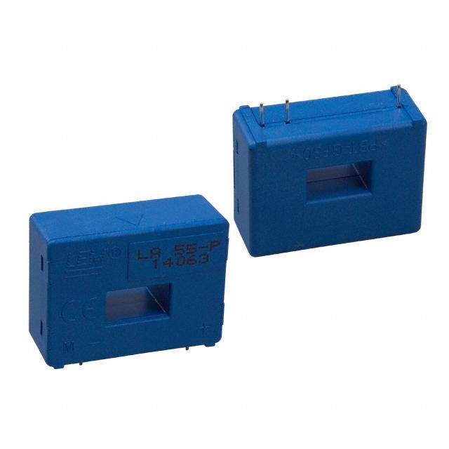
LA 55-P产品简介:
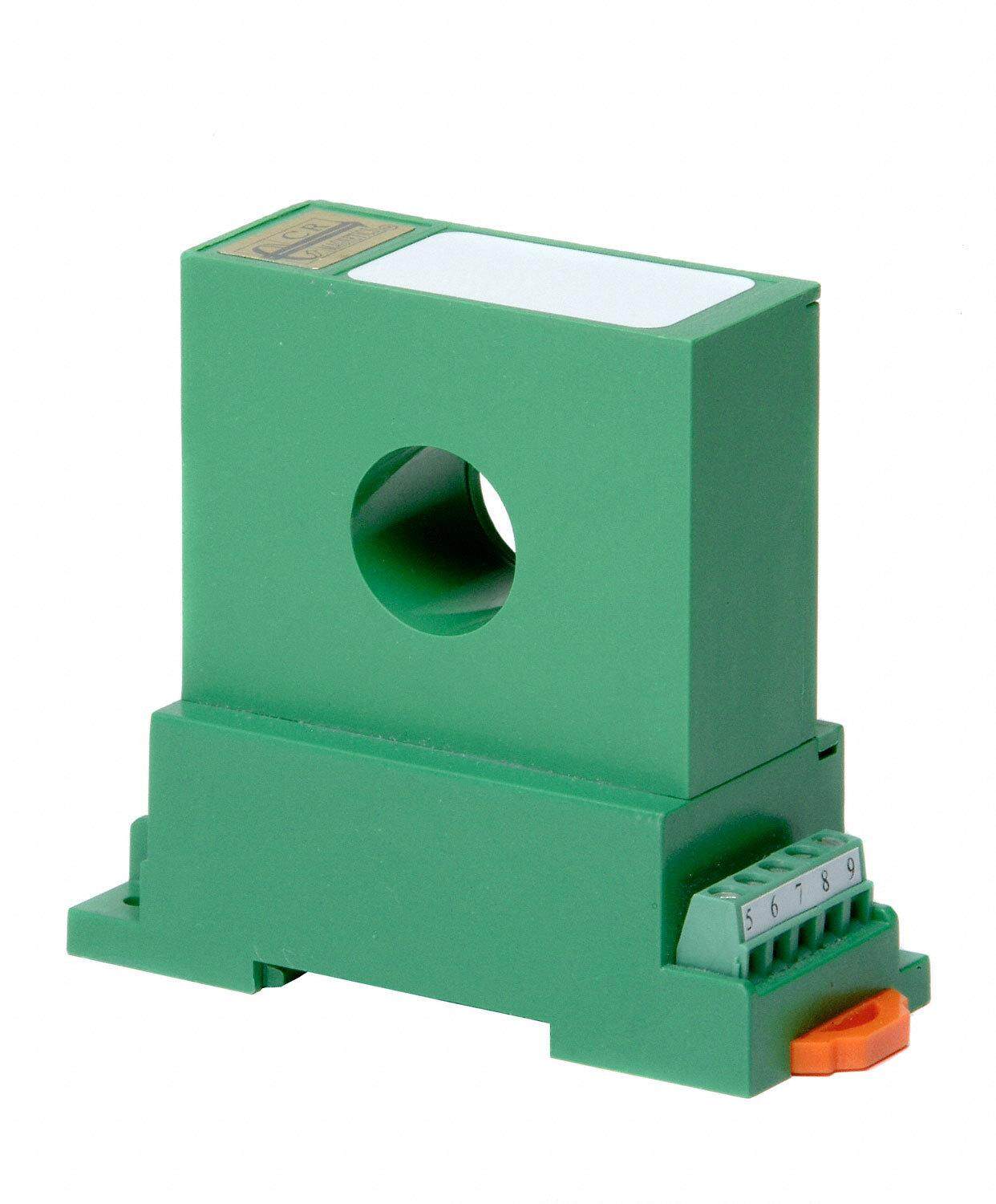
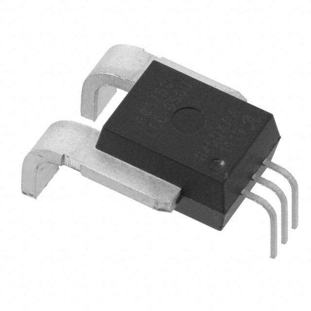
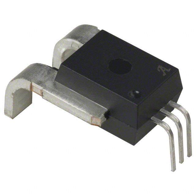
ICGOO电子元器件商城为您提供LA 55-P由LEM设计生产,在icgoo商城现货销售,并且可以通过原厂、代理商等渠道进行代购。 LA 55-P价格参考¥126.01-¥198.01。LEMLA 55-P封装/规格:电流变送器, 电流传感器 50A 1 通道 霍尔效应,闭环 双向 模块,单通式。您可以下载LA 55-P参考资料、Datasheet数据手册功能说明书,资料中有LA 55-P 详细功能的应用电路图电压和使用方法及教程。
LEM USA Inc.生产的LA 55-P电流变送器是一种高精度、隔离型的电流传感器,广泛应用于工业自动化、电力监控、能源管理以及电机驱动等领域。以下是其主要应用场景:

1. 工业自动化:
   LA 55-P可用于监测和控制生产线上的电流消耗,帮助优化设备运行效率。它能够实时检测电机、变频器和其他电气设备的电流状态,确保系统稳定运行并及时发现异常。

2. 电力监控与保护:
   在配电系统中,该变送器可以测量负载电流,提供准确的数据用于电力管理和故障诊断。通过监测电流波动,可预防过载或短路等问题,提高供电安全性。

3. 新能源领域:
   例如在风力发电、太阳能逆变器及储能系统中,LA 55-P能精确测量交流或直流电流,为能量转换和分配提供可靠依据,支持高效能源管理。

4. 楼宇自动化:
   在智能建筑中,此型号可用于空调、电梯等大功率设备的能耗监测,实现节能目标。同时,它还能协助维护人员评估设备健康状况。

5. 测试与测量:
   实验室环境中,LA 55-P适用于各种电力参数的精确测量,如谐波分析、功率因数计算等,为产品研发和质量控制提供支持。

6. 铁路交通:
   在轨道交通牵引系统中,该变送器可用于监测列车电机的工作电流,保障行车安全并延长设备寿命。

7. 电动汽车充电站:
   LA 55-P可集成到充电桩内,用于精确计量车辆充电过程中的电流值,确保计费准确且系统运行稳定。

总结来说,LA 55-P以其高精度、宽量程和优良的电气隔离性能,成为众多需要精准电流监测场合的理想选择。
| 参数 | 数值 |
| 产品目录 | |
| 描述 | SENSOR CURRENT 50A TH |
| 产品分类 | |
| 品牌 | LEM USA Inc |
| 数据手册 | |
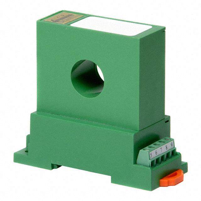
| 产品图片 |
|
| 产品型号 | LA 55-P |
| rohs | 无铅 / 符合限制有害物质指令(RoHS)规范要求 |
| 产品系列 | LA |
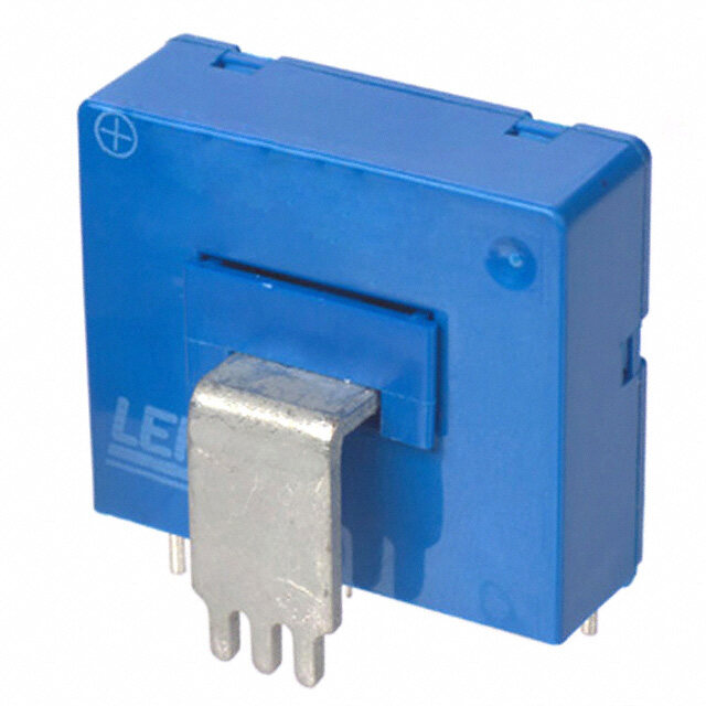
| 产品目录绘图 |
|
| 产品目录页面 | |
| 传感器类型 | 霍尔效应, 闭环 |
| 其它名称 | 398-1010 |
| 包装 | 散装 |
| 响应时间 | 1µs |
| 安装类型 | 通孔 |
| 封装/外壳 | 模块,单通式 |
| 工作温度 | -40°C ~ 85°C |
| 极化 | 双向 |
| 标准包装 | 1 |
| 灵敏度 | - |
| 用于测量 | AC/DC |
| 电压-电源 | ±12 V ~ 15 V |
| 电流-检测 | 50A |
| 电流-电源(最大值) | 60mA |
| 精度 | ±0.65% |
| 线性度 | ±0.15% |
| 输出 | 比率, 电流 |
| 通道数 | 1 |
| 频率 | DC ~ 200kHz |


- 商务部:美国ITC正式对集成电路等产品启动337调查
- 曝三星4nm工艺存在良率问题 高通将骁龙8 Gen1或转产台积电
- 太阳诱电将投资9.5亿元在常州建新厂生产MLCC 预计2023年完工
- 英特尔发布欧洲新工厂建设计划 深化IDM 2.0 战略
- 台积电先进制程称霸业界 有大客户加持明年业绩稳了
- 达到5530亿美元!SIA预计今年全球半导体销售额将创下新高
- 英特尔拟将自动驾驶子公司Mobileye上市 估值或超500亿美元
- 三星加码芯片和SET,合并消费电子和移动部门,撤换高东真等 CEO
- 三星电子宣布重大人事变动 还合并消费电子和移动部门
- 海关总署:前11个月进口集成电路产品价值2.52万亿元 增长14.8%

PDF Datasheet 数据手册内容提取
Current Transducer LA 55-P I = 50 A P N For the electronic measurement of currents: DC, AC, pulsed..., with galvanic separation between the primary circuit and the secondary circuit. Electrical data I Primary nominal RMS current 50 A P N I Primary current, measuring range 0 … ±70 A Features P M R Measuring resistance @ T = 70 °C T = 85 °C M A A R R R R ● Closed loop (compensated) M min M max M min M max with ±12 V @ ±50 A 10 100 60 95 Ω current transducer using the Hall max @ ±70 A 10 50 60 1) 60 1) Ω effect max with ±15 V @ ±50 A 50 160 135 155 Ω ● Insulating plastic case recognized max @ ±70 A 50 90 135 2) 135 2) Ω according to UL 94-V0. max I Secondary nominal RMS current 50 mA S N Advantages N /N Turns ratio 1 : 1000 P S U Supply voltage (±5 %) ±12 ... 15 V ● Excellent accuracy C I Current consumption (±2) 10 (@ ±15 V) + I mA ● Very good linearity C S ● Low temperature drift Accuracy - Dynamic performance data ● Optimized response time ● Wide frequency bandwidth ε Error @ I , T = 25 °C @ ±15 V (±5 %) ±0.65 % P N A ● No insertion losses @ ±12 … 15 V (±5 %) ±0.90 % ● High immunity to external ε Linearity error < 0.15 % L interference Typ Max ● Current overload capability. I Offset current @ I = 0, T = 25 °C ±0.2 mA O P A I Magnetic offset current 3) @ I = 0 and specified R , Applications O M P M after an overload of 3 × I ±0.3 mA P N I Temperature variation of I −25 °C … +85 °C ±0.1 ±0.6 mA ● AC variable speed drives and O T O −40 °C … −25 °C ±0.2 ±1.0 mA servo motor drives t Delay time @ 10 % of I < 500 ns ● Static converters for DC motor D 10 P N t Delay time to 90 % of I 4) < 1 µs drives D 10 P N BW Frequency bandwidth (−1 dB) DC … 200 kHz ● Battery supplied applications ● Uninterruptible Power Supplies General data (UPS) ● Switched Mode Power Supplies T Ambient operating temperature −40 … +85 °C A (SMPS) T Ambient storage temperature −40 … +90 °C S ● Power supplies for welding R Resistance of secondary winding @ T = 70 °C 80 Ω S A applications. @ T = 85 °C 85 Ω A m Mass 18 g Application domain Standards EN 50178: 1997 ● Industrial. UL 508: 2010 Notes: 1) Measuring range limited to ±60 A max 2) Measuring range limited to ±55 A max 3) Result of the coercive field of the magnetic circuit 4) For a di/dt = 200 A/µs. N° 97.13.25.000.0 Page 1/3 17September2018/version 17 LEM reserves the right to carry out modifications on its transducers, in order to improve them, without prior notice www.lem.com
Current Transducer LA 55-P Insulation coordination U RMS voltage for AC insulation test, 50 Hz/1 min 2.5 kV d U Impulse withstand voltage 1.2/50 µs 5.7 kV Ni Min d Creepage distance 5 mm Cp d Clearance 5 mm CI CTI Comparative tracking index (group I) 600 Applications examples According to EN 50178 and IEC 61010-1 standards and following conditions: ● Over voltage category OV 3 ● Pollution degree PD2 ● Non-uniform field EN 50178 IEC 61010-1 d , d , U Rated insulation voltage Nominal voltage Cp CI Ni Basic insulation 300 V 300 V Reinforced insulation 150 V 150 V Safety This transducer must be used in limited-energy secondary circuits according to IEC 61010-1. This transducer must be used in electric/electronic equipment with respect to applicable standards and safety requirements in accordance with the manufacturer’s operating instructions. Caution, risk of electrical shock When operating the transducer, certain parts of the module can carry hazardous voltage (eg. primary busbar, power supply). Ignoring this warning can lead to injury and/or cause serious damage. This transducer is a build-in device, whose conducting parts must be inaccessible after installation. A protective housing or additional shield could be used. Main supply must be able to be disconnected. Page 2/3 17September2018/version 17 LEM reserves the right to carry out modifications on its transducers, in order to improve them, without prior notice www.lem.com
Dimensions LA 55-P (in mm) d d Cl Cp I d d P Cl Cp dCl dCp IS RM U Connection I C P IP I R UC I R S M S M U U C C U UC dCl dCp C Mechanical characteristics Remarks I P ● General tolerance ±0.2 mm ● IS is positive when IP flows in the directionIS of thReM arrow. ● Primary through-hole 12.7 × 7 mm ● Temperature of the primary conductor should not exceed ● Fastening & connection of secondary 3 pins 90 °C. U 0.6 × 0.7 mm ● Installation of the transducer must be done unless C ● Recommended PCB hole 1.2 mm otherwise specified on the datasheet, according to LEUM ⌀ C Transducer Generic Mounting Rules. Please refer to LEM document N°ANE120504 available on our Web site: https://www.lem.com/en/file/3137/download/. ● Dynamic performances (di/dt and delay time) are best with a single bar completely filling the primary hole. ● In order to achieve the best magnetic coupling, the primary windings have to be wound over the top edge of the device. ● This is a standard model. For different versions (supply voltages, turns ratios, unidirectional measurements...), please contact us. Page 3/3 17September2018/version 17 LEM reserves the right to carry out modifications on its transducers, in order to improve them, without prior notice www.lem.com