ICGOO在线商城 > 集成电路(IC) > PMIC - 稳压器 - 线性 > L4995JTR
 Datasheet下载
- 型号: L4995JTR
- 制造商: STMicroelectronics
- 库位|库存: xxxx|xxxx
- 要求:
| 数量阶梯 | 香港交货 | 国内含税 |
| +xxxx | $xxxx | ¥xxxx |
查看当月历史价格
查看今年历史价格
L4995JTR产品简介:
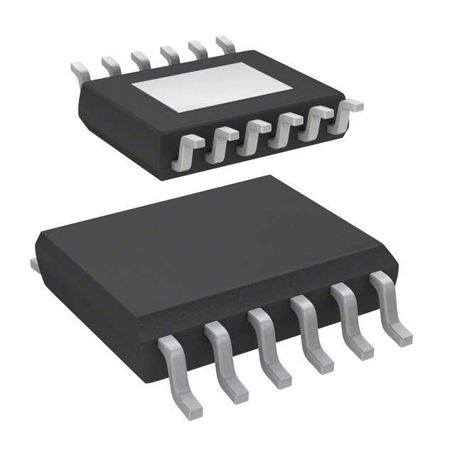
ICGOO电子元器件商城为您提供L4995JTR由STMicroelectronics设计生产,在icgoo商城现货销售,并且可以通过原厂、代理商等渠道进行代购。 L4995JTR价格参考。STMicroelectronicsL4995JTR封装/规格:PMIC - 稳压器 - 线性, Linear Voltage Regulator IC 1 Output 500mA PowerSSO-12。您可以下载L4995JTR参考资料、Datasheet数据手册功能说明书,资料中有L4995JTR 详细功能的应用电路图电压和使用方法及教程。
STMicroelectronics的L4995JTR是一款低压差线性稳压器(LDO),属于PMIC中的线性稳压器类别。该器件主要用于需要稳定低电压输出和高电源抑制比(PSRR)的应用场景。

典型应用场景包括便携式电池供电设备,如移动终端、手持仪器和可穿戴设备,因其低静态电流特性有助于延长电池续航时间。此外,L4995JTR适用于对噪声敏感的模拟电路供电,例如传感器接口、音频模块和精密测量系统,能够有效抑制输入电源噪声,提供干净稳定的输出电压。

该器件也常用于嵌入式系统中的辅助电源轨管理,为微控制器(MCU)、实时时钟(RTC)或存储器等关键组件提供可靠电源。其集成过热保护和短路保护功能,增强了系统安全性与可靠性。

L4995JTR采用紧凑型封装(如TO-252),适合空间受限的高密度PCB设计,广泛应用于工业控制、消费电子和汽车电子中的非动力总成系统(如车载信息终端)。总之,它是一款高效、稳定的电源管理解决方案,适用于对功耗、噪声和空间有较高要求的中低端功率应用场合。
| 参数 | 数值 |
| 产品目录 | 集成电路 (IC) |
| 描述 | IC REG LDO 5V 0.5A 12POWERSSO |
| 产品分类 | |
| 品牌 | STMicroelectronics |
| 数据手册 | |
| 产品图片 |
|
| 产品型号 | L4995JTR |
| rohs | 无铅 / 符合限制有害物质指令(RoHS)规范要求 |
| 产品系列 | - |
| 供应商器件封装 | PowerSSO-12 |
| 其它名称 | 497-11655-6 |
| 包装 | Digi-Reel® |
| 安装类型 | 表面贴装 |
| 封装/外壳 | PowerSSO-12 |
| 工作温度 | -40°C ~ 150°C |
| 标准包装 | 1 |
| 电压-跌落(典型值) | 0.27V @ 400mA |
| 电压-输入 | 5.6 V ~ 31 V |
| 电压-输出 | 5V |
| 电流-输出 | 500mA |
| 电流-限制(最小值) | 600mA |
| 稳压器拓扑 | 正,固定式 |
| 稳压器数 | 1 |


- 商务部:美国ITC正式对集成电路等产品启动337调查
- 曝三星4nm工艺存在良率问题 高通将骁龙8 Gen1或转产台积电
- 太阳诱电将投资9.5亿元在常州建新厂生产MLCC 预计2023年完工
- 英特尔发布欧洲新工厂建设计划 深化IDM 2.0 战略
- 台积电先进制程称霸业界 有大客户加持明年业绩稳了
- 达到5530亿美元!SIA预计今年全球半导体销售额将创下新高
- 英特尔拟将自动驾驶子公司Mobileye上市 估值或超500亿美元
- 三星加码芯片和SET,合并消费电子和移动部门,撤换高东真等 CEO
- 三星电子宣布重大人事变动 还合并消费电子和移动部门
- 海关总署:前11个月进口集成电路产品价值2.52万亿元 增长14.8%


PDF Datasheet 数据手册内容提取
L4995 Automotive 5V, 500mA low drop voltage regulator Datasheet - production data Wide temperature range (Tj = -40 °C to 150 °C) Enable input for enabling/disabling the voltage regulator PowerSSO-12 PowerSSO-24 Description Features L4995 is a family of monolithic integrated 5 V voltage regulators with a low drop voltage at currents of up to 500 mA, available in both 12 and Max DC supply voltage VS 40V 24 pin packages. Max output voltage tolerance V +/-2% o The output voltage regulating element consists of Max dropout voltage Vdp 500mV a p-channel MOS and regulation is performed Output current I 500mA regardless of input voltage transients of up to 40V. o Quiescent current Iqn 3µA(1) The high precision of the output voltage is 1. Typical value with regulator disabled obtained using a pre-trimmed reference voltage. The L4995 family is protected against short circuit AEC-Q100 qualified and overtemperature protection switches off the devices in the case of extremely high power Operating DC supply voltage dissipation. The L4995 integrates the watchdog, range 5.6 V to 31 V enable and externally programmable reset Low dropout voltage circuits. The L4995A features the externally Low quiescent current consumption programmable reset and enable. Finally the L4995R features the externally programmable Reset circuit sensing of output voltage down to reset. 1 V The combination of such features makes this Programmable reset pulse delay with external device particularly flexible and suitable to supply capacitor microprocessor systems in automotive Programmable watchdog timer with external applications. capacitor Thermal shutdown and short circuit protection Table 1. Device summary Order codes Package Tube Tape and reel PowerSSO-12 (exposed pad) L4995J - L4995AJ - L4995RJ L4995JTR - L4995AJTR - L4995RJTR PowerSSO-24 (exposed pad) L4995K - L4995AK - L4995RK L4995KTR - L4995AKTR - L4995RKTR P/N Watchdog Reset Enable L4995J - L4995K X X X L4995AJ - L4995AK - X X L4995RJ - L4995RK - X - September 2018 DS5053 Rev 15 1/37 This is information on a product in full production. www.st.com
Contents L4995 Contents 1 Block diagrams and pins descriptions . . . . . . . . . . . . . . . . . . . . . . . . . . 6 2 Electrical specifications . . . . . . . . . . . . . . . . . . . . . . . . . . . . . . . . . . . . . . 9 2.1 Absolute maximum ratings . . . . . . . . . . . . . . . . . . . . . . . . . . . . . . . . . . . . . 9 2.2 Thermal data . . . . . . . . . . . . . . . . . . . . . . . . . . . . . . . . . . . . . . . . . . . . . . 10 2.3 Electrical characteristics . . . . . . . . . . . . . . . . . . . . . . . . . . . . . . . . . . . . . . 10 2.4 Electrical characteristics curves . . . . . . . . . . . . . . . . . . . . . . . . . . . . . . . . 13 2.5 Test circuit and waveforms plot . . . . . . . . . . . . . . . . . . . . . . . . . . . . . . . . 16 2.5.1 Load regulation . . . . . . . . . . . . . . . . . . . . . . . . . . . . . . . . . . . . . . . . . . . 16 3 Application information . . . . . . . . . . . . . . . . . . . . . . . . . . . . . . . . . . . . . 18 3.1 Voltage regulator . . . . . . . . . . . . . . . . . . . . . . . . . . . . . . . . . . . . . . . . . . . 19 3.2 Reset . . . . . . . . . . . . . . . . . . . . . . . . . . . . . . . . . . . . . . . . . . . . . . . . . . . . 19 3.3 Watchdog . . . . . . . . . . . . . . . . . . . . . . . . . . . . . . . . . . . . . . . . . . . . . . . . . 20 4 Package and PCB thermal data . . . . . . . . . . . . . . . . . . . . . . . . . . . . . . . 22 4.1 PowerSSO-12 thermal data . . . . . . . . . . . . . . . . . . . . . . . . . . . . . . . . . . . 22 4.2 PowerSSO-24 thermal data . . . . . . . . . . . . . . . . . . . . . . . . . . . . . . . . . . . 25 5 Package and packing information . . . . . . . . . . . . . . . . . . . . . . . . . . . . . 28 5.1 ECOPACK® . . . . . . . . . . . . . . . . . . . . . . . . . . . . . . . . . . . . . . . . . . . . . . . . . . . . . . . . . . . . 28 5.2 PowerSSO-24 mechanical data . . . . . . . . . . . . . . . . . . . . . . . . . . . . . . . . 30 5.3 PowerSSO-12 packing information . . . . . . . . . . . . . . . . . . . . . . . . . . . . . 32 5.4 PowerSSO-24 packing information . . . . . . . . . . . . . . . . . . . . . . . . . . . . . 33 6 Revision history . . . . . . . . . . . . . . . . . . . . . . . . . . . . . . . . . . . . . . . . . . . 34 2/37 DS5053 Rev 15
L4995 List of tables List of tables Table 1. Device summary. . . . . . . . . . . . . . . . . . . . . . . . . . . . . . . . . . . . . . . . . . . . . . . . . . . . . . . . . . 1 Table 2. Pins descriptions. . . . . . . . . . . . . . . . . . . . . . . . . . . . . . . . . . . . . . . . . . . . . . . . . . . . . . . . . . 7 Table 3. Absolute maximum ratings. . . . . . . . . . . . . . . . . . . . . . . . . . . . . . . . . . . . . . . . . . . . . . . . . . 9 Table 4. Thermal data. . . . . . . . . . . . . . . . . . . . . . . . . . . . . . . . . . . . . . . . . . . . . . . . . . . . . . . . . . . . 10 Table 5. General. . . . . . . . . . . . . . . . . . . . . . . . . . . . . . . . . . . . . . . . . . . . . . . . . . . . . . . . . . . . . . . . 10 Table 6. Reset . . . . . . . . . . . . . . . . . . . . . . . . . . . . . . . . . . . . . . . . . . . . . . . . . . . . . . . . . . . . . . . . . 11 Table 7. Watchdog . . . . . . . . . . . . . . . . . . . . . . . . . . . . . . . . . . . . . . . . . . . . . . . . . . . . . . . . . . . . . . 12 Table 8. Enable. . . . . . . . . . . . . . . . . . . . . . . . . . . . . . . . . . . . . . . . . . . . . . . . . . . . . . . . . . . . . . . . . 12 Table 9. PowerSSO-12 thermal parameter . . . . . . . . . . . . . . . . . . . . . . . . . . . . . . . . . . . . . . . . . . . 24 Table 10. PowerSSO-24 thermal parameter . . . . . . . . . . . . . . . . . . . . . . . . . . . . . . . . . . . . . . . . . . . 27 Table 11. PowerSSO-12 mechanical data . . . . . . . . . . . . . . . . . . . . . . . . . . . . . . . . . . . . . . . . . . . . . 29 Table 12. PowerSSO-24 mechanical data . . . . . . . . . . . . . . . . . . . . . . . . . . . . . . . . . . . . . . . . . . . . . 31 Table 13. Document revision history . . . . . . . . . . . . . . . . . . . . . . . . . . . . . . . . . . . . . . . . . . . . . . . . . 34 DS5053 Rev 15 3/37 3
List of figures L4995 List of figures Figure 1. Block diagram of L4995 . . . . . . . . . . . . . . . . . . . . . . . . . . . . . . . . . . . . . . . . . . . . . . . . . . . . 6 Figure 2. Block diagram of L4995A . . . . . . . . . . . . . . . . . . . . . . . . . . . . . . . . . . . . . . . . . . . . . . . . . . . 6 Figure 3. Block diagram of L4995R. . . . . . . . . . . . . . . . . . . . . . . . . . . . . . . . . . . . . . . . . . . . . . . . . . . 7 Figure 4. Pins configurations (L4995) . . . . . . . . . . . . . . . . . . . . . . . . . . . . . . . . . . . . . . . . . . . . . . . . . 8 Figure 5. Output voltage vs T . . . . . . . . . . . . . . . . . . . . . . . . . . . . . . . . . . . . . . . . . . . . . . . . . . . . . . 13 j Figure 6. Output voltage vs V . . . . . . . . . . . . . . . . . . . . . . . . . . . . . . . . . . . . . . . . . . . . . . . . . . . . . . 13 S Figure 7. Drop voltage vs output current . . . . . . . . . . . . . . . . . . . . . . . . . . . . . . . . . . . . . . . . . . . . . . 13 Figure 8. Current consumption vs output current. . . . . . . . . . . . . . . . . . . . . . . . . . . . . . . . . . . . . . . . 13 Figure 9. Current consumption vs input voltage . . . . . . . . . . . . . . . . . . . . . . . . . . . . . . . . . . . . . . . . 13 Figure 10. Current limitation vs T . . . . . . . . . . . . . . . . . . . . . . . . . . . . . . . . . . . . . . . . . . . . . . . . . . . . 13 j Figure 11. Current limitation vs input voltage. . . . . . . . . . . . . . . . . . . . . . . . . . . . . . . . . . . . . . . . . . . . 14 Figure 12. Short circuit current vs input voltage. . . . . . . . . . . . . . . . . . . . . . . . . . . . . . . . . . . . . . . . . . 14 Figure 13. Output voltage vs enable voltage. . . . . . . . . . . . . . . . . . . . . . . . . . . . . . . . . . . . . . . . . . . . 14 Figure 14. V vs T. . . . . . . . . . . . . . . . . . . . . . . . . . . . . . . . . . . . . . . . . . . . . . . . . . . . . . . . . . . . 14 En_high j Figure 15. V vsT . . . . . . . . . . . . . . . . . . . . . . . . . . . . . . . . . . . . . . . . . . . . . . . . . . . . . . . . . . . 14 EN_LOW j Figure 16. V vsT . . . . . . . . . . . . . . . . . . . . . . . . . . . . . . . . . . . . . . . . . . . . . . . . . . . . . . . . . . . . . . 14 Rhth j Figure 17. V vs T . . . . . . . . . . . . . . . . . . . . . . . . . . . . . . . . . . . . . . . . . . . . . . . . . . . . . . . . . . . . . . 15 Rlth j Figure 18. V vs T . . . . . . . . . . . . . . . . . . . . . . . . . . . . . . . . . . . . . . . . . . . . . . . . . . . . . . . . . . . . . . 15 whth j Figure 19. V vs T . . . . . . . . . . . . . . . . . . . . . . . . . . . . . . . . . . . . . . . . . . . . . . . . . . . . . . . . . . . . . . 15 wlth j Figure 20. I and I vs T . . . . . . . . . . . . . . . . . . . . . . . . . . . . . . . . . . . . . . . . . . . . . . . . . . . . . . . . . 15 cr cwc j Figure 21. I and I vs T . . . . . . . . . . . . . . . . . . . . . . . . . . . . . . . . . . . . . . . . . . . . . . . . . . . . . . . . . 15 dr cwd j Figure 22. T vs T . . . . . . . . . . . . . . . . . . . . . . . . . . . . . . . . . . . . . . . . . . . . . . . . . . . . . . . . . . . . . . 15 wop j Figure 23. PSRR . . . . . . . . . . . . . . . . . . . . . . . . . . . . . . . . . . . . . . . . . . . . . . . . . . . . . . . . . . . . . . . . . 16 Figure 24. Load regulation test circuit . . . . . . . . . . . . . . . . . . . . . . . . . . . . . . . . . . . . . . . . . . . . . . . . . 16 Figure 25. Maximum load variation response . . . . . . . . . . . . . . . . . . . . . . . . . . . . . . . . . . . . . . . . . . . 17 Figure 26. L4995 application schematic . . . . . . . . . . . . . . . . . . . . . . . . . . . . . . . . . . . . . . . . . . . . . . . 18 Figure 27. Stability region . . . . . . . . . . . . . . . . . . . . . . . . . . . . . . . . . . . . . . . . . . . . . . . . . . . . . . . . . . 18 Figure 28. Behavior of output current versus regulated voltage V . . . . . . . . . . . . . . . . . . . . . . . . . . . 19 o Figure 29. Reset timing diagram . . . . . . . . . . . . . . . . . . . . . . . . . . . . . . . . . . . . . . . . . . . . . . . . . . . . . 20 Figure 30. Watchdog timing diagram. . . . . . . . . . . . . . . . . . . . . . . . . . . . . . . . . . . . . . . . . . . . . . . . . . 21 Figure 31. PowerSSO-12 PC board. . . . . . . . . . . . . . . . . . . . . . . . . . . . . . . . . . . . . . . . . . . . . . . . . . . 22 Figure 32. Rthj-amb vs PCB copper area in open box free air condition . . . . . . . . . . . . . . . . . . . . . . 22 Figure 33. PowerSSO-12 thermal impedance junction ambient single pulse . . . . . . . . . . . . . . . . . . . 23 Figure 34. Thermal fitting model of Vreg in PowerSSO-12 . . . . . . . . . . . . . . . . . . . . . . . . . . . . . . . . . 23 Figure 35. PowerSSO-24 PC board. . . . . . . . . . . . . . . . . . . . . . . . . . . . . . . . . . . . . . . . . . . . . . . . . . . 25 Figure 36. Rthj-amb vs PCB copper area in open box free air condition . . . . . . . . . . . . . . . . . . . . . . 25 Figure 37. PowerSSO-24 thermal impedance junction ambient single pulse . . . . . . . . . . . . . . . . . . . 26 Figure 38. Thermal fitting model of V in PowerSSO-24 . . . . . . . . . . . . . . . . . . . . . . . . . . . . . . . . . 26 reg Figure 39. PowerSSO-12 package dimensions. . . . . . . . . . . . . . . . . . . . . . . . . . . . . . . . . . . . . . . . . . 28 Figure 40. PowerSSO-24 package dimensions. . . . . . . . . . . . . . . . . . . . . . . . . . . . . . . . . . . . . . . . . . 30 Figure 41. PowerSSO-12 tube shipment (no suffix) . . . . . . . . . . . . . . . . . . . . . . . . . . . . . . . . . . . . . . 32 Figure 42. PowerSSO-12 tape and reel shipment (suffix “TR”). . . . . . . . . . . . . . . . . . . . . . . . . . . . . . 32 Figure 43. PowerSS0-24 tube shipment (no suffix). . . . . . . . . . . . . . . . . . . . . . . . . . . . . . . . . . . . . . . 33 Figure 44. PowerSSO-24 tape and reel shipment (suffix “TR”). . . . . . . . . . . . . . . . . . . . . . . . . . . . . . 33 4/37 DS5053 Rev 15
Block diagrams and pins descriptions L4995 1 Block diagrams and pins descriptions Figure 1. Block diagram of L4995 (cid:44)(cid:86) (cid:57)(cid:86) (cid:57)(cid:82) (cid:44)(cid:82) (cid:57)(cid:82)(cid:86) (cid:57) (cid:54)(cid:87)(cid:68)(cid:85)(cid:87)(cid:3)(cid:88)(cid:83) (cid:54) (cid:20)(cid:17)(cid:21)(cid:24)(cid:57) (cid:44) (cid:40)(cid:81) (cid:57)(cid:82)(cid:79)(cid:87)(cid:68)(cid:74)(cid:72) (cid:40)(cid:81) (cid:53)(cid:72)(cid:73)(cid:72)(cid:85)(cid:72)(cid:81)(cid:70)(cid:72) (cid:20)(cid:19)(cid:19)(cid:80)(cid:57) (cid:14)(cid:66) (cid:57)(cid:82) (cid:57)(cid:40)(cid:81) (cid:57)(cid:70)(cid:90) (cid:44)(cid:70)(cid:90) (cid:57)(cid:70)(cid:90) (cid:53)(cid:72)(cid:86) (cid:58)(cid:76) (cid:90)(cid:68)(cid:87)(cid:70)(cid:75)(cid:71)(cid:82)(cid:74) (cid:57)(cid:90)(cid:76) (cid:57) (cid:47)(cid:82)(cid:90)(cid:3)(cid:57)(cid:82)(cid:79)(cid:87)(cid:68)(cid:74)(cid:72) (cid:53)(cid:72)(cid:86) (cid:53)(cid:72)(cid:86)(cid:72)(cid:87) (cid:57)(cid:70)(cid:85) (cid:42)(cid:49)(cid:39) (cid:57)(cid:70)(cid:85) (cid:40)(cid:34)(cid:49)(cid:40)(cid:46)(cid:52)(cid:17)(cid:17)(cid:17)(cid:22)(cid:18) Figure 2. Block diagram of L4995A (cid:44)(cid:86) (cid:57)(cid:86) (cid:57)(cid:82) (cid:44)(cid:82) (cid:57)(cid:82)(cid:86) (cid:57) (cid:54)(cid:87)(cid:68)(cid:85)(cid:87)(cid:3)(cid:88)(cid:83) (cid:54) (cid:20)(cid:17)(cid:21)(cid:24)(cid:57) (cid:44) (cid:40)(cid:81) (cid:57)(cid:82)(cid:79)(cid:87)(cid:68)(cid:74)(cid:72) (cid:40)(cid:81) (cid:53)(cid:72)(cid:73)(cid:72)(cid:85)(cid:72)(cid:81)(cid:70)(cid:72) (cid:20)(cid:19)(cid:19)(cid:80)(cid:57) (cid:14)(cid:66) (cid:57)(cid:82) (cid:57)(cid:40)(cid:81) (cid:53)(cid:72)(cid:86) (cid:57) (cid:47)(cid:82)(cid:90)(cid:3)(cid:57)(cid:82)(cid:79)(cid:87)(cid:68)(cid:74)(cid:72) (cid:53)(cid:72)(cid:86) (cid:53)(cid:72)(cid:86)(cid:72)(cid:87) (cid:57)(cid:70)(cid:85) (cid:42)(cid:49)(cid:39) (cid:57)(cid:70)(cid:85) (cid:42)(cid:36)(cid:51)(cid:42)(cid:48)(cid:54)(cid:19)(cid:19)(cid:19)(cid:24)(cid:21) 6/37 DS5053 Rev 15
L4995 Block diagrams and pins descriptions Figure 3. Block diagram of L4995R (cid:44)(cid:86) (cid:57)(cid:86) (cid:57)(cid:82) (cid:44)(cid:82) (cid:57)(cid:82)(cid:86) (cid:57) (cid:54)(cid:87)(cid:68)(cid:85)(cid:87)(cid:3)(cid:88)(cid:83) (cid:54) (cid:20)(cid:17)(cid:21)(cid:24)(cid:57) (cid:57)(cid:82)(cid:79)(cid:87)(cid:68)(cid:74)(cid:72) (cid:53)(cid:72)(cid:73)(cid:72)(cid:85)(cid:72)(cid:81)(cid:70)(cid:72) (cid:20)(cid:19)(cid:19)(cid:80)(cid:57) (cid:14)(cid:66) (cid:57)(cid:82) (cid:57)(cid:40)(cid:81) (cid:53)(cid:72)(cid:86) (cid:57) (cid:47)(cid:82)(cid:90)(cid:3)(cid:57)(cid:82)(cid:79)(cid:87)(cid:68)(cid:74)(cid:72) (cid:53)(cid:72)(cid:86) (cid:53)(cid:72)(cid:86)(cid:72)(cid:87) (cid:57)(cid:70)(cid:85) (cid:42)(cid:49)(cid:39) (cid:57)(cid:70)(cid:85) (cid:42)(cid:36)(cid:51)(cid:42)(cid:48)(cid:54)(cid:19)(cid:19)(cid:19)(cid:24)(cid:22) (cid:3)(cid:3)(cid:3)(cid:3)(cid:3)(cid:3)(cid:3)(cid:3)(cid:3) Table 2. Pins descriptions Pin PowerSSO-12 PowerSSO-24 Function name pin # pin # Enable input (L4995 and L4996A only, otherwise not connected). En 1 13, 14, 15 If high regulator, watchdog and reset are operating. If low regulator, watchdog and reset are shutdown. Connect to Vs if not used. NC 2, 4, 8 3, 5, 6, 9, 11 Not connected. GND 3 16, 17, 18 Ground reference. Substrate of the chip: connect the pins or the TAB to - TAB TAB, 1, 12 GND. Reset output. Res 5 19, 20, 21 It is pulled down when output voltage goes below Vo_th or frequency at Wi is too low. Leave floating if not used. Reset timing adjust. Vcr 6 22, 23, 24 A capacitor between Vcr pin and GND. Sets the reset delay time (trd). Leave floating if Reset is not used. Watchdog timer adjust (L4995 only, otherwise not connected). V 7 2 cw A capacitor between V pin and GND. Sets the time cw response of the watchdog monitor. DS5053 Rev 15 7/37 36
Block diagrams and pins descriptions L4995 Table 2. Pins descriptions (continued) Pin PowerSSO-12 PowerSSO-24 Function name pin # pin # Watchdog input (L4995 only, otherwise not connected). Wi 9 4 If the frequency at this input pin is too low, the Reset output is activated. V 10 7 Regulator voltage output sensing. os 5 voltage regulator output. Vo 11 8 Block to ground with a capacitor >100nF (needed for regulator stability). Supply voltage. VS 12 10 Block to ground directly at VS pin with a ceramic capacitor (e.g. 200nF). Figure 4. Pins configurations (L4995) (cid:86)(cid:88)(cid:69)(cid:86)(cid:87)(cid:85)(cid:68)(cid:87)(cid:72) (cid:55)(cid:36)(cid:37)(cid:3)(cid:32)(cid:3)(cid:86)(cid:88)(cid:69)(cid:86)(cid:87)(cid:85)(cid:68)(cid:87)(cid:72) (cid:86)(cid:88)(cid:69)(cid:86)(cid:87)(cid:85)(cid:68)(cid:87)(cid:72) (cid:55)(cid:36)(cid:37)(cid:3)(cid:32)(cid:3)(cid:86)(cid:88)(cid:69)(cid:86)(cid:87)(cid:85)(cid:68)(cid:87)(cid:72) (cid:42)(cid:36)(cid:51)(cid:42)(cid:48)(cid:54)(cid:19)(cid:19)(cid:19)(cid:24)(cid:23) 8/37 DS5053 Rev 15
L4995 Electrical specifications 2 Electrical specifications 2.1 Absolute maximum ratings Stressing the device above the rating listed in the “Absolute maximum ratings” table may cause permanent damage to the device. These are stress ratings only and operation of the device at these or any other conditions above those indicated in the Operating sections of this specification is not implied. Exposure to Absolute Maximum Rating conditions for extended periods may affect device reliability. Refer also to the STMicroelectronics SURE Program and other relevant quality documents. Table 3. Absolute maximum ratings Symbol Parameter Value Unit V DC supply voltage - 0.3 to 40 V Vsdc I Input current Internally limited Vsdc V (1) DC output voltage - 0.3 to 6 V Vo I DC output current Internally limited Vo V Watchdog input voltage -0.3 to V + 0.3 V Wi Vo V R output voltage -0.3 to V + 0.3 V od es Vo I R output current Internally limited od es V V voltage - 0.3 to V + 0.3 V cr cr Vo V Watchdog delay voltage - 0.3 to V + 0.3 V cw Vo V Enable input - 0.3 to V +0.3 V En Vsdc T Junction temperature - 40 to 150 C j V ESD voltage level (HBM-MIL STD 883C) ± 2 kV ESD V ESD voltage level (CDM AEC-Q100-011) 750 V ESD 1. Using the typical application schematic with Cout= 10 µF and Iout=0 A, when the regulator is switched-on, an overshoot exceeding 6 V could occur.This behavior does not impact the reliability of the regulator. DS5053 Rev 15 9/37 36
Electrical specifications L4995 2.2 Thermal data For details, please refer to Section 4.1: PowerSSO-12 thermal data and Section 4.2: PowerSSO-24 thermal data. mm Table 4. Thermal data(1) Symbol Parameter Value Unit Thermal resistance Junction to Case: R PowerSSO-12 5 °K/W thj-case PowerSSO-24 4 °K/W Thermal resistance Junction to Ambient: R PowerSSO-12 52 °K/W thj-amb PowerSSO-24 38 °K/W 1. The values quoted are for PCB 77mm x 86mm x 1.6mm, FR4, double layer; Copper thickness 0.070mm Copper area 3cm2 Thermal Vias, Thermal vias separation 1.2 mm, Thermal via diameter 0.3 mm +/- 0.08 mm, Cu thickness on vias 0.025 mm. 2.3 Electrical characteristics Values specified in this section are for V = 5.6V to 31V, T = -40 °C to +150 °C unless s j otherwise stated. Table 5. General Pin Symbol Parameter Test condition Min. Typ. Max. Unit V = 5.6 to 31V V V Output voltage S 4.9 5.00 5.1 V o o_ref I = 0 to 500mA o V I Short circuit current V = 13.5V (1) 550 800 1050 mA o short S V I (2) Output current limitation V = 13.5V (1) 600 900 1250 mA o lim S V = 5.6 to 31V V , V V Line regulation voltage S 25 mV S o line I = 0 to 500mA o V V Load regulation voltage I = 0 to 500mA 25 mV o load o V , V V (3) Drop voltage I = 400mA 270 500 mV S o dp o V , V SVR Ripple rejection f = 100 Hz (4) 55 dB S o r Current consumption with V = 13.5V, V , V I S 3 10 µA S o qs regulator disabled E = low n Current consumption V = 13.5V, V , V I S 90 160 µA S o qn_1 with regulator enabled I < 1mA, o Current consumption V = 13.5V, V , V I S 290 400 µA S o qn_50 with regulator enabled I = 50mA, o 10/37 DS5053 Rev 15
L4995 Electrical specifications Table 5. General (continued) Pin Symbol Parameter Test condition Min. Typ. Max. Unit Current consumption V = 13.5V, V , V I S 740 1000 µA S o qn_150 with regulator enabled I = 150mA, o Current consumption V = 13.5V, V , V I S 1 1.4 mA S o qn_250 with regulator enabled I = 250mA, o Current consumption V = 13.5V, V , V I S 2.1 2.7 mA S o qn_500 with regulator enabled I = 500mA, o Thermal protection T 150 190 °C w temperature Thermal protection T 10 °C w_hy temperature hysteresis 1. See Figure 28. 2. Measured output current when the output voltage has dropped 100mV from its nominal value obtained at Vs=13.5V and I = 250mA. o 3. Vs-V measured when the output voltage has dropped 100mV from its nominal value obtained at Vs=13.5V o and I = 250mA. o 4. Guaranteed by design. Table 6. Reset Pin Symbol Parameter Test condition Min. Typ. Max. Unit R = 5k to V , R V Reset output low voltage ext o 0.4 V es res_l V > 1V o Reset output high leakage R I V = 5V 1 µA es Res_lkg current Res Pull up internal resistance R R 10 20 40 k es Res (versus V ) o V out of regulation V = 5.6 to 31V below R V o S 6% 8% 10% es o_th threshold Io = 1 to 500mA Vo_ref Reset delay circuit low V V V = 13.5V 10% 13% 16% V cr Rlth threshold S o_ref Reset delay circuit high V V V =13.5V 44% 47% 50% V cr Rhth threshold S o_ref V I Charge current V = 13.5V 8 15 30 µA cr cr S V I Discharge current V = 13.5V 8 15 30 µA cr dr S R T Reset reaction time(1) V = V -100mV 100 250 700 µs es rr o o_th V = 13.5V, R T Reset delay time S 12 33 73 ms es rd C = 47nF tr 1. When V becomes lower than 4V, the reset reaction time decreases down to 2µs assuring a faster reset o condition in this particular case. DS5053 Rev 15 11/37 36
Electrical specifications L4995 Table 7. Watchdog Pin Symbol Parameter Test condition Min. Typ. Max. Unit W Vih Input high voltage V = 13.5V 3.5 V i S W Vil Input low voltage V = 13.5V 1.5 V i S W Vih Input hysteresis V = 13.5V 500 mV i S V = 13.5V W I Pull down current S 6 10 µA i wi V = 3.5V wi V V Low threshold V = 13.5V 10% 13% 16% V cw wlth S o_ref V V High threshold V = 13.5V 44% 47% 50% V cw whth S o_ref V = 13.5V, V I Charge current S 5 10 20 µA cw cwc V = 0.1V cw V = 13.5V, V I Discharge current S 1.25 2.5 5 µA cw cwd V = 2.5V cw V = 13.5V, V T Watchdog period S 20 40 80 ms cw wop C = 47nF tw V = 13.5V, R t Watchdog output low time S 4 8 16 ms es wol C = 47nF tw Table 8. Enable Pin Symbol Parameter Test condition Min. Typ. Max. Unit E V E input low voltage 1 V n En_low n E V E input high voltage 3 V n En_high n E V E input hysteresis 830 mV n En_hyst n E I Pull down current V = 13.5V 10 18 µA n En S 12/37 DS5053 Rev 15
L4995 Electrical specifications 2.4 Electrical characteristics curves Figure 5. Output voltage vs T Figure 6. Output voltage vs V j S Figure 7. Drop voltage vs output current Figure 8. Current consumption vs output current Figure 9. Current consumption vs input voltage Figure 10. Current limitation vs T j (cid:3)(cid:3)(cid:3)(cid:3)(cid:3)(cid:3)(cid:3)(cid:3)(cid:3) DS5053 Rev 15 13/37 36
Electrical specifications L4995 Figure 11. Current limitation vs input voltage Figure 12. Short circuit current vs input voltage (cid:44)(cid:86)(cid:75)(cid:82)(cid:85)(cid:87)(cid:3)(cid:11)(cid:80)(cid:36)(cid:3)(cid:12) (cid:20)(cid:19)(cid:19)(cid:19) (cid:28)(cid:24)(cid:19) (cid:28)(cid:19)(cid:19) (cid:55)(cid:77)(cid:3)(cid:32)(cid:3)(cid:3)(cid:21)(cid:24)(cid:3)(cid:131)(cid:38) (cid:27)(cid:24)(cid:19) (cid:27)(cid:19)(cid:19) (cid:26)(cid:24)(cid:19) (cid:55)(cid:77)(cid:3)(cid:32)(cid:3)(cid:20)(cid:24)(cid:19)(cid:3)(cid:131)(cid:38)(cid:3) (cid:26)(cid:19)(cid:19) (cid:25)(cid:24)(cid:19) (cid:25)(cid:19)(cid:19) (cid:24)(cid:24)(cid:19) (cid:24)(cid:19)(cid:19) (cid:19) (cid:24) (cid:20)(cid:19) (cid:20)(cid:24) (cid:21)(cid:19) (cid:21)(cid:24) (cid:22)(cid:19) (cid:22)(cid:24) (cid:57)(cid:86)(cid:3)(cid:11)(cid:57)(cid:3)(cid:12) (cid:42)(cid:36)(cid:51)(cid:42)(cid:48)(cid:54)(cid:19)(cid:19)(cid:19)(cid:25)(cid:21) Figure 13. Output voltage vs enable voltage Figure 14. V vs T En_high j (cid:3)(cid:3)(cid:3)(cid:3)(cid:3)(cid:3)(cid:3)(cid:3)(cid:3) (cid:57)(cid:72)(cid:81)(cid:66)(cid:75)(cid:76)(cid:74)(cid:75)(cid:3)(cid:11)(cid:57)(cid:12) (cid:25)(cid:15)(cid:19) (cid:22) (cid:21)(cid:15)(cid:28) (cid:24)(cid:15)(cid:19) (cid:21)(cid:15)(cid:27) (cid:57)(cid:86)(cid:32)(cid:3)(cid:24)(cid:17)(cid:25)(cid:57)(cid:3)(cid:87)(cid:82)(cid:3)(cid:22)(cid:20)(cid:57) (cid:23)(cid:15)(cid:19) (cid:21)(cid:15)(cid:26) (cid:57)(cid:12) (cid:21)(cid:15)(cid:25) (cid:82)(cid:3)(cid:11)(cid:22)(cid:15)(cid:19) (cid:21)(cid:15)(cid:24) (cid:57) (cid:21)(cid:15)(cid:23) (cid:21)(cid:15)(cid:19) (cid:21)(cid:15)(cid:22) (cid:20)(cid:15)(cid:19) (cid:21)(cid:15)(cid:21) (cid:21)(cid:15)(cid:20) (cid:19)(cid:15)(cid:19) (cid:21) (cid:19)(cid:15)(cid:19) (cid:19)(cid:15)(cid:27) (cid:20)(cid:15)(cid:23) (cid:20)(cid:15)(cid:26) (cid:21)(cid:15)(cid:19) (cid:21)(cid:15)(cid:22) (cid:21)(cid:15)(cid:25) (cid:21)(cid:15)(cid:28) (cid:24)(cid:15)(cid:19) (cid:16)(cid:24)(cid:19) (cid:16)(cid:21)(cid:24) (cid:19) (cid:21)(cid:24) (cid:24)(cid:19) (cid:26)(cid:24) (cid:20)(cid:19)(cid:19) (cid:20)(cid:21)(cid:24) (cid:20)(cid:24)(cid:19) (cid:57)(cid:72)(cid:81)(cid:3)(cid:11)(cid:57)(cid:12) (cid:55)(cid:77)(cid:11)(cid:131)(cid:38)(cid:3)(cid:12) (cid:42)(cid:36)(cid:51)(cid:42)(cid:48)(cid:54)(cid:19)(cid:19)(cid:19)(cid:25)(cid:22) (cid:42)(cid:36)(cid:51)(cid:42)(cid:48)(cid:54)(cid:19)(cid:19)(cid:19)(cid:25)(cid:23) Figure 15. V vsT Figure 16. V vsT EN_LOW j Rhth j (cid:57)(cid:72)(cid:81)(cid:66)(cid:79)(cid:82)(cid:90)(cid:3)(cid:11)(cid:57)(cid:12) (cid:57)(cid:85)(cid:75)(cid:87)(cid:75)(cid:3)(cid:11)(cid:8)(cid:3)(cid:57)(cid:82)(cid:66)(cid:85)(cid:72)(cid:73)(cid:3)(cid:12) (cid:21) (cid:27)(cid:19) (cid:57)(cid:86)(cid:32)(cid:3)(cid:24)(cid:17)(cid:25)(cid:57)(cid:3)(cid:87)(cid:82)(cid:3)(cid:22)(cid:20)(cid:57) (cid:20)(cid:15)(cid:28) (cid:26)(cid:19) (cid:20)(cid:15)(cid:27) (cid:57)(cid:86)(cid:32)(cid:3)(cid:24)(cid:17)(cid:25)(cid:57)(cid:3)(cid:87)(cid:82)(cid:3)(cid:22)(cid:20)(cid:57) (cid:25)(cid:19) (cid:20)(cid:15)(cid:26) (cid:24)(cid:19) (cid:20)(cid:15)(cid:25) (cid:23)(cid:19) (cid:20)(cid:15)(cid:24) (cid:22)(cid:19) (cid:21)(cid:19) (cid:20)(cid:15)(cid:23) (cid:16)(cid:24)(cid:19) (cid:16)(cid:21)(cid:24) (cid:19) (cid:21)(cid:24) (cid:24)(cid:19) (cid:26)(cid:24) (cid:20)(cid:19)(cid:19) (cid:20)(cid:21)(cid:24) (cid:20)(cid:24)(cid:19) (cid:16)(cid:24)(cid:19) (cid:16)(cid:21)(cid:24) (cid:19) (cid:21)(cid:24) (cid:24)(cid:19) (cid:26)(cid:24) (cid:20)(cid:19)(cid:19) (cid:20)(cid:21)(cid:24) (cid:20)(cid:24)(cid:19) (cid:55)(cid:77)(cid:11)(cid:131)(cid:38)(cid:3)(cid:12) (cid:55)(cid:77)(cid:11)(cid:131)(cid:38)(cid:3)(cid:12) (cid:42)(cid:36)(cid:51)(cid:42)(cid:48)(cid:54)(cid:19)(cid:19)(cid:19)(cid:25)(cid:24) (cid:42)(cid:36)(cid:51)(cid:42)(cid:48)(cid:54)(cid:19)(cid:19)(cid:19)(cid:25)(cid:25) 14/37 DS5053 Rev 15
L4995 Electrical specifications Figure 17. V vs T Figure 18. V vs T Rlth j whth j (cid:57)(cid:85)(cid:79)(cid:87)(cid:75)(cid:3)(cid:11)(cid:8)(cid:3)(cid:57)(cid:82)(cid:66)(cid:85)(cid:72)(cid:73)(cid:12) (cid:57)(cid:90)(cid:75)(cid:87)(cid:75)(cid:3)(cid:11)(cid:8)(cid:3)(cid:57)(cid:82)(cid:66)(cid:85)(cid:72)(cid:73)(cid:3)(cid:12) (cid:24)(cid:19) (cid:27)(cid:19) (cid:57)(cid:86)(cid:32)(cid:3)(cid:24)(cid:17)(cid:25)(cid:57)(cid:3)(cid:87)(cid:82)(cid:3)(cid:22)(cid:20)(cid:57) (cid:26)(cid:19) (cid:23)(cid:19) (cid:3)(cid:3)(cid:3)(cid:3)(cid:57)(cid:86)(cid:32)(cid:3)(cid:24)(cid:17)(cid:25)(cid:57)(cid:3)(cid:87)(cid:82)(cid:3)(cid:22)(cid:20)(cid:57)(cid:3)(cid:3)(cid:3) (cid:25)(cid:19) (cid:22)(cid:19) (cid:24)(cid:19) (cid:21)(cid:19) (cid:23)(cid:19) (cid:20)(cid:19) (cid:22)(cid:19) (cid:19) (cid:21)(cid:19) (cid:16)(cid:24)(cid:19) (cid:16)(cid:21)(cid:24) (cid:19) (cid:21)(cid:24) (cid:24)(cid:19) (cid:26)(cid:24) (cid:20)(cid:19)(cid:19) (cid:20)(cid:21)(cid:24) (cid:20)(cid:24)(cid:19) (cid:16)(cid:24)(cid:19) (cid:16)(cid:21)(cid:24) (cid:19) (cid:21)(cid:24) (cid:24)(cid:19) (cid:26)(cid:24) (cid:20)(cid:19)(cid:19) (cid:20)(cid:21)(cid:24) (cid:20)(cid:24)(cid:19) (cid:55)(cid:77)(cid:11)(cid:131)(cid:38)(cid:3)(cid:12) (cid:55)(cid:77)(cid:11)(cid:131)(cid:38)(cid:3)(cid:12) (cid:42)(cid:36)(cid:51)(cid:42)(cid:48)(cid:54)(cid:19)(cid:19)(cid:19)(cid:25)(cid:26) (cid:42)(cid:36)(cid:51)(cid:42)(cid:48)(cid:54)(cid:19)(cid:19)(cid:19)(cid:25)(cid:27) Figure 19. V vs T Figure 20. I and I vs T wlth j cr cwc j (cid:44)(cid:70)(cid:85)(cid:3)(cid:9)(cid:3)(cid:44)(cid:70)(cid:90)(cid:70)(cid:3)(cid:11)(cid:151)(cid:36)(cid:12) (cid:57)(cid:90)(cid:79)(cid:87)(cid:75)(cid:3)(cid:11)(cid:8)(cid:3)(cid:57)(cid:82)(cid:66)(cid:85)(cid:72)(cid:73)(cid:12) (cid:21)(cid:19) (cid:24)(cid:19) (cid:20)(cid:27) (cid:3)(cid:3)(cid:3)(cid:3)(cid:57)(cid:86)(cid:32)(cid:3)(cid:24)(cid:17)(cid:25)(cid:57)(cid:3)(cid:87)(cid:82)(cid:3)(cid:22)(cid:20)(cid:57) (cid:57)(cid:70)(cid:90)(cid:32)(cid:3)(cid:19)(cid:17)(cid:20)(cid:57)(cid:3)(cid:3)(cid:3) (cid:23)(cid:19) (cid:3)(cid:3)(cid:3)(cid:3)(cid:57)(cid:86)(cid:32)(cid:3)(cid:24)(cid:17)(cid:25)(cid:57)(cid:3)(cid:87)(cid:82)(cid:3)(cid:22)(cid:20)(cid:57)(cid:3)(cid:3)(cid:3) (cid:20)(cid:25) (cid:44)(cid:70)(cid:85)(cid:3)(cid:3)(cid:3) (cid:22)(cid:19) (cid:20)(cid:23) (cid:20)(cid:21) (cid:21)(cid:19) (cid:44)(cid:70)(cid:90)(cid:70)(cid:3)(cid:3)(cid:3) (cid:20)(cid:19) (cid:20)(cid:19) (cid:27) (cid:25) (cid:19) (cid:16)(cid:24)(cid:19) (cid:16)(cid:21)(cid:24) (cid:19) (cid:21)(cid:24) (cid:24)(cid:19) (cid:26)(cid:24) (cid:20)(cid:19)(cid:19) (cid:20)(cid:21)(cid:24) (cid:20)(cid:24)(cid:19) (cid:16)(cid:24)(cid:19) (cid:16)(cid:21)(cid:24) (cid:19) (cid:21)(cid:24) (cid:24)(cid:19) (cid:26)(cid:24) (cid:20)(cid:19)(cid:19) (cid:20)(cid:21)(cid:24) (cid:20)(cid:24)(cid:19) (cid:55)(cid:77)(cid:11)(cid:131)(cid:38)(cid:3)(cid:12) (cid:42)(cid:36)(cid:51)(cid:42)(cid:48)(cid:54)(cid:19)(cid:19)(cid:19)(cid:25)(cid:28) (cid:55)(cid:77)(cid:11)(cid:131)(cid:38)(cid:3)(cid:12) (cid:42)(cid:36)(cid:51)(cid:42)(cid:48)(cid:54)(cid:19)(cid:19)(cid:19)(cid:26)(cid:19) Figure 21. I and I vs T Figure 22. T vs T dr cwd j wop j (cid:55)(cid:90)(cid:82)(cid:83)(cid:3)(cid:11)(cid:80)(cid:86)(cid:12) (cid:44)(cid:71)(cid:85)(cid:3)(cid:9)(cid:3)(cid:44)(cid:70)(cid:90)(cid:71)(cid:3)(cid:11)(cid:151)(cid:36)(cid:12) (cid:27)(cid:19) (cid:21)(cid:19) (cid:20)(cid:27) (cid:3)(cid:3)(cid:3)(cid:3)(cid:57)(cid:86)(cid:32)(cid:3)(cid:24)(cid:17)(cid:25)(cid:57)(cid:3)(cid:87)(cid:82)(cid:3)(cid:22)(cid:20)(cid:57) (cid:26)(cid:19) (cid:57)(cid:70)(cid:90)(cid:3)(cid:32)(cid:3)(cid:21)(cid:17)(cid:24)(cid:57)(cid:3)(cid:3)(cid:3) (cid:20)(cid:25) (cid:44)(cid:71)(cid:85)(cid:3)(cid:3)(cid:3) (cid:57)(cid:86)(cid:32)(cid:3)(cid:24)(cid:17)(cid:25)(cid:57)(cid:3)(cid:87)(cid:82)(cid:3)(cid:22)(cid:20)(cid:57) (cid:20)(cid:23) (cid:25)(cid:19) (cid:38)(cid:87)(cid:90)(cid:32)(cid:3)(cid:23)(cid:26)(cid:81)(cid:41) (cid:20)(cid:21) (cid:20)(cid:19) (cid:24)(cid:19) (cid:27) (cid:23)(cid:19) (cid:25) (cid:23) (cid:44)(cid:70)(cid:90)(cid:71)(cid:3)(cid:3)(cid:3) (cid:22)(cid:19) (cid:21) (cid:19) (cid:21)(cid:19) (cid:16)(cid:24)(cid:19) (cid:16)(cid:21)(cid:24) (cid:19) (cid:21)(cid:24) (cid:24)(cid:19) (cid:26)(cid:24) (cid:20)(cid:19)(cid:19) (cid:20)(cid:21)(cid:24) (cid:20)(cid:24)(cid:19) (cid:16)(cid:24)(cid:19) (cid:16)(cid:21)(cid:24) (cid:19) (cid:21)(cid:24) (cid:24)(cid:19) (cid:26)(cid:24) (cid:20)(cid:19)(cid:19) (cid:20)(cid:21)(cid:24) (cid:20)(cid:24)(cid:19) (cid:55)(cid:77)(cid:11)(cid:131)(cid:38)(cid:3)(cid:12) (cid:55)(cid:77)(cid:11)(cid:131)(cid:38)(cid:3)(cid:12) (cid:42)(cid:36)(cid:51)(cid:42)(cid:48)(cid:54)(cid:19)(cid:19)(cid:19)(cid:26)(cid:20) (cid:42)(cid:36)(cid:51)(cid:42)(cid:48)(cid:54)(cid:19)(cid:19)(cid:19)(cid:26)(cid:21) DS5053 Rev 15 15/37 36
Electrical specifications L4995 Figure 23. PSRR C0== 44..77 µµFF PSRR [dB] 80,00 70,00 60,00 50,00 40,00 30,00 20,00 10,00 0,00 0,10 1,00 10,00 11000,00 1000,00 1000000,00 FREQUENCY [KHz] GAPGMS00073 2.5 Test circuit and waveforms plot 2.5.1 Load regulation Figure 24. Load regulation test circuit (cid:20)(cid:19) (cid:42)(cid:36)(cid:51)(cid:42)(cid:48)(cid:54)(cid:19)(cid:19)(cid:19)(cid:26)(cid:23) 16/37 DS5053 Rev 15
L4995 Electrical specifications Figure 25. Maximum load variation response V0 [1V /div] I0 [200mA /div] 0,00E+00 5,00E-05 1,00E-04 1,50E-04 2,00E-04 2,50E-04 3,00E-04 3,50E-04 4,00E-04 Time [s] GAPGMS00081 DS5053 Rev 15 17/37 36
Application information L4995 3 Application information Figure 26. L4995 application schematic (cid:57)(cid:57)(cid:76)(cid:76) (cid:57)(cid:57)(cid:86)(cid:86) (cid:57)(cid:57)(cid:82)(cid:82) (cid:38)(cid:38)(cid:82)(cid:82)(cid:20)(cid:20) (cid:38)(cid:38)(cid:82)(cid:82)(cid:21)(cid:21) (cid:57)(cid:57)(cid:82)(cid:82)(cid:86)(cid:86) (cid:54)(cid:54)(cid:87)(cid:87)(cid:68)(cid:68)(cid:85)(cid:85)(cid:87)(cid:87)(cid:3)(cid:3)(cid:88)(cid:88)(cid:83)(cid:83) (cid:20)(cid:20)(cid:17)(cid:17)(cid:21)(cid:21)(cid:24)(cid:24)(cid:57)(cid:57) (cid:40)(cid:40)(cid:81)(cid:81) (cid:57)(cid:57)(cid:82)(cid:82)(cid:79)(cid:79)(cid:87)(cid:87)(cid:68)(cid:68)(cid:74)(cid:74)(cid:72)(cid:72) (cid:74)(cid:74)(cid:81)(cid:81)(cid:71)(cid:71) (cid:53)(cid:53)(cid:72)(cid:72)(cid:73)(cid:73)(cid:72)(cid:72)(cid:85)(cid:85)(cid:72)(cid:72)(cid:81)(cid:81)(cid:70)(cid:70)(cid:72)(cid:72) (cid:20)(cid:20)(cid:19)(cid:19)(cid:19)(cid:19)(cid:80)(cid:80)(cid:57)(cid:57) (cid:14)(cid:66)(cid:14)(cid:66) (cid:57)(cid:57)(cid:70)(cid:70)(cid:90)(cid:90) (cid:38)(cid:38)(cid:87)(cid:87)(cid:90)(cid:90) (cid:53)(cid:53)(cid:72)(cid:72)(cid:86)(cid:86) (cid:58)(cid:58)(cid:76)(cid:76) (cid:90)(cid:90)(cid:68)(cid:68)(cid:87)(cid:87)(cid:70)(cid:70)(cid:75)(cid:75)(cid:71)(cid:71)(cid:82)(cid:82)(cid:74)(cid:74) (cid:57)(cid:57)(cid:70)(cid:70)(cid:85)(cid:85) (cid:47)(cid:47)(cid:82)(cid:82)(cid:90)(cid:90)(cid:3)(cid:3)(cid:57)(cid:57)(cid:82)(cid:82)(cid:79)(cid:79)(cid:87)(cid:87)(cid:68)(cid:68)(cid:74)(cid:74)(cid:72)(cid:72) (cid:53)(cid:53)(cid:72)(cid:72)(cid:86)(cid:86)(cid:72)(cid:72)(cid:87)(cid:87) (cid:38)(cid:38)(cid:87)(cid:87)(cid:85)(cid:85) (cid:42)(cid:36)(cid:51)(cid:42)(cid:48)(cid:54)(cid:19)(cid:19)(cid:19)(cid:26)(cid:24) Note: The input capacitor Cs > 200nF is necessary for the smoothing of line disturbances. The output capacitor Co1> 100nF is necessary for the stability of the regulation loop. In order to dampen output voltage oscillations during high load current surges, it is recommended an additional electrolytic capacitor Co2 > 10µF to be placed at the output pin. Figure 27. Stability region 100 Unstable region 10 m) 1 Stability region h ESR min O R ( ESR max S E 0.1 0.01 Undefined region 0.001 0.5 5 10 15 20 25 30 35 40 45 50 Co (uF) 18/37 DS5053 Rev 15
L4995 Application information Note: The curve which describes the minimum ESR is derived from characterization data on the regulator with connected ceramic capacitors which feature low ESR values (at 100 kHz). Any capacitor with further lower ESR than the given plot value must be evaluated in each and every case. 3.1 Voltage regulator Voltage regulator uses a p-channel transistor as a regulating element. With this structure, very low dropout voltage at current up to 500mA is obtained. The output voltage is regulated up to transient input supply voltage of 40V. No functional interruption due to over-voltage pulses is generated. A short circuit protection to GND is provided. The voltage regulator is active when E is high. n Figure 28. Behavior of output current versus regulated voltage V o Vo Vo_ref Ishort Ilim Iout 3.2 Reset The reset circuit supervises the output voltage V . The V reset threshold is defined with o o_th the in-ternal reference voltage and a resistor output divider. If the output voltage becomes lower than V then R goes low with a reaction time t . The reset low signal is o_th es rr guaranteed for an output voltage V greater than 1V. o When the output voltage becomes higher than V then R goes high with a delay t . o_th es rd This delay is obtained by an internal oscillator. The oscillator period is given by: Equation 1 T = [(V -V ) x C ] / I + [(V -V ) x C ] / I osc Rhth Rlth tr cr Rhth Rlth tr dr DS5053 Rev 15 19/37 36
Application information L4995 where: I :is an internally generated charge current cr I :is an internally generated discharge current dr V , V :are two voltages defined with the output voltage and a resistor output Rhth Rlth divider C :is an external capacitance. tr t is given by: rd Equation 2 t = (V x C )/I + 3 x T rd Rhth tr cr osc Reset is active when E is high. n Figure 29. Reset timing diagram WWii VVoouutt__tthh VVoo << ttrrrr TToosscc VVrrhhtthh ttrrrr VVccrr VVrrlltthh ttrrdd RReess GAPGMS00077 3.3 Watchdog A connected microcontroller is monitored by the watchdog input W. If pulses are missing, i the Reset output pin is set to low. The pulse sequence time can be set within a wide range with the external capacitor, C . The watchdog circuit discharges the capacitor C , with the tw tw constant current I . If the lower threshold V is reached, a watchdog reset is generated. cwd wlth To prevent this the microcontroller must generate a positive edge during the discharge of the capacitor before the voltage has reached the threshold V . In order to calculate the wlth minimum time t, during which the micro-controller must output the positive edge, the following equation can be used: Equation 3 (V -V ) x C = I x t whth wlth tw cwd Every W positive edge switches the current source from discharging to charging. The same i happens when the lower threshold is reached. When the voltage reaches the upper threshold, V , the current switches from charging to discharging. The result is a whth saw-tooth voltage at the watchdog timer capacitor C . tw 20/37 DS5053 Rev 15
L4995 Application information Figure 30. Watchdog timing diagram (cid:58)(cid:58) (cid:76)(cid:76) (cid:55)(cid:55) (cid:90)(cid:90)(cid:82)(cid:82)(cid:83)(cid:83) (cid:57)(cid:57) (cid:90)(cid:90)(cid:75)(cid:75)(cid:87)(cid:87)(cid:75)(cid:75) (cid:57)(cid:57) (cid:70)(cid:70)(cid:90)(cid:90) (cid:57)(cid:57) (cid:90)(cid:90)(cid:79)(cid:79)(cid:87)(cid:87)(cid:75)(cid:75) (cid:55)(cid:55) (cid:90)(cid:90)(cid:82)(cid:82)(cid:79)(cid:79) (cid:53)(cid:53) (cid:72)(cid:72)(cid:86)(cid:86) (cid:42)(cid:36)(cid:51)(cid:42)(cid:48)(cid:54)(cid:19)(cid:19)(cid:19)(cid:26)(cid:25) DS5053 Rev 15 21/37 36
Package and PCB thermal data L4995 4 Package and PCB thermal data 4.1 PowerSSO-12 thermal data Figure 31. PowerSSO-12 PC board (cid:40)(cid:34)(cid:49)(cid:40)(cid:36)(cid:39)(cid:53)(cid:17)(cid:17)(cid:23)(cid:20)(cid:23) Note: Layout condition of R and Z measurements (PCB: Double layer, Thermal Vias, FR4 th th area= 77mm x 86mm,PCB thickness=1.6mm, Cu thickness=70m (front and back side) Thermal vias separation 1.2 mm, Thermal via diameter 0.3 mm +/- 0.08 mm, Cu thickness on vias 0.025 mm, Footprint dimension 4.1 mm x 6.5 mm). Figure 32. R vs PCB copper area in open box free air condition thj-amb RTHj__aamb(°C/W) 70 65 60 55 50 45 40 0 2 4 6 8 10 PCB Cu heeaatsink areeaa (cm^2) GAPGMS00082 22/37 DS5053 Rev 15
L4995 Package and PCB thermal data Figure 33. PowerSSO-12 thermal impedance junction ambient single pulse ZTH (°C/W) 100 Footprint 2 cm2 8 cm2 10 1 0,1 0,0001 0,001 0,01 0,1 1 10 100 1000 Time (s) Equation 4: pulse calculation formula Z = R +Z 1– TH TH THtp where = t /T P Figure 34. Thermal fitting model of Vreg in PowerSSO-12 (cid:42)(cid:36)(cid:51)(cid:42)(cid:48)(cid:54)(cid:19)(cid:19)(cid:19)(cid:26)(cid:27) DS5053 Rev 15 23/37 36
Package and PCB thermal data L4995 Table 9. PowerSSO-12 thermal parameter Area/island (cm2) Footprint 2 8 R1 (°C/W) 0.45 R2 (°C/W) 1.79 R3 (°C/W) 7 R4 (°C/W) 10 10 9 R5 (°C/W) 22 15 10 R6 (°C/W) 26 20 15 C1 (W.s/°C) 0.001 C2 (W.s/°C) 0.0022 C3 (W.s/°C) 0.05 C4 (W.s/°C) 0.2 0.1 0.1 C5 (W.s/°C) 0.27 0.8 1 C6 (W.s/°C) 3 6 9 24/37 DS5053 Rev 15
L4995 Package and PCB thermal data 4.2 PowerSSO-24 thermal data Figure 35. PowerSSO-24 PC board GAPGCFT00418 Note: Layout condition of R and Z measurements (PCB: Double layer, Thermal Vias, FR4 th th area= 77mm x 86mm,PCB thickness=1.6mm, Cu thickness=70m (front and back side) Thermal vias separation 1.2 mm, Thermal via diameter 0.3 mm +/- 0.08 mm, Cu thickness on vias 0.025 mm, Footprint dimension 4.1 mm x 6.5 mm). Figure 36. R vs PCB copper area in open box free air condition thj-amb (cid:53)(cid:55)(cid:43)(cid:77)(cid:66)(cid:68)(cid:80)(cid:69)(cid:11)(cid:131)(cid:38)(cid:18) (cid:58)(cid:12) (cid:24)(cid:24) (cid:24)(cid:19) (cid:23)(cid:24) (cid:23)(cid:19) (cid:22)(cid:24) (cid:22)(cid:19) (cid:19) (cid:21) (cid:23) (cid:25) (cid:27) (cid:20)(cid:19) (cid:51)(cid:38)(cid:37)(cid:3)(cid:38)(cid:88)(cid:3)(cid:75)(cid:72)(cid:68)(cid:87)(cid:86)(cid:76)(cid:81)(cid:78)(cid:3)(cid:68)(cid:85)(cid:72)(cid:68)(cid:3)(cid:11)(cid:70)(cid:80)(cid:65)(cid:21)(cid:12) (cid:42)(cid:36)(cid:51)(cid:42)(cid:48)(cid:54)(cid:19)(cid:19)(cid:19)(cid:26)(cid:28) DS5053 Rev 15 25/37 36
Package and PCB thermal data L4995 Figure 37. PowerSSO-24 thermal impedance junction ambient single pulse ZTH (°C/W) 100 Footprint 2 cm2 8 cm2 10 1 0,1 0,0001 0,001 0,01 0,1 1 10 100 1000 Time (s) Equation 5: pulse calculation formula Z = R +Z 1– TH TH THtp where = t /T P Figure 38. Thermal fitting model of V in PowerSSO-24 reg (cid:42)(cid:36)(cid:51)(cid:42)(cid:48)(cid:54)(cid:19)(cid:19)(cid:19)(cid:27)(cid:19) 26/37 DS5053 Rev 15
L4995 Package and PCB thermal data Table 10. PowerSSO-24 thermal parameter Area/island (cm2) Footprint 2 8 R1 (°C/W) 0.45 R2 (°C/W) 1.79 R3 (°C/W) 6 R4 (°C/W) 7.7 R5 (°C/W) 9 9 8 R6 (°C/W) 28 17 10 C1 (W.s/°C) 0.001 C2 (W.s/°C) 0.0022 C3 (W.s/°C) 0.025 C4 (W.s/°C) 0.75 C5 (W.s/°C) 1 4 9 C6 (W.s/°C) 2.2 5 17 DS5053 Rev 15 27/37 36
Package and packing information L4995 5 Package and packing information ® 5.1 ECOPACK In order to meet environmental requirements, ST offers these devices in different grades of ECOPACK® packages, depending on their level of environmental compliance. ECOPACK® specifications, grade definitions and product status are available at: www.st.com. ECOPACK® is an ST trademark. Figure 39. PowerSSO-12 package dimensions 28/37 DS5053 Rev 15
L4995 Package and packing information Table 11. PowerSSO-12 mechanical data Millimeters Symbol Min. Typ. Max. A 1.250 1.620 A1 0.000 0.100 A2 1.100 1.650 B 0.230 0.410 C 0.190 0.250 D 4.800 5.000 E 3.800 4.000 e 0.800 H 5.800 6.200 h 0.250 0.500 L 0.400 1.270 k 0º 8º X 2.200 2.800 Y 2.900 3.500 ddd 0.100 DS5053 Rev 15 29/37 36
Package and packing information L4995 5.2 PowerSSO-24 mechanical data Figure 40. PowerSSO-24 package dimensions (cid:40)(cid:34)(cid:49)(cid:40)(cid:36)(cid:39)(cid:53)(cid:17)(cid:17)(cid:21)(cid:19)(cid:19) 30/37 DS5053 Rev 15
L4995 Package and packing information Table 12. PowerSSO-24 mechanical data(1)(2) Millimeters Symbol Min. Typ. Max. A 2.45 A2 2.15 2.35 a1 0 0.10 b 0.33 0.51 c 0.23 0.32 D(3) 10.10 10.50 E(3) 7.40 7.60 e 0.8 e3 8.8 F 2.3 G 0.1 G1 0.06 H 10.1 10.5 h 0.4 k 0° 8° L 0.55 0.85 O 1.2 Q 0.8 S 2.9 T 3.65 U 1 N 10º X 4.1 4.7 6.5 7.1 Y 4.9(4) 5.5(4) 1. No intrusion allowed inwards the leads. 2. Flash or bleeds on exposed die pad shall not exceed 0.4 mm per side 3. “D and E” do not include mold Flash or protusions. Mold Flash or protusions shall not exceed 0.15 mm. 4. Variations for small window leadframe option. DS5053 Rev 15 31/37 36
Package and packing information L4995 5.3 PowerSSO-12 packing information Figure 41. PowerSSO-12 tube shipment (no suffix) B Base q.ty 100 C Bulk q.ty 2000 Tube length (± 0.5) 532 A 1.85 A B 6.75 C (± 0.1) 0.6 All dimensions are in mm. Figure 42. PowerSSO-12 tape and reel shipment (suffix “TR”) REEL DIMENSIONS Base q.ty 2500 Bulk q.ty 2500 A (max) 330 B (min) 1.5 C (± 0.2) 13 F 20.2 G (+ 2 / -0) 12.4 N (min) 60 T (max) 18.4 TAPE DIMENSIONS According to Electronic Industries Association (EIA) Standard 481 rev. A, Feb. 1986 Tape width W 12 Tape hole spacing P0 (± 0.1) 4 Component spacing P 8 Hole diameter D (± 0.05) 1.5 Hole diameter D1 (min) 1.5 Hole position F (± 0.1) 5.5 Compartment depth K (max) 4.5 Hole spacing P1 (± 0.1) 2 All dimensions are in mm. End Start Top No components Components No components cover tape 500mm min Empty components pockets 500mm min saled with cover tape. User direction of feed 32/37 DS5053 Rev 15
L4995 Package and packing information 5.4 PowerSSO-24 packing information Figure 43. PowerSS0-24 tube shipment (no suffix) C B A GAPGCFT00002 Figure 44. PowerSSO-24 tape and reel shipment (suffix “TR”) (cid:53)(cid:72)(cid:72)(cid:79)(cid:3)(cid:71)(cid:76)(cid:80)(cid:72)(cid:81)(cid:86)(cid:76)(cid:82)(cid:81)(cid:86) (cid:3)(cid:3)(cid:3)(cid:3)(cid:3)(cid:3)(cid:3)(cid:3)(cid:3) (cid:37)(cid:68)(cid:86)(cid:72)(cid:3)(cid:52)(cid:17)(cid:87)(cid:92) (cid:20)(cid:19)(cid:19)(cid:19) (cid:37)(cid:88)(cid:79)(cid:78)(cid:3)(cid:52)(cid:17)(cid:87)(cid:92) (cid:20)(cid:19)(cid:19)(cid:19) (cid:36)(cid:3)(cid:11)(cid:80)(cid:68)(cid:91)(cid:12) (cid:22)(cid:22)(cid:19) (cid:37)(cid:3)(cid:11)(cid:80)(cid:76)(cid:81)(cid:12) (cid:20)(cid:17)(cid:24) (cid:38)(cid:3)(cid:11)(cid:147)(cid:3)(cid:19)(cid:17)(cid:21)(cid:12) (cid:20)(cid:22) (cid:41) (cid:21)(cid:19)(cid:17)(cid:21) (cid:42)(cid:3)(cid:11)(cid:14)(cid:3)(cid:21)(cid:3)(cid:18)(cid:3)(cid:16)(cid:19)(cid:12) (cid:21)(cid:23)(cid:17)(cid:23) (cid:49)(cid:3)(cid:11)(cid:80)(cid:76)(cid:81)(cid:12) (cid:20)(cid:19)(cid:19) (cid:55)(cid:3)(cid:11)(cid:80)(cid:68)(cid:91)(cid:12) (cid:22)(cid:19)(cid:17)(cid:23) (cid:55)(cid:68)(cid:83)(cid:72)(cid:3)(cid:71)(cid:76)(cid:80)(cid:72)(cid:81)(cid:86)(cid:76)(cid:82)(cid:81)(cid:86) (cid:36)(cid:70)(cid:70)(cid:82)(cid:85)(cid:71)(cid:76)(cid:81)(cid:74)(cid:3)(cid:87)(cid:82)(cid:3)(cid:40)(cid:79)(cid:72)(cid:70)(cid:87)(cid:85)(cid:82)(cid:81)(cid:76)(cid:70)(cid:3)(cid:44)(cid:81)(cid:71)(cid:88)(cid:86)(cid:87)(cid:85)(cid:76)(cid:72)(cid:86)(cid:3)(cid:36)(cid:86)(cid:86)(cid:82)(cid:70)(cid:76)(cid:68)(cid:87)(cid:76)(cid:82)(cid:81) (cid:11)(cid:40)(cid:44)(cid:36)(cid:12)(cid:3)(cid:54)(cid:87)(cid:68)(cid:81)(cid:71)(cid:68)(cid:85)(cid:71)(cid:3)(cid:23)(cid:27)(cid:20)(cid:3)(cid:85)(cid:72)(cid:89)(cid:17)(cid:3)(cid:36)(cid:15)(cid:3)(cid:41)(cid:72)(cid:69)(cid:3)(cid:20)(cid:28)(cid:27)(cid:25) (cid:55)(cid:68)(cid:83)(cid:72)(cid:3)(cid:90)(cid:76)(cid:71)(cid:87)(cid:75)(cid:3) (cid:58) (cid:21)(cid:23) (cid:55)(cid:68)(cid:83)(cid:72)(cid:3)(cid:43)(cid:82)(cid:79)(cid:72)(cid:3)(cid:54)(cid:83)(cid:68)(cid:70)(cid:76)(cid:81)(cid:74) (cid:51)(cid:19)(cid:3)(cid:11)(cid:147)(cid:3)(cid:19)(cid:17)(cid:20)(cid:12) (cid:23) (cid:38)(cid:82)(cid:80)(cid:83)(cid:82)(cid:81)(cid:72)(cid:81)(cid:87)(cid:3)(cid:54)(cid:83)(cid:68)(cid:70)(cid:76)(cid:81)(cid:74) (cid:51) (cid:20)(cid:21) (cid:43)(cid:82)(cid:79)(cid:72)(cid:3)(cid:39)(cid:76)(cid:68)(cid:80)(cid:72)(cid:87)(cid:72)(cid:85) (cid:39)(cid:3)(cid:11)(cid:147)(cid:3)(cid:19)(cid:17)(cid:19)(cid:24)(cid:12) (cid:20)(cid:17)(cid:24)(cid:24) (cid:43)(cid:82)(cid:79)(cid:72)(cid:3)(cid:39)(cid:76)(cid:68)(cid:80)(cid:72)(cid:87)(cid:72)(cid:85) (cid:39)(cid:20)(cid:3)(cid:11)(cid:80)(cid:76)(cid:81)(cid:12) (cid:20)(cid:17)(cid:24) (cid:43)(cid:82)(cid:79)(cid:72)(cid:3)(cid:51)(cid:82)(cid:86)(cid:76)(cid:87)(cid:76)(cid:82)(cid:81) (cid:41)(cid:3)(cid:11)(cid:147)(cid:3)(cid:19)(cid:17)(cid:20)(cid:12) (cid:20)(cid:20)(cid:17)(cid:24) (cid:38)(cid:82)(cid:80)(cid:83)(cid:68)(cid:85)(cid:87)(cid:80)(cid:72)(cid:81)(cid:87)(cid:3)(cid:39)(cid:72)(cid:83)(cid:87)(cid:75) (cid:46)(cid:3)(cid:11)(cid:80)(cid:68)(cid:91)(cid:12) (cid:21)(cid:17)(cid:27)(cid:24) (cid:43)(cid:82)(cid:79)(cid:72)(cid:3)(cid:54)(cid:83)(cid:68)(cid:70)(cid:76)(cid:81)(cid:74) (cid:51)(cid:20)(cid:3)(cid:11)(cid:147)(cid:3)(cid:19)(cid:17)(cid:20)(cid:12) (cid:21) (cid:40)(cid:81)(cid:71) (cid:36)(cid:79)(cid:79)(cid:3)(cid:71)(cid:76)(cid:80)(cid:72)(cid:81)(cid:86)(cid:76)(cid:82)(cid:81)(cid:86)(cid:3)(cid:68)(cid:85)(cid:72)(cid:3)(cid:76)(cid:81)(cid:3)(cid:80)(cid:80)(cid:17) (cid:54)(cid:87)(cid:68)(cid:85)(cid:87) (cid:55)(cid:82)(cid:83) (cid:49)(cid:82)(cid:3)(cid:70)(cid:82)(cid:80)(cid:83)(cid:82)(cid:81)(cid:72)(cid:81)(cid:87)(cid:86)(cid:38)(cid:82)(cid:80)(cid:83)(cid:82)(cid:81)(cid:72)(cid:81)(cid:87)(cid:86) (cid:49)(cid:82)(cid:3)(cid:70)(cid:82)(cid:80)(cid:83)(cid:82)(cid:81)(cid:72)(cid:81)(cid:87)(cid:86) (cid:70)(cid:82)(cid:89)(cid:72)(cid:85) (cid:87)(cid:68)(cid:83)(cid:72) (cid:24)(cid:19)(cid:19)(cid:80)(cid:80)(cid:3)(cid:80)(cid:76)(cid:81) (cid:24)(cid:19)(cid:19)(cid:80)(cid:80)(cid:3)(cid:80)(cid:76)(cid:81) (cid:40)(cid:80)(cid:83)(cid:87)(cid:92)(cid:3)(cid:70)(cid:82)(cid:80)(cid:83)(cid:82)(cid:81)(cid:72)(cid:81)(cid:87)(cid:86)(cid:3)(cid:83)(cid:82)(cid:70)(cid:78)(cid:72)(cid:87)(cid:86) (cid:86)(cid:68)(cid:79)(cid:72)(cid:71)(cid:3)(cid:90)(cid:76)(cid:87)(cid:75)(cid:3)(cid:70)(cid:82)(cid:89)(cid:72)(cid:85)(cid:3)(cid:87)(cid:68)(cid:83)(cid:72)(cid:17) (cid:56)(cid:86)(cid:72)(cid:85)(cid:3)(cid:71)(cid:76)(cid:85)(cid:72)(cid:70)(cid:87)(cid:76)(cid:82)(cid:81)(cid:3)(cid:82)(cid:73)(cid:3)(cid:73)(cid:72)(cid:72)(cid:71) (cid:40)(cid:34)(cid:49)(cid:40)(cid:36)(cid:39)(cid:53)(cid:17)(cid:17)(cid:21)(cid:19)(cid:18) DS5053 Rev 15 33/37 36
Revision history L4995 6 Revision history Table 13. Document revision history Date Revision Changes 26-May-2006 1 Initial release. L4995A and L4995R versions added: Features section updated and table added. Table 1 updated. Table 5: General, Watchdog Iwi entry updated. Figure 2: Block diagram of L4995A and Figure 3: Block diagram of L4995R added. 05-Jan-2007 2 Table 2: Pins descriptions updated. Table 4: Thermal data updated. List of tables and List of figures added. Packaging information provided in new format. Table 11: PowerSSO-12 mechanical data X and Y values updated. Some sections reformatted for clarity. New disclaimer added. Updated Table 2: Pins descriptions. 18-May-2007 3 Updated Figure 4: Pins configurations (L4995). Table 1: Device summary changed title. 09-Jul-2007 4 Updated Table 2: Pins descriptions. Updated Table 2: Pins descriptions. 09-Aug-2007 5 Updated Table 12: PowerSSO-24 mechanical data. 34/37 DS5053 Rev 15
L4995 Revision history Table 13. Document revision history (continued) Date Revision Changes Updated Section 2.2: Thermal data: – corrected note changing single layer with double layer. Updated Table 5: General: – changed I typ. value from 750 to 800 mA short – added I max. value short – changed I typ. value from 820 to 900 mA lim – added I max. value lim – added I note lim – added V note dp – changed I typ. value from 110 to 90 µA qn_1 – added I max. value qn_1 – added I max. value qn_50 – added I max. value qn_150 – changed I typ. value from 1.2 to 1 mA qn_250 – added I max. value qn_250 – changed I typ. value from 2.4 to 2.1 mA 07-Dec-2007 6 qn_500 – added I max. value qn_500 Updated Table 6: Reset: – changed V parameter definition from “Reset timing low” to Rlth “Reset delay circuit low threshold” – changed V parameter definition from “Reset timing high” to Rhth “Reset delay circuit high threshold” – added T min. and max. values rd Updated Table 7: Watchdog: – added I max value wi Updated Table 8: Enable: – changed Pull down current symbol from R I En to En – changed I typ. value from 2.5 to 10 µA En – added I max. value En Added Section 2.4: Electrical characteristics curves. Added Section 2.5: Test circuit and waveforms plot. Added Section 4: Package and PCB thermal data Updated PowerSSO-24 information: 03-Oct-2008 7 – changed Figure 40: PowerSSO-24 package dimensions – changed Table 12: PowerSSO-24 mechanical data. 19-Mar-2009 8 Updated Table 4: Thermal data Updated Table 2: Pins descriptions. 19-May-2009 9 Updated Figure 4: Pins configurations (L4995) – Changed GND to substrate DS5053 Rev 15 35/37 36
Revision history L4995 Table 13. Document revision history (continued) Date Revision Changes Table 12: PowerSSO-24 mechanical data: – Deleted A (min) value – Changed A (max) value from 2.50 to 2.45 24-Jun-2009 10 – Changed A2 (max) value from 2.40 to 2.35 – Updated K row – Changed L (min) value from 0.6 to 0.55 – Changed L (max) value from 1 to 0.85 12-Jul-2010 11 Added Figure 27: Stability region. 09-Mar-2012 12 Added footnote in Table 3: Absolute maximum ratings. Table 6: Reset: 17-Oct-2012 13 – T : updated min, typ and max values rd 20-Sep-2013 14 Updated disclaimer. Updated title and Features. 17-Sep-2018 15 Minor text changes. 36/37 DS5053 Rev 15
L4995 IMPORTANT NOTICE – PLEASE READ CAREFULLY STMicroelectronics NV and its subsidiaries (“ST”) reserve the right to make changes, corrections, enhancements, modifications, and improvements to ST products and/or to this document at any time without notice. Purchasers should obtain the latest relevant information on ST products before placing orders. ST products are sold pursuant to ST’s terms and conditions of sale in place at the time of order acknowledgement. Purchasers are solely responsible for the choice, selection, and use of ST products and ST assumes no liability for application assistance or the design of Purchasers’ products. No license, express or implied, to any intellectual property right is granted by ST herein. Resale of ST products with provisions different from the information set forth herein shall void any warranty granted by ST for such product. ST and the ST logo are trademarks of ST. All other product or service names are the property of their respective owners. Information in this document supersedes and replaces information previously supplied in any prior versions of this document. © 2018 STMicroelectronics – All rights reserved DS5053 Rev 15 37/37 37