 Datasheet下载
- 型号: KP0115ACBKG03CJB
- 制造商: NKK Switches
- 库位|库存: xxxx|xxxx
- 要求:
| 数量阶梯 | 香港交货 | 国内含税 |
| +xxxx | $xxxx | ¥xxxx |
查看当月历史价格
查看今年历史价格
KP0115ACBKG03CJB产品简介:
ICGOO电子元器件商城为您提供KP0115ACBKG03CJB由NKK Switches设计生产,在icgoo商城现货销售,并且可以通过原厂、代理商等渠道进行代购。 KP0115ACBKG03CJB价格参考。NKK SwitchesKP0115ACBKG03CJB封装/规格:按钮开关, 标准,发光式 按钮开关 SPST-NO 通孔。您可以下载KP0115ACBKG03CJB参考资料、Datasheet数据手册功能说明书,资料中有KP0115ACBKG03CJB 详细功能的应用电路图电压和使用方法及教程。
NKK Switches的KP0115ACBKG03CJB是一款按钮开关,常用于需要高可靠性和耐用性的电子设备和工业控制系统中。该型号具备良好的电气性能和机械寿命,适合多种应用场景。

主要应用场景包括:

1. 工业控制设备:用于机床、自动化生产线、控制面板等工业设备中,作为启动、停止或紧急控制的按钮开关。

2. 医疗设备:在医疗仪器中用于电源控制或功能选择,确保操作的安全性和稳定性。

3. 通信设备:应用于通信机柜、交换设备或网络服务器控制面板中,提供可靠的开关操作。

4. 消费电子产品:如高端音响、专业视频设备等,用于电源或功能切换,兼顾美观与实用性。

5. 交通运输设备:在汽车、轨道交通的控制面板中使用,适用于对安全性和耐用性有较高要求的场合。

6. 安防系统:用于报警系统、监控设备的控制面板,实现快速响应和稳定操作。

该开关具有防水、防尘、抗振动等特性(具体需参考数据手册),适合在复杂环境中使用。其设计兼顾操作手感与安全性,广泛应用于对品质要求较高的领域。
| 参数 | 数值 |
| 3D型号 | http://www.nkkswitches.com/model.aspx?part=KP0115ACBKG03CJB&vendor=digikey |
| 产品目录 | |
| 描述 | SWITCH PUSH SPST-NO 0.1A 12V按钮开关 OFF(ON)TACTILE RECT CLR/WHT CAP RED LED |
| 产品分类 | |
| 品牌 | NKK Switches |
| 产品手册 | |
| 产品图片 |
|
| rohs | 符合RoHS无铅 / 符合限制有害物质指令(RoHS)规范要求 |
| 产品系列 | 按钮开关,NKK Switches KP0115ACBKG03CJBKP |
| mouser_ship_limit | 该产品可能需要其他文件才能进口到中国。 |
| 数据手册 | |
| 产品型号 | KP0115ACBKG03CJB |
| PCN设计/规格 | |
| RoHS指令信息 | |
| 产品培训模块 | http://www.digikey.cn/PTM/IndividualPTM.page?site=cn&lang=zhs&ptm=7079http://www.digikey.cn/PTM/IndividualPTM.page?site=cn&lang=zhs&ptm=30248 |
| 产品种类 | |
| 侵入防护 | - |
| 其它名称 | 360-2516 |
| 包装 | 散装 |
| 商标 | NKK Switches |
| 安装类型 | 通孔 |
| 安装风格 | Through Hole |
| 工作温度 | -25°C ~ 50°C |
| 开关功能 | 关-瞬时 |
| 执行器 | Plunger |
| 机械寿命 | 1,000,000 次循环 |
| 标准包装 | 1 |
| 照明电压(标称值) | 2 VDC |
| 照明类型,颜色 | LED,红 |
| 特性 | 触摸反馈 |
| 电压额定值DC | 12 V |
| 电气寿命 | 5,000,000 次循环 |
| 电流额定值 | 100 mA |
| 电路 | SPST-NO |
| 端子类型 | PC 引脚 |
| 端接类型 | Solder Pin |
| 类型 | 标准,发光式 |
| 系列 | KP |
| 致动器类型 | 矩形,按钮 |
| 触点形式 | SPST |
| 触点电镀 | Gold |
| 零件号别名 | KP01-15ACBKP4R-057P |
| 面板开口尺寸 | - |
| 颜色-致动器/盖帽 | 透明(白色滤色镱/漫射器) |
| 额定电压-AC | - |
| 额定电压-DC | 12V |
| 额定电流 | 100mA(DC) |


PDF Datasheet 数据手册内容提取
Series KP Miniature Audio/Video Pushbuttons s e gl og General Specifications T s er k c o R Electrical Capacity (Resistive Load) Low Level: 100mA maximum @ 12V DC s n o utt b sh Other Ratings u P Contact Resistance: 200 milliohms maximum B P Insulation Resistance: 100 megohms minimum @ 250V DC d ateD Dielectric Strength: 1,000V AC minimum between contacts for 1 minute minimum min 1,500V AC minimum between contacts & case for 1 minute minimum Illu Mechanical Life: 5,000,000 operations minimum; e 1,000,000 operations minimum for custom Rectangular Switch/Cap Assembly (at center of cap) bl a Electrical Life: 5,000,000 operations minimum m am Nominal Operating Force: KP01: 1.9N maximum for Tactile & Nontactile models (at center of cap) ogr KP02: 1.6N maximum for Tactile, Nontactile & Tactile/Audible models (at center of cap) Pr Travel: KP01: Pretravel .122” (3.1mm); Overtravel .055” (1.4mm); Total Travel .177” (4.5mm) s KP02: Pretravel .091” (2.3mm); Overtravel .047” (1.2mm); Total Travel .138” (3.5mm) k c o yl e K Materials & Finishes Plunger/Upper Housing: Polyacetal s e Lower Housing: Glass fiber reinforced PBT (UL94V-0) otari Movable Contact: Stainless steel with gold plating R Stationary Contacts: Gold over copper alloy Switch Terminals: Brass with tin plating s e d Sli Environmental Data Operating Temperature Range: –25°C through +50°C (–13°F through +122°F) Humidity: 90-95% humidity for 240 hours @ 40°C (104°F) s ctile Vibration: 10 ~ 55Hz with peak-to-peak amplitude of 1.5mm traversing the frequency range & returning a in 1 minute; 3 right angled directions for 2 hours T Shock: 51G (500m/s2) acceleration (tested in 6 right angled directions, with 5 shocks in each direction) Tilt Installation Cap Installation Force : 50.0N maximum downward force on actuator h uc PCB Processing o T Soldering: Wave Soldering. See Profile A in Supplement section. Manual Soldering. See Profile A in Supplement section. s Cleaning: These devices are not process sealed. Hand clean locally using alcohol based solution. or at c di n I Standards & Certifications s Flammability Standards: UL94V-0 lower housing e ori s es The KP Series pushbuttons have not been tested for UL recognition or CSA certification. c Ac These switches are designed for use in a low-voltage, low-current, logic-level circuit. When used as intended in a logic-level circuit, the results do not produce hazardous energy. nt e m e pl p u S D36 www.nkkswitches.com
Series KP Miniature Audio/Video Pushbuttons s e gl Distinctive Characteristics og T s er k c o KP series offers a complete switch solution for all broadcast panel needs, R including home keys and the rectangular switch/cap assembly. s n o utt b Distinct, long total travel of .177” (4.5mm) for KP01 or shorter stroke h s u of .138” (3.5mm) for KP02. P B P d e Available with super bright red/green or amber/blue bicolor D at n mi LED or RGB LED. The RGB LED full color spectrum in a u Ill switch package provides unlimited color combinations. e bl a m m a Unique actuation guide gives positive indication gr o of circuit transfer as well as smooth and silent Pr operation. s k c o yl e Choices of tactile, nontactile or tactile/audible K actuation. s e ari Compact design with height of .906” (23.0mm) ot R from PC board to top of cap. (Same height as programmable SmartSwitch™.) s e d Sli Flat, sculptured or home key square caps in three common sizes for design flexibility in audio/video applications. s e ctil a T Twin contacts with gold plating assure high reliability and long life of 5,000,000 operations minimum. Tilt h c Actual Size u o T s or at c di n I s e ori s s e c c A nt e m e pl p u S www.nkkswitches.com D37
Series KP Miniature Audio/Video Pushbuttons s e gl TYPICAL SWITCH ORDERING EXAMPLE g o T s KP 01 15A N B K G03 er k c o R s n o utt Housing b h s K Black only u P B P d e atD min Pole & Circuit Plungers Contacts & Terminals u Ill 15A SPST OFF (ON) 9.2mm Plunger Gold Contacts and A able ( ) = Momentary for 12.0mm Cap G03 Straight PC Terminals; m 100mA @ 12V DC m Normally Open Contacts 11.6mm Plunger for a gr B 15.0mm & 17.4mm o Pr Caps s k c o yl e K Travel & Force Actuation Stroke: 4.5mm (.177”) 01 01 es Actuation Force: 1.9N ari C Tactile Rot 02 Stroke: 3.5mm (.138”) Actuation Force: 1.6N N Nontactile 02 s e d Sli C Tactile N Nontactile S Tactile/Audible s e ctil a T Tilt DESCRIPTION FOR TYPICAL ORDERING EXAMPLE KP0115ANBKG036CF-2SJB h c u o T 11.6mm Plunger and Super Bright s or 15.0mm Sculptured Cap Red/Green Bicolor LED cat Clear Lens and White Diffuser di Nontactile Actuation n I SPST Black Housing OFF-Momentary ON Circuit s e ori Normally Open Contacts Gold Contacts with 100mA Rating s s e c Straight PC Terminals c A nt e m e pl p u S D38 www.nkkswitches.com
Series KP Miniature Audio/Video Pushbuttons s e TYPICAL SWITCH ORDERING EXAMPLE gl g o T 6CF 2 S JB 11 s er k c o R s n o LEDs utt b h Super Bright s 6CF Red/Green Bicolor Pu Cap Types Cap Colors B P 6DG SAumpbeer rB/rBigluhet B icolor SF FSlcautlptured JB CWlehaitre LDenifsfu &se r D minated RGB Red/Green/Blue u T Home Key Ill Bicolor Alternating e * See Note bl Legend Caps ma m a JCF Red/Green gr o JDG Amber/Blue Pr Cap Sizes s k c o 1 12.0mm Square yl e K 2 15.0mm Square 3 17.4mm Square s e ** See Note Alternating Legends ari ot 11 ON (pos) OFF (pos) R 12 ON (neg) OFF (neg) 13 START STOP es d Notes 14 OPEN CLOSE Sli * RGB LED Page D44 Contact factory for custom ** Rectangular Cap Page D45 options. s e ctil a T Tilt Part Numbers for Alternating Legends Flat Cap Sculptured Cap Home Key Cap ch Color Cap Size ou Part Number Part Number Part Number T 12mm Square AT3093JCF11 ~ AT3093JCF14 AT3090JCF11 ~ AT3090JCF14 AT3096JCF11 ~ AT3096JCF14 s Red/Green 15mm Square AT3094JCF11 ~ AT3094JCF14 AT3091JCF11 ~ AT3091JCF14 AT3097JCF11 ~ AT3097JCF14 or at 17.4mm Square AT3095JCF11 ~ AT3095JCF14 AT3092JCF11 ~ AT3092JCF14 AT3098JCF11 ~ AT3098JCF14 dic n 12mm Square AT3093JDG11 ~ AT3093JDG14 AT3090JDG11 ~ AT3090JDG14 AT3096JDG11 ~ AT3096JDG14 I Amber/Blue 15mm Square AT3094JDG11 ~ AT3094JDG14 AT3091JDG11 ~ AT3091JDG14 AT3097JDG11 ~ AT3097JDG14 s e 17.4mm Square AT3095JDG11 ~ AT3095JDG14 AT3092JDG11 ~ AT3092JDG14 AT3098JDG11 ~ AT3098JDG14 sori s e c Refer to Ordering Table for Alternating Legend that corresponds with last 2 digits of part number. c A nt e m e pl p u S www.nkkswitches.com D39
Series KP Miniature Audio/Video Pushbuttons s e gl POLE & CIRCUIT g o T Plunger Position ( ) = Momentary Connected Terminals Throw & Switch Schematic s er k c o Normal Down Normal Down R Note: Switch terminals “1” & “1a” are actually Pole Model marked on the switch. s n o 1 (COM) utt KP0115A Normally b SP OFF (ON) 1-1a SPST ush KP0215A Open 1a P B P d e ACTUATION HOUSING atD n mi u Ill C N S K ble Tactile Nontactile Tactile/Audible Black only a m KP01 or KP02 KP01 or KP02 KP02 only m a gr o Pr CONTACTS, TERMINALS, & RATING s k c o yl G03 Ke Gold Contacts Straight PC Terminals 100mA @ 12V DC es SUPER BRIGHT BICOLOR LED SPECIFICATIONS ari ot R The electrical specifications shown are determined at a basic temperature of 25°C. s e Slid Red or Amber (–) L1 6CF 6DG ATTENTION (+) COM ELECTROSTATIC (–) L2 SENSITIVE DEVICES Green or Blue Colors Red Green Amber Blue Unit s e Tactil LEDs are an integral Minimum Luminous Intensity IV 230 220 204 113 mcd part of the switch and are not available Standard Luminous Intensity I 290 270 340 188 mcd separately. V Tilt LED circuit is Maximum Forward Current IFM 25 for3 0A m ber 22 for2 5A m ber 30 25 mA isolated and requires an external power Typical Forward Current I 15 5 20 20 mA source. F h Touc If the source voltage Forward Voltage VF 2.0 3.1 2.1 3.2 V exceeds the rated voltage, a ballast Power Peak Dissipation P 72 88 75 100 mW D resistor is required. s or cat The resistor value Maximum Reverse Voltage VRM 5 7 4 4 V di n can be calculated I Wavelength at Peak Emission λ 620 ~ 630 528 ~ 538 583 ~ 595 464 ~ 476 nm by using the s formula in the e sori Supplement section. Current Reduction Rate Above 25°C ∆IF 0.40 0.36 0.40 0.33 mA/°C s e c Ac Ambient Temperature Range –25 ~ +50 –25 ~ +50 °C nt e Amber can be achieved by simultaneous illumination of Red & Green. m ple Purple can be achieved by simultaneous illumination of Amber & Blue. p u S D40 www.nkkswitches.com
Series KP Miniature Audio/Video Pushbuttons s e PLUNGERS gl g o T 9.2mm Plunger 11.6mm Plunger A B for 12.0mm Cap (9.2) for 15.0mm & 17.4mm Caps (11.6) .362 .457 ers k (6.4) (6.4) oc 9.2mm Plunger is designed .252 11.6mm Plunger is designed .252 R with a narrower neck to hold with a wider neck to hold both the 12.0mm Cap. the 15.0mm and 17.4mm Caps. ns o utt b h s u CAP TYPES & COLORS P B P d e Caps for Bicolor and RGB D at n mi u 1 Ill 12.0mm Square Used on A Plunger e bl a m m a gr F S T o AT3083 Flat Cap AT3078 Sculptured Cap AT3086 Home Key Cap Pr s k c o .(265.56) .(265.56) .(265.56) Keyl (2.6) Dia .102 (.1427.20) Sq (.1427.20) Sq (.1427.20) Sq es ari ot R 2 15.0mm Square Used on B Plunger s e d Sli F S T AT3084 Flat Cap AT3079 Sculptured Cap AT3087 Home Key Cap s e ctil .(27.706) .(27.706) .(27.706) Ta (2.6) Dia .102 ( 1.559.01) Sq ( 1.559.01) Sq ( 1.559.01) Sq Tilt 3 17.4mm Square Used on B Plunger h c u o T F S T AT3085 Flat Cap AT3080 Sculptured Cap AT3088 Home Key Cap s or at c di n (7.0) (7.0) (7.0) I .276 .276 .276 (2.6) Dia es .102 ori s (.1678.45) Sq (.1678.45) Sq (.1678.45) Sq cces A nt e m e pl p u S www.nkkswitches.com D41
Series KP Miniature Audio/Video Pushbuttons es Caps for Alternating Legends gl 1 g o 12.0mm Square Used on A Plunger T s F S T er AT3093 Flat Cap AT3090 Sculptured Cap AT3096 Home Key Cap k c o R (6.5) (6.5) (6.5) ns ON .256 ON .256 (2.6) Dia ON .256 utto .102 b h (12.0) Sq (12.0) Sq (12.0) Sq us .472 .472 .472 P B 2 d P 15.0mm Square Used on B Plunger e atD n mi Illu F AT3094 Flat Cap S AT3091 Sculptured Cap T AT3097 Home Key Cap e bl a m m gra O .(27.706) O .(27.706) O .(27.706) o N N N Pr (2.6) Dia .102 s ck (15.0) Sq (15.0) Sq (15.0) Sq o .591 .591 .591 yl e K 3 17.4mm Square Used on B Plunger s e otari F S T R AT3095 Flat Cap AT3092 Sculptured Cap AT3098 Home Key Cap s Slide ON .(27.706) ON .(27.706) ON .(27.706) (2.6) Dia .102 (17.4) Sq (17.4) Sq (17.4) Sq es .685 .685 .685 ctil a T JB Lens & Diffuser Colors Available: Tilt Clear Lens Clear/White White Diffuser Materials & Finishes: Lens - Polycarbonate with glossy finish Diffuser - Polycarbonate with textured finish h uc Optional Protective Guard AT4170 available; contact factory. o T Standard Alternating Legend Pairs s or at c di 11 12 13 14 n I ON OFF ON OFF START STOP OPEN CLOSE s e ori ss Green/Red or Blue/Amber Green/Red or Blue/Amber Green/Red or Blue/Amber Green/Red or Blue/Amber e c c A Cap illumination is alternating Green/Red or Blue/Amber; legend text is black. nt Contact factory for other Alternating Legends. e m e pl Legend illustrations are approximate representations of the actual characters on the filters. p u S D42 www.nkkswitches.com
Series KP Miniature Audio/Video Pushbuttons s e TYPICAL SWITCH DIMENSIONS gl g o T 12.0mm Square Cap .(265.42) (.314.62) (0.3) (0.37) Typ (.73.6020) (0.6) Typ (.73.6020) ckers .012 .015 .024 (1.3) Dia Typ Ro .051 1 1a ( 0.0.210(5.41)7.57) (.1520.70) 1aL2 COM L11 (.(.0000.3.29654)) DDiiaa TTyypp L1 C L2 (.417.57) (.1520.70) uttons b h s (1.1) (5.08)+– 0.5 (2.54) Typ Pu .043 .200 .100 .(265.56) (.519.07) (.1415.53) (.1520.70) (.1520.70) d PB (12.0) Sq (23.0) (6.0) (15.0) Sq e .472 .906 .236 .591 D at n KP0115ACAKG036CF-1SJB mi u Ill e 15.0mm Square Cap abl m (6.4) (3.6) (7.62) (7.62) am .252 .142 (0.3) (0.37) Typ .300 (0.6) Typ .300 gr .012 .015 .024 (1.3) Dia Typ Pro .051 1 1a ( 0.0.210(5.41)7.57) (.1520.70) 1aL2 COM L11 (.(.0000.3.29654)) DDiiaa TTyypp L1 C L2 (.417.57) (.1520.70) eylocks K (1.1) (5.08)+– 0.5 (2.54) Typ .043 .200 .100 ( 1.559.01) Sq .(27.706) (.417.(5.279)30.60) (.1415.53) .(263.06) ( 1.55(.159.2001.)70 S)q (.1520.70) otaries R KP0115ANBKG036CF-2SJB 17.4mm Square Cap es d .(265.42) (.314.62) (0.3) (0.37) Typ (.73.6020) (0.6) Typ (.73.6020) Sli .012 .015 .024 (1.3) Dia Typ .051 1 1a (.417.57) (.1520.70) 1aL2 COM L11 (.00.395) Dia Typ L1 C L2 (.417.57) (.1520.70) ctiles ( 0.0.2105) (.00.264) Dia Typ Ta (1.1) (5.08)+– 0.5 (2.54) Typ .043 .200 .100 .(27.706) (.417.57) (.1415.53) (.1520.70) (.1520.70) Tilt (17.4) Sq (23.0) (6.0) (15.0) Sq .685 .906 .236 .591 KP0115ANBKG036CF-3SJB h c u Bicolor Alternating Legend • 15.0mm Square Cap o T (6.4) (3.6) (7.62) (7.62) .252 .142 (.00.132().417.57) (.1520.70) ( 0.0.3157) Typ1aL2 .3CO0M0 L11 (.00.264) Typ (.(.1000.53.391)5 )D Diaia T yTypp 1L.130C01aL2 (.417.57) (.1520.70) Indicators (0.25) (0.6) Dia Typ .010 .024 es ori .0(14.13) ( 5.2.0080)+– 0.5 ( 2.1.0504) Typ cess (7.0) (4.5) (11.5) (12.7) (12.7) Ac .276 .177 .453 .500 .500 (15.0) Sq (23.0) (6.0) (15.0) Sq .591 .906 .236 .591 nt e m KP0115ANBKG036DG-2SJDG e pl p u S www.nkkswitches.com D43
Series KP Miniature Audio/Video Pushbuttons s e gl RGB g o T LED SPECIFICATIONS s ker The electrical specifications shown are Red ATTENTION RGB oc determined at a basic temperature of ELECTROSTATIC R Green SENSITIVE DEVICES 25°C. Common LEDs are an integral part of the switch Anode (+) Blue Color Red Green Blue Unit s n and are not available separately. o Maximum Forward Current I 30 30 30 mA utt LED circuit is isolated and requires an FM shb external power source. Typical Forward Current IF 20 14 9 mA u P If the source voltage exceeds the rated Forward Voltage V 2.0 2.9 2.9 V F B voltage, a ballast resistor is required. P Power Peak Dissipation P 60 80 80 mW d The resistor value can be calculated by D e natD using the formula in the Supplement Maximum Reverse Voltage VRM 5 5 5 V mi Section. Dominant Wavelength λ 621.5 522.5 472.5 nm Illu Note: For applications that require Current Reduction Rate Above 25°C ∆d 0.50 0.50 0.50 mA/°C ble white illumination, contact factory. IF ma Ambient Temperature Range –25 ~ +50 °C m a gr o TYPICAL SWITCH DIMENSIONS Pr s 12.0mm Square Cap with RGB LED Common Anode (+) ck B(-) o yl 1a 1 Ke Terminal Detail R(-) (0.5) Typ s G(-) .020 e ari (7.62) Rot .(265.42) (.314.62) (.00.132) .300 .(002.64)Typ (1.3)DiaTyp (.73.0602) .051 1 1a Slides (3.1.5801)(.1520.70) 1a 1 .SD(41e7e.e57ta )Tilerminal ..(0(00023..7895))DDiiaaTTyypp BR((--))(G+)(-) (3.1.(41.587.0517)) (.1520.70) (1.52)Typ (1.1) (0.2) (1.52)Typ .060 .043 .008 .060 (12.7) s (6.5) (5.0) (11.5) (12.7) .500 ctile (12.0) Sq .256 .197(23.0).453 (4.0) (1.55.000)Sq Ta .472 .906 .157 .591 KP0115ACAKG03RGB-1SJB 15.0mm & 17.4mm Square Caps with RGB LED Tilt Common Anode (+) B(-) 1a 1 15.0mm Cap Terminal Detail h c u To R(-) (0.5) Typ G(-) .020 (15.0) Sq .591 s (7.62) ator KP0115ANBKG03RGB-2SJB .(265.42) (.314.62) (.00.132) .300 .(002.64)Typ (7.62) dic .(01.531)DiaTyp .300 In 1 1a ories (.315.801)(.1520.70) 1a 1 SD.(41ee7.et57a )Tilerminal ..(0(00023..7895))DDiiaaTTyypp BR((--))(G+)(-) (3.1.(41.587.0517)) (.1520.70) s s e (1.52)Typ cc (1.1) (0.2) (1.52)Typ .060 A .043 .008 .060 (12.7) (7.0) (4.5) (11.5) (12.7) .500 nt .276 .177 .453 .500 e (17.4) Sq (23.0) (4.0) (15.0)Sq m .685 .906 .157 .591 e ppl KP0115ANBKG03RGB-3SJB 17.4mm Cap u S D44 www.nkkswitches.com
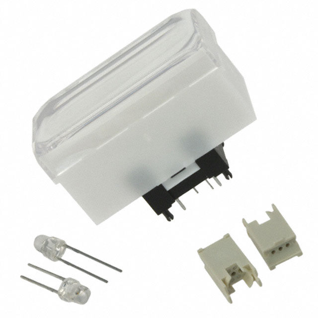
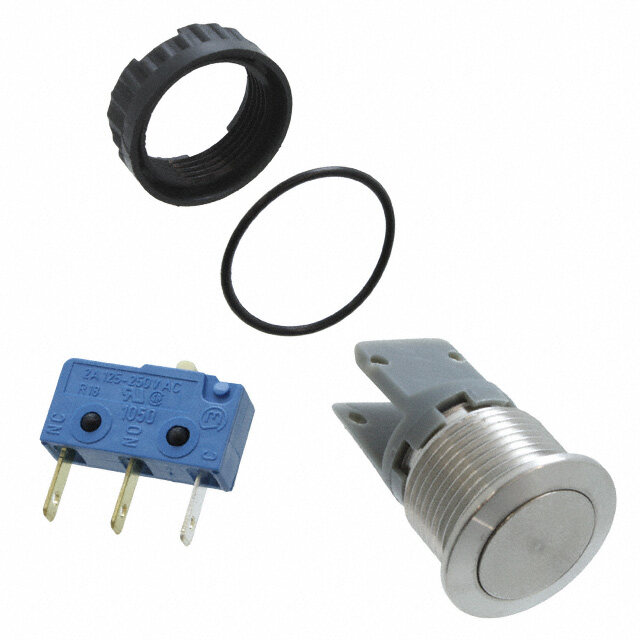
Series KP Miniature Audio/Video Pushbuttons s e RECTANGULAR CAP ASSEMBLY gl g o T CAP ASSEMBLY DIMENSIONS (3.6) (4.5) Switch/Rectangular Cap Assembly ers .142 .177 k c o R s n (34.8) (12.7) (7.62) L+1 butto 1.370 (2.54).500 .300 L– ush .100 1a P (0.6) (0.45)SqTyp .024 .018 B P d e D at n mi .(00.132) Illu (7.0) (12.7) e .276 .500 bl (17.4) (23.0) (6.0) (15.0)Sq ma .685 .906 .236 .591 m KP0115ACBKG03CJB for Tactile gra See below for complete assembly of switch, LEDs and LED holders. KP0115ANBKG03CJB for Nontactile o Pr LED SPECIFICATIONS s k c o yl e The electrical specifications shown are (+) (-) Color Red Unit K determined at a basic temperature of 25°C. Maximum Forward Current I 30 mA Center LED is an integral part of the switch. FM s e LLEEDDs c airrceu intso ta sroe ldis osleapteadra atenldy. r equire an TFyopriwcaalr dF oVrowltaargde Current IVF 22.00 mVA Rotari external power source. F Maximum Reverse Voltage V 4 V If the source voltage exceeds the rated RM voltage, a ballast resistor is required. Dominant Wavelength λ 623 nm es d d The resistor value can be calculated by us- Current Reduction Rate Above 25°C ∆I 0.32 mA/°C Sli ing the formula in the Supplement Section. F Ambient Temperature Range –25 ~ +50 °C Contact factory for other LED colors. s e ctil a ASSEMBLY & INSTALLATION INSTRUCTIONS T (3.1)Dia (2.54) (0.9) Dia Typ (4.5) .122 Cathode .100 .035 .177 LED (1.3) Dia Typ Tilt .051 (12.7) .500 Footprint L+ 1 (7.62) (12.7)(22.86) .300 .500 .900 (5.9) (2.1.0504) L– 1a ch .232 ou LED Holder T (6.7) .264 (0.8) Dia Typ (2.54) (4.8) (10.4) .031 .100 .189 .409 (.1520.70) ors LED LED Holder cat di 1 Install LED into LED Holder n I Switch/Rectangular Cap assembly has 3 LEDs (quantity 2). to achieve bright and even illumination. es 2 Solder LEDs and LED Holders ori s s into PCB. e One LED (in center of switch bottom) is an cc A integral part of the switch; the other 2 LEDs 3 Solder switch into PCB making and 2 LED Holders are packaged separately. sure that the two outer LEDs ent m and LED Holders clear the bot- e pl Switch PCB tom side opening of the cap. up S www.nkkswitches.com D45
Series KP Miniature Audio/Video Pushbuttons s e gl ASSEMBLY INSTRUCTIONS FOR SQUARE CAPS g o T Cap Orientation ATTENTION s er ELECTROSTATIC Notch k SENSITIVE DEVICES c Ro Tab Step As shown in the accompanying illustration, the cap and Plunger s plunger are designed with tabs and notches to assure proper Notches n utto orientation of the cap on the switch. b h s u P B P d e atD Removal of Cap Assembly & Separation of Lens & Diffuser n mi u Ill e bl Holding the switch tightly, pull the cap off the switch. Once the a m m cap assembly is released from the plunger, the lens and diffuser can a gr be separated. o Pr Pry up the lens with fingernail or flat tip screwdriver inserted at s the step on the diffuser. k c o yl e K Installation or Replacement of Cap Cap es Assembly ari ot R After aligning notches with tabs, join the lens and diffuser. Plunger Hold the switch tightly without touching the terminals. Firmly Switch press the cap onto the plunger by applying pressure from one es side to the other until both are snapped together. d Sli s e ctil a T Tilt h c u o T s or at c di n I s e ori s s e c c A nt e m e pl p u S D46 www.nkkswitches.com
Series KP Miniature Audio/Video Pushbuttons s e LEGENDS gl g o T NKK Switches can provide custom legends for caps. Contact factory for more information. s er k c o R Suggested Printable Areas for KP Lens Lens s n o utt b h Recommended Methods: us P Film LLaasseerr PErtcinht oonn ficllema rin lseenrst., Screen Print, or Pad Print on lens. Printing on Diffuser STOP DInisffeurster d PB e Epoxy based ink is recommended. is not advisable. D nat mi u Ill e bl a m m a gr Shaded areas are suggested printable areas for Lens. Rectangular Cap Lens o Pr s k c o yl e Flat Cap Lens Sculptured Cap Lens K (28.75) 1.132 (30.28) 1.192 es ari ot R (.93.886) Sq (.1520.84) Sq (.1532.48) Sq (.83.5937) Dia ( 0.0.7360) Typ ( 1.41.5428) Dia ( 0.0.7360) Typ ( 1.534.727) Dia ( 0.0.7360) Typ (1.35.4727) ( 0.0.7360) Typ es d ( 1.427.02) Sq ( 1.559.01) Sq (.1678.45) Sq ( 1.401.53) Dia ( 1.531.02) Dia (.1650.23) Dia (.1650.32) Sli s e Suggested Printable Areas for KP Film Insert ctil a T Shaded areas are suggested printable areas for Film Insert. Rectangular Film Insert (0.5) R Tilt .020 (2.125) Typ .084 Flat Cap Film Inserts Sculptured or Home Key Cap Film Inserts (28.75) ch 1.132 u o T (0.5) R (0.5) R (0.5) R (0.5) R (33.0) (0.5) R .020 .020 (0.5) R .020 .020 1.299 .020 .020 s or at c di n (8.28) Sq (0.76) Typ (11.28) Sq (0.76) Typ (11.88) Dia (0.76) Typ (8.28)Dia (0.76) Typ (11.28) Dia (0.76) Typ (11.88) Dia (0.76) Typ (13.77) (0.91) Typ I .326 .030 .444 .030 .468 .030 .326 .030 .444 .030 .468 .030 .542 .036 (9.8) Sq (12.8) Sq (13.4) Sq (9.8) Sq (12.8) Sq (13.4) Sq (15.6) s .386 .504 .528 .386 .504 .528 .614 orie s s e c c A Film Insert Material and Thickness: Clear Polyester; 4 mil (100µ) maximum thickness nt e m e pl p u S www.nkkswitches.com D47