ICGOO在线商城 > 分立半导体产品 > 晶闸管 - DIAC,SIDAC > K2200G

 Datasheet下载
- 型号: K2200G
- 制造商: Littelfuse
- 库位|库存: xxxx|xxxx
- 要求:
| 数量阶梯 | 香港交货 | 国内含税 |
| +xxxx | $xxxx | ¥xxxx |
查看当月历史价格
查看今年历史价格
K2200G产品简介:
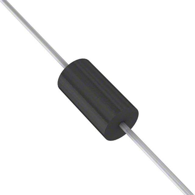
ICGOO电子元器件商城为您提供K2200G由Littelfuse设计生产,在icgoo商城现货销售,并且可以通过原厂、代理商等渠道进行代购。 K2200G价格参考。LittelfuseK2200G封装/规格:晶闸管 - DIAC,SIDAC, Diac/Sidac Thyristor 205 ~ 230V 1A DO-15。您可以下载K2200G参考资料、Datasheet数据手册功能说明书,资料中有K2200G 详细功能的应用电路图电压和使用方法及教程。
Littelfuse Inc.生产的K2200G是一款双向二极管晶闸管(DIAC),广泛应用于需要精确触发和开关功能的电路中。以下是该型号的一些典型应用场景:

1. 触发电路:K2200G常用于触发双向晶闸管(TRIAC)或可控硅(SCR)。通过其对称的导通特性,它可以提供稳定的触发电压,确保下游器件在预定条件下准确开启。

2. 灯泡调光器:在家庭或工业照明系统中,K2200G可用于调光器电路。它能够控制相位角,从而调节灯泡亮度,适用于白炽灯、卤素灯等传统光源的调光应用。

3. 电机速度控制:在小型电机的速度控制系统中,K2200G可以帮助实现平滑的速度调节。通过调整触发角度,可以改变电机的工作电压,进而控制其转速。

4. 家用电器控制:许多家用电器如风扇、电吹风等需要可变速度或功率输出的功能,K2200G可以作为核心元件之一来实现这些功能。

5. 电源管理:在某些电源管理应用中,K2200G可用于启动电路或者保护电路,确保设备在特定条件下正常工作并防止过载。

6. 信号处理与转换:在一些信号处理电路中,K2200G可以用作信号整形或转换元件,帮助生成特定波形或进行电平转换。

由于其高可靠性、稳定性和耐久性,K2200G非常适合各种需要精准控制和高效能表现的应用场合。同时,它的紧凑设计也使得它易于集成到不同的电子系统中。
| 参数 | 数值 |
| 产品目录 | |
| 描述 | SIDAC 205-230V 1A DO15硅对称二端开关元件 220V |
| 产品分类 | 二端交流开关元件,硅对称二端开关元件分离式半导体 |
| 品牌 | Littelfuse Inc |
| 产品手册 | |
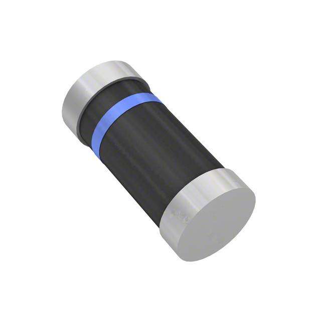
| 产品图片 |
|
| rohs | 符合RoHS无铅 / 符合限制有害物质指令(RoHS)规范要求 |
| 产品系列 | 晶体闸流管,硅对称二端开关元件,Littelfuse K2200G- |
| 数据手册 | |
| 产品型号 | K2200G |
| 不重复通态电流 | 16.7 A, 20 A |
| 产品种类 | 硅对称二端开关元件 |
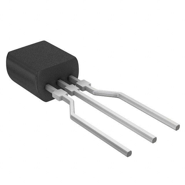
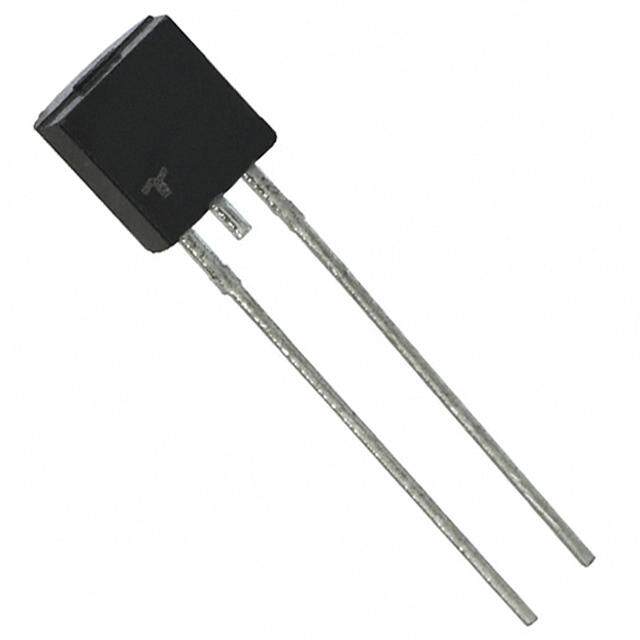
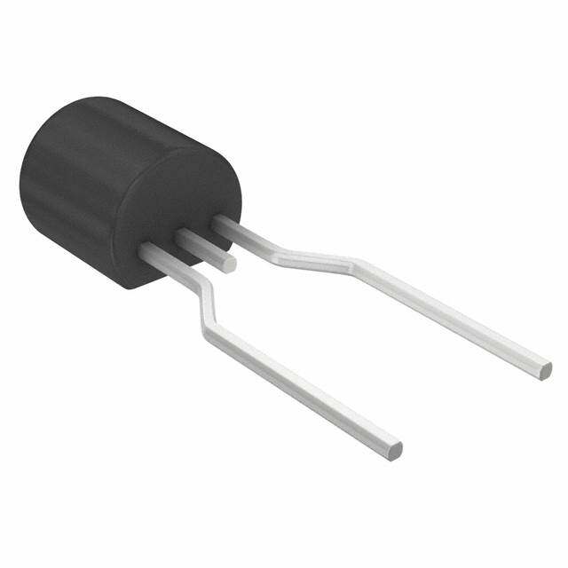
| 供应商器件封装 | DO-15 |
| 保持电流Ih最大值 | 150 mA |
| 关闭状态漏泄电流(在VDRMIDRM下) | 5 uA |
| 包装 | 散装 |
| 商标 | Littelfuse |
| 安装风格 | Through Hole |
| 封装 | Bulk |
| 封装/外壳 | DO-204AC,DO-15,轴向 |
| 封装/箱体 | DO-15X-2 |
| 工作结温 | - 40 C to + 125 C |
| 工厂包装数量 | 1000 |
| 开启状态RMS电流-ItRMS | 1 A |
| 开启状态电压 | 1.5 V |
| 最大工作温度 | + 85 C |
| 最大转折电流IBO | 10 uA |
| 最小工作温度 | - 40 C |
| 标准包装 | 1,000 |
| 电压-导通 | 205 ~ 230V |
| 电流-保持(Ih)(最大值) | 150mA |
| 电流-击穿 | 10µA |
| 电流-峰值输出 | 1A |
| 电流额定值 | 1 A |
| 系列 | Kxxxzy |
| 转折电流VBO | 205 V to 230 V |
| 额定重复关闭状态电压VDRM | +/- 180 V |


- 商务部:美国ITC正式对集成电路等产品启动337调查
- 曝三星4nm工艺存在良率问题 高通将骁龙8 Gen1或转产台积电
- 太阳诱电将投资9.5亿元在常州建新厂生产MLCC 预计2023年完工
- 英特尔发布欧洲新工厂建设计划 深化IDM 2.0 战略
- 台积电先进制程称霸业界 有大客户加持明年业绩稳了
- 达到5530亿美元!SIA预计今年全球半导体销售额将创下新高
- 英特尔拟将自动驾驶子公司Mobileye上市 估值或超500亿美元
- 三星加码芯片和SET,合并消费电子和移动部门,撤换高东真等 CEO
- 三星电子宣布重大人事变动 还合并消费电子和移动部门
- 海关总署:前11个月进口集成电路产品价值2.52万亿元 增长14.8%
PDF Datasheet 数据手册内容提取
Teccor® brand Thyristors Standard Bidirectional SIDACs Kxxxzy SIDAC RoHS Description The SIDAC is a silicon bilateral voltage triggered switch. Upon application of a voltage exceeding the SIDAC breakover voltage point, the SIDAC switches on through a negative resistance region to a low on-state voltage. Conduction continues until the current is interrupted or drops below the minimum holding current of the device. SIDACs feature glass-passivated junctions to ensure a rugged and dependable device capable of withstanding harsh environments. Features • AC Circuit Oriented • RoHS Compliant • Triggering Voltage of 79V Schematic Symbol to 330V Applications Suitable for high voltage power supplies, natural gas igniters, high-pressure Sodium lamps, and Xenon flash ignition. Electrical Specifications (T = 25°C, unless otherwise specified) J Symbol Parameters Test Conditions Min Max Unit K0900y 79 97 K1050y 95 113 K1100y 104 118 K1200y 110 125 K1300y 120 138 K1400y 130 146 V Breakover/Trigger Voltage K1500y 140 170 V BO K1800y 165 195 K200zy 190 215 K220zy 205 230 K240zy 220 250 K250zy 240 280 K300zy 270 330 K0900y 70 K1050y 90 K1100y 90 K1200y 90 K1300y 90 K1400y 90 V Repetitive Peak Off-state Voltage K1500y 90 V DRM K1800y 140 K200zy 180 K220zy 180 K240zy 190 K250zy 200 K300zy 200 Note: xxx = voltage, z = circuit function, y = package © 2016 Littelfuse, Inc. Specifications are subject to change without notice. Revised: 03/25/16
Teccor® brand Thyristors Standard Bidirectional SIDACs Electrical Specifications (T = 25°C, unless otherwise specified) J Symbol Parameters Test Conditions Min Max Unit I On-state RMS Current 50/60Hz, T < 125°C 1 A T(RMS) J V = V I Repetitive Peak Off-state Current DRM 5 μA DRM 50/60Hz Sine Wave Kxxx0y 1.5 V Peak On-state Voltage I = 1A V TM T Kxxx2y 3.0 R = 100Ω I Dynamic Holding Current L 150 mA H 50/60Hz Sine Wave (V – V) R Switching Resistance, R= __B_O____S_ 50/60Hz Sine Wave 100 Ω S S (I – I ) S BO I Breakover Current 50/60Hz Sine Wave 10 μA BO 60Hz 80 I Peak Repetitive Pulse Current (refer to figure 4) t = 10μs A TRM p 5Hz 160 Peak Non-repetitive Surge Current 60Hz 20 I Single Cycle A TSM (refer to figure 5) 50Hz 16.7 di/dt Critical Rate of Rise of On-state Current 150 A/μs dv/dt Critical Rate of Rise of Off-state Voltage 1500 V/μs T Storage Temperature Range -40 150 °C S T Junction Temperature Range -40 125 °C J DO-15 18 R Thermal Resistance, Junction to Lead °C/W θJL DO-214 (1) 30 R Thermal Resistance, Junction to Case TO-92 35 °C/W θJC DO-15 75 R Thermal Resistance, Junction to Ambient °C/W θJA TO-92 95 Notes: xxx = voltage, z = circuit function, y = package (1) Mounted on 1 cm2 copper foil surface; two-ounce copper foil Additional Information Datasheet Resources Samples © 2016 Littelfuse, Inc. Specifications are subject to change without notice. Revised: 03/25/16
Teccor® brand Thyristors Standard Bidirectional SIDACs Figure 2: On-state Current vs. On-state Figure 1: V-I Characteristics Voltage (Typical) +I 9 IT mps 8 TJ = 25°C A IISH RS Current (i) – T 567 KKKxxxxxxxxx000GES Kxxx2G -V IDRMIBO +V state 4 n- RS=(V(IBSO--IBVOS)) VT VDRMVSVBO antaneous O 123 st n 0 0.6 1.0 1.4 1.8 2.2 2.6 3.0 3.4 3.8 Instantaneous On-state Voltage (v) – Volts T -I Figure 3: Power Dissipation vs. On-state Current Figure 4: Repetitive Peak On-state Current (I ) TRM (Typical) vs. Pulse Width at Various Frequencies On-State Power Dissipation [P] - WattsD(AV)011111222.........024688024 CLCSOUOeeARN DBRD:aEU RsNCiecTTs SWIiOsItDANivVA eAEC NFo COrGi RrILncMEud:iu :t cS itniinv FueisgoKuixdrexa xl122G KKKxxxxxxxxx000GES ak On-State Current (I) - AmpsTRM101001000 di/5d tk LHi11zm2 ki0tH LHzizne 60 Hz 5 Hz ITM tO 1/f Average 000...246 etitive Pe p e 0.0 R 1 0.0 0.1 0.2 0.3 0.4 0.5 0.6 0.7 0.8 0.9 1.0 1.0 10.0 100.0 1000.0 RMS On-State Current [IT(RMS)] - Amps Pulse Base Width (tO) - us Figure 5: Peak Non-repetitive Surge Current (I ) Figure 6: Normalized V Change vs. Junction TSM BO vs. Number of Cycles Temperature 100 4% SUPPLY FREQUENCY: 60 Hz Sinusoidal LOAD: Resistive 2% e)mps RVaMluSe O aNt -SSpTeAcTifiEe CdU JRuRnEctNioTn: I TTe mRMpeSr aMtuarxeimum Rated 0% KKKx11xxxxxx200GEG urge (Non-repetitive Current (I) – ATSM 10 V Change -- %BO---642%%% KKK222xxxxxx000EGS K1xx0S Peak SOn-stat N1acu)no rBdtre eliosmnc:tkm iinnetgde ircavataeplla.yb fioliltlyo wmianyg bseu rlogest during -8% 2) Overload may not be repeated until -10% junction temperature has returned to steady-state rated value. -12% 11 10 100 1000 -40 -20 0 20 40 60 80 100 120 140 Junction Temperature (T) -- °C Surge Current Duration -- Full Cycles J © 2016 Littelfuse, Inc. Specifications are subject to change without notice. Revised: 03/25/16
Teccor® brand Thyristors Standard Bidirectional SIDACs Figure 7: Normalized DC Holding Current Figure 8: Maximum Allowable Case Temperature vs. Junction Temperature vs. RMS On-State Current 2.0 e 130 ur at er mp 120 o of I / I(T = 25°C)HH J11..05 wable Lead/Case Te(T) - °CC111000 KKKxxxxxxxxx002SEG Kxxx0G Rati 0.5 Allo m 90 u m xi CURRENT WAVEFORM: Sinusoidal - 60Hz 0.0-40 -15 10 35 60 85 110 125 Ma 80 LOAD: Resistive or Inductive 0.0 0.2 0.4 0.6 0.8 1.0 1.2 Junction Temperature (T) -- °C RMS On-State Current [I ] - Amps J T(RMS) Figure 9: Maximum Allowable Ambient Temperature vs. Figure 10: Normalized Repetitive Peak Breakover RMS On-State Current Current (I ) vs. Junction Temperature BO 140 10 e ur CURRENT WAVEFORM: Sinusoidal - 60Hz Allowable Ambient Temperat(T) - °CA 1102680000 KKxxxxxx00SE LFOREAED A: KRIRxe sxRixsA0tTiGvINe Gor Inductive Repetitive Peak BreakoverCurrent (I) MultiplierBO m u m 40 Kxxx2G xi a M 25 20 1 0.0 0.2 0.4 0.6 0.8 1.0 20 30 40 50 60 70 80 90 100 110 120 130 RMS On-State Current [I ] - Amps Junction Temperature (T) -- °C T(RMS) J Figure 11: Dynamic Holding Current Test Circuit for Figure 12: Basic SIDAC Circuit SIDACs Push to test Switch to test S1 in each direction 100-250 V ac 60 Hz Device 1010% Ω UTensdter VBO VBO VBO 100-250 Vac S1 60 Hz IH Load IPK Scope 120-145˚ IIHH Trace Stops Conduction Angle Load Current IH Scope Indication © 2016 Littelfuse, Inc. Specifications are subject to change without notice. Revised: 03/25/16
Teccor® brand Thyristors Standard Bidirectional SIDACs Figure 13: Relaxation Oscillator Using a SIDAC Figure 14: Low-voltage Input Circuit for Gas Ignition 4.7 µF (a) Circuit - + 10 µF 100 V 4.7 k VBO (b) Waveforms - + R 50 V ½ W K1200E SIDAC VC + Sidac VDC(IN) ≥ VB0 VC - 41.070 µ VF 1.2 µF 200 V t C IL RL IL 2640 V H azc Rmax ≤ VINI B- OVBO t Rmin ≥ VIIHN (-M VITNM) H.V. Ignitor Figure 15: Comparison of SIDAC versus SCR for Gas Figure 16: Xenon Lamp Flashing Circuit Ignitor Circuit SCR Sidac 100 -10 µ+F Xenon Lamp 2 W 250 V 20 M K2200G + 100-250 V ac 100-250 V ac 10 µF 4 kV 60 Hz 60 Hz -450 V 120 V ac Sidac 0.01 µF 60 Hz 400 V 200- 400 V Trigger Transformer 20:1 Figure 17: Typical High-pressure Sodium Lamp Firing Circuit Ballast Ballast Sidac 0.47 µF Sidac 0.22 µF 400 V 3.3 k Lamp 7.5 k Lamp 120 V ac 220 V ac 60 Hz 60 Hz 16 mH 120 V ac 220 V ac © 2016 Littelfuse, Inc. Specifications are subject to change without notice. Revised: 03/25/16
Teccor® brand Thyristors Standard Bidirectional SIDACs Soldering Parameters Reflow Condition Pb – Free assembly t P T P - Temperature Min (Ts(min)) 150°C e RRaammpp--uupp Pre Heat -- TTeimmep e(mraitnu rteo Mmaaxx )( T(ts()max)) 2600 0–° C180 secs rutare TS(mTaxL) tL s p m RRaammpp--ddoown Average ramp up rate (Liquidus Temp) PPrreehheeaatt (TL) to peak 5°C/second max eT TS(min) t T to T - Ramp-up Rate 5°C/second max S S(max) L - Temperature (T) (Liquidus) 217°C Reflow L 25 - Temperature (tL) 60 – 150 seconds time to peak temperature Time Peak Temperature (T) 260+0/-5 °C P Time within 5°C of actual peak 20 – 40 seconds Temperature (t) p Ramp-down Rate 5°C/second max Time 25°C to peak Temperature (T) 8 minutes Max. P Do not exceed 280°C Physical Specifications Reliability/Environmental Tests Test Specifications and Conditions 100% Matte Tin Plated / Pb-free Solder Terminal Finish Dipped MIL-STD-750: Method 1040, Condition High Temperature A Rated V (VAC-peak), 125°C, 1008 Body Material UL recognized epoxy meeting flammability Voltage Blocking hours DRM classification 94V-0 MIL-STD-750: Method 1051 Temperature Cycling -40°C to 150°C, 15-minute dwell, 100 Lead Material Copper Alloy cycles EIA/JEDEC: JESD22-A101 Biased Temperature & 80% min V (V ), 85°C, 85%RH, 1008 Humidity BO DC Design Considerations hours Careful selection of the correct device for the application’s High Temp Storage MIL-STD-750: Method 1031 150°C, 1008 hours operating parameters and environment will go a long way toward extending the operating life of the Thyristor. Low-Temp Storage -40°C, 1008 hours Overheating and surge currents are the main killers of MIL-STD-750: Method 1056 SIDACs. Correct mounting, soldering, and forming of the Thermal Shock 0°C to 100°C, 5-minute dwell, leads also help protect against component damage. 10-second transfer, 10 cycles Autoclave EIA/JEDEC: JESD22-A102 (Pressure Cooker Test) 121°C, 100%RH, 2atm, 168 hours Resistance to MIL-STD-750: Method 2031 Solder Heat 260°C, 10 seconds Solderability ANSI/J-STD-002: Category 3 Lead Bend MIL-STD-750: Method 2036, Condition E © 2016 Littelfuse, Inc. Specifications are subject to change without notice. Revised: 03/25/16
Teccor® brand Thyristors Standard Bidirectional SIDACs Dimensions — DO-214 Case Temperature Inches Millimeters Measurement Dimension B Point Max Max Min Max D A 0.130 0.156 3.30 3.95 C A B 0.201 0.220 5.10 5.60 C 0.077 0.087 1.95 2.20 D 0.159 0.181 4.05 4.60 E 0.030 0.063 0.75 1.60 H F F 0.075 0.096 1.90 2.45 E K G G 0.002 0.008 0.05 0.20 0.079 (2.0) H 0.077 0.104 1.95 2.65 K 0.006 0.016 0.15 0.41 inch 0.110 (2.8) (millimeter) 0.079 (2.0) Recommended Soldering Pad Outline Dimensions — DO-15 Temperature Measuring Point Inches Millimeters ØD Dimension Max Max Min Max ØB ØB 0.028 0.034 0.711 0.864 ØD 0.120 0.140 3.048 3.556 L G L G 0.235 0.270 5.969 6.858 L 1.000 25.400 © 2016 Littelfuse, Inc. Specifications are subject to change without notice. Revised: 03/25/16
Teccor® brand Thyristors Standard Bidirectional SIDACs Dimensions — TO-92 with Type 70 Lead Form Temperature Measuring Point Inches Millimeters Dimension Max Max Min Max A A 0.176 0.196 4.47 4.98 B 0.500 12.70 N D 0.095 0.105 2.41 2.67 E 0.150 3.81 F 0.046 0.054 1.16 1.37 G 0.135 0.145 3.43 3.68 B H 0.088 0.096 2.23 2.44 J 0.176 0.186 4.47 4.73 K 0.088 0.096 2.23 2.44 L 0.013 0.019 0.33 0.48 M 0.013 0.017 0.33 0.43 MT1 MT2 N 0.060 1.52 Notes: E 1. Type 70 lead form as shown is standard for the E package. 2. All leads are insulated from case. Case is electrically nonconductive (rated at 16000V ac G rms for one minute from leads to case over the operating temperature range.) M H 3. Mold flash shall not exceed 0.13 mm per side. F L D K J Product Selector Switching Voltage Range Blocking Voltage Packages Part Number V Minimum V Maximum V DO-15 DO-214 TO-92 BO BO DRM K0900y 79V 97V 70V K0900G K0900S K0900E70 K1050y 95V 113V 90V K1050G K1050S K1050E70 K1100y 104V 118V 90V K1100G K1100S K1100E70 K1200y 110V 125V 90V K1200G K1200S K1200E70 K1300y 120V 138V 90V K1300G K1300S K1300E70 K1400y 130V 146V 90V K1400G K1400S K1400E70 K1500y 140V 170V 90V K1500G K1500S K1500E70 K1800y 165V 195V 140V K1800S K2000y 190V 215V 180V K2000G K2000S K2000E70 K2002y 190V 215V 180V K2002G K2200y 205V 230V 180V K2200G K2200S K2200E70 K2202y 205V 230V 180V K2202G K2400y 220V 250V 190V K2400G K2400S K2400E70 K2402y 220V 250V 190V K2402G K2500y 240V 280V 200V K2500G K2500S K2500E70 K2502y 240V 280V 200V K2502G K3002y 270V 330V 200V K3002G Note: y = package © 2016 Littelfuse, Inc. Specifications are subject to change without notice. Revised: 03/25/16
Teccor® brand Thyristors Standard Bidirectional SIDACs Packing Options Part Number Marking Weight Packaging Mode Base Quantity Kxxx0G Kxxx0G 0.38g Bulk 1000 Kxxx0GRP Kxxx0G 0.38g Reel Pack 5000 Kxxx2G Kxxx2G 0.38g Bulk 1000 Kxxx2GRP Kxxx2G 0.38g Reel Pack 5000 Kxxx0SRP KxxS 0.1g Reel Pack 2500 Kxxx0E70 Kxxx0E 0.17g Bulk 2000 Kxxx0E70AP Kxxx0E 0.17g Ammo Pack 2000 Kxxx0E70RP2 Kxxx0E 0.17g Reel Pack 2000 Kxxx0E70RP3 Kxxx0E 0.17g Reel Pack 2000 Note: xxx or xx = voltage DO-214 Embossed Carrier Reel Pack (RP) Specifications 0.157 (4.0) 0.472 (12.0) 0.36 (9.2) 0.315 (8.0) 0.059 (1.5) DIA Cover tape 12.99 0.512 (13.0) Arbor (330.0) Hole Dia. Dimensions are in inches (and millimeters). 0.49 (12.4) Direction of Feed © 2016 Littelfuse, Inc. Specifications are subject to change without notice. Revised: 03/25/16
Teccor® brand Thyristors Standard Bidirectional SIDACs DO-15 Reel Pack (RP) Specifications DO-15 2.063 (52.4) 0.898 (22.8) 0.252 (6.4) 0.197 10.0 - 14.0 (5.0) (254.0 - 356.0) Dimensions are in inches (and millimeters). 3.15 (80.0) TYP Direction of Feed DO-15 Ammo Pack (AP) Specifications Direction of Feed DO-15 2.063 (52.4) 4.53 (115.0) 0.898 (22.8) 0.252 (6.4) Dimensions 0.197 are in inches (5.0) (and millimeters). 3.27 (80.0) 9.8 (250.0) © 2016 Littelfuse, Inc. Specifications are subject to change without notice. Revised: 03/25/16
Teccor® brand Thyristors Standard Bidirectional SIDACs TO-92 Type 70 Reel Pack (RP3) Radial Leaded Specifications 0.236 0.02 (0.5) (6.0) 0.91 1.3 (23.2) (33.0) 0.708 (18.0) 0.354 (9.0) 0.5 0.1 (2.54) (12.7) 0.157 DIA (4.0) 14.17 (360.0) Dimensions are in inches (and millimeters). Flat Up 1.97 (50.0) Direction of Feed TO-92 Type 70 Reel Pack (RP2) Radial Leaded Specifications 0.25 0.50 (6.35) (12.7) 0.236 0.02 (6.0) (0.5) 0.125 (3.2) MAX 0.91 1.30 (23.2) (33.0) 0.708 (18.0) 0.354 (9.0) 0.50 0.20 (12.7) (5.08) 0.157DIA (4.0) 14.17 (360.0) Flat Down Dimensions 1.97 are in inches (50.0) (and millimeters). Direction of Feed © 2016 Littelfuse, Inc. Specifications are subject to change without notice. Revised: 03/25/16
Teccor® brand Thyristors Standard Bidirectional SIDACs TO-92 Type 70 Ammo Pack (AP) Radial Leaded Specifications 0.50 0.25 (12.7) (6.35) 0.236 0.02 (0.5) 1.30 (6.0) 0.125 (3.2) MAX 0.91 (33.0) (23.2) MAX 0.708 (18.0) 0.354 (9.0) (01.25.07) 0.20 (5.08) 0(4.1.05)7DIA Flat down Directionof Feed 25 Devices per fold 1.85 (47.0) 12.2 (310.0) Dimensions are in inches 1.85 (and millimeters). (47.0) 13.3 (338.0) Part Numbering System Part Marking System TO-92 K 240 0 E 70 RP2 DO-214AA K2400E DEVICE TYPE PACKAGING OPTIONS K24S K: Sidac [blank]: Bulk AP: Ammo(TO-92) VOLTAGE RATING RRPP2:: RReeeell((nToOn-9 T2O)-92) ® YMLXX YMXXX 090: 79 –97V RP3: Reel(TO-92) 105: 95 –113V 110: 104 –118V LEAD FORM DIMENSIONS Date Code Marking 120: 110 –125V xx: Lead Form Option Y:Year Code 130: 120 –138V M: Month Code 140: 130 –146V Date Code Marking XXX: Lot Trace Code 150: 140 –170V PACKAGE TYPE Y:Year Code 180: 165 –195V G: DO-15 M: Month Code 200: 190 –215V S: DO-214 L: Location Code 220: 205 –230V E: TO-92 240: 220 –250V XX: Lot Serial Code 235000:: 224700 ––238300VV C0:I R SCtUanITd aFrUdNCTION DO-15 2: Two Series Die K2400G YMXXX ® © 2016 Littelfuse, Inc. Specifications are subject to change without notice. Revised: 03/25/16