 Datasheet下载
- 型号: JSM1-12V-5
- 制造商: Panasonic Corporation
- 库位|库存: xxxx|xxxx
- 要求:
| 数量阶梯 | 香港交货 | 国内含税 |
| +xxxx | $xxxx | ¥xxxx |
查看当月历史价格
查看今年历史价格
JSM1-12V-5产品简介:
ICGOO电子元器件商城为您提供JSM1-12V-5由Panasonic Corporation设计生产,在icgoo商城现货销售,并且可以通过原厂、代理商等渠道进行代购。 JSM1-12V-5价格参考。Panasonic CorporationJSM1-12V-5封装/规格:汽车继电器, 。您可以下载JSM1-12V-5参考资料、Datasheet数据手册功能说明书,资料中有JSM1-12V-5 详细功能的应用电路图电压和使用方法及教程。
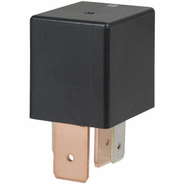
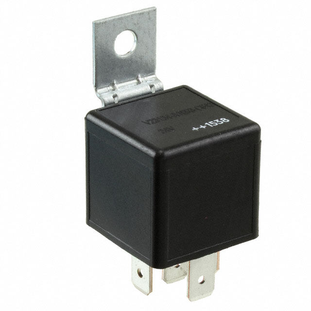
Panasonic Electric Works(现为Panasonic Industrial Devices)生产的JSM1-12V-5汽车继电器是一种小型密封继电器,广泛应用于汽车电子控制系统中。以下是该型号继电器的主要应用场景:

 1. 汽车电气系统控制
   - 车灯控制:用于控制前大灯、尾灯、转向灯等照明系统的开关。
   - 电动窗和天窗控制:通过继电器实现电动窗的升降和天窗的开闭功能。
   - 雨刷系统:控制雨刷电机的启动、停止和速度调节。

 2. 发动机管理系统
   - 燃油泵控制:在发动机启动时,继电器负责接通燃油泵电路,确保燃油供应。
   - 冷却风扇控制:根据发动机温度传感器信号,控制冷却风扇的启停。
   - 启动马达控制:辅助启动马达电路的接通与断开。

 3. 舒适性与便利性功能
   - 空调系统:控制空调压缩机的运行状态,调节车内温度。
   - 座椅加热/通风:用于座椅加热或通风功能的电源切换。
   - 音响系统:保护音频功放电路,避免电流过大损坏设备。

 4. 安全系统
   - 气囊系统:在某些情况下,继电器用于控制气囊模块的供电。
   - 防盗报警系统:实现报警器的触发和关闭。
   - 倒车雷达和摄像头:控制倒车雷达和摄像头的电源开关。

 5. 其他应用
   - 电动车窗防夹功能:通过继电器配合传感器实现防夹保护。
   - 中央门锁系统:控制车门锁的开启和关闭。
   - 后备箱开启:用于遥控或手动开启后备箱的功能。

 特点与优势
- 额定电压12V:适用于大多数汽车的电气系统。
- 小型化设计:节省空间,便于安装在狭小的汽车内部环境。
- 高可靠性:密封结构防止灰尘和水分侵入,适合恶劣的车载环境。
- 长寿命:能够承受频繁的开关操作,满足汽车长期使用需求。

总之,JSM1-12V-5继电器凭借其稳定性和适应性,在现代汽车的各种电气和电子控制系统中扮演着重要角色。
| 参数 | 数值 |
| 产品目录 | |
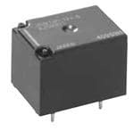
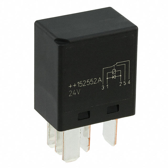
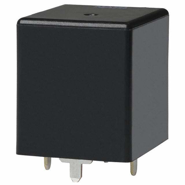
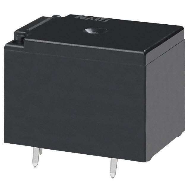
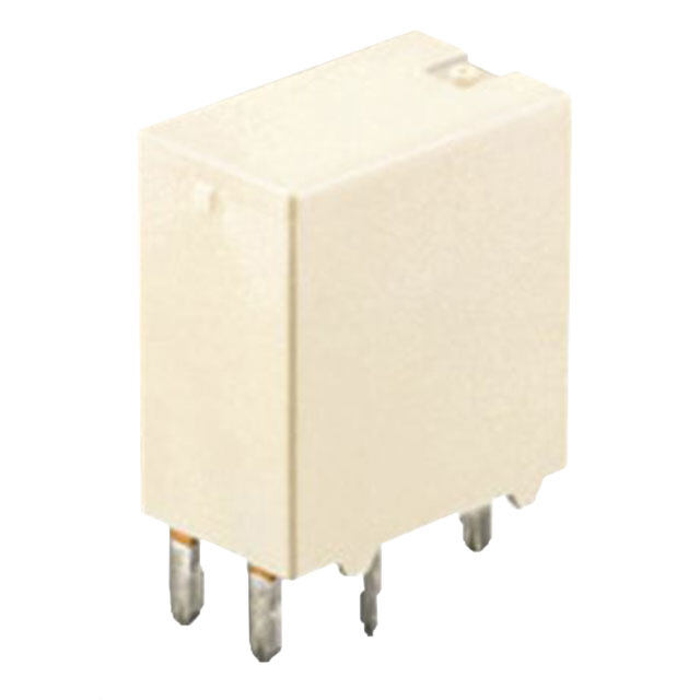
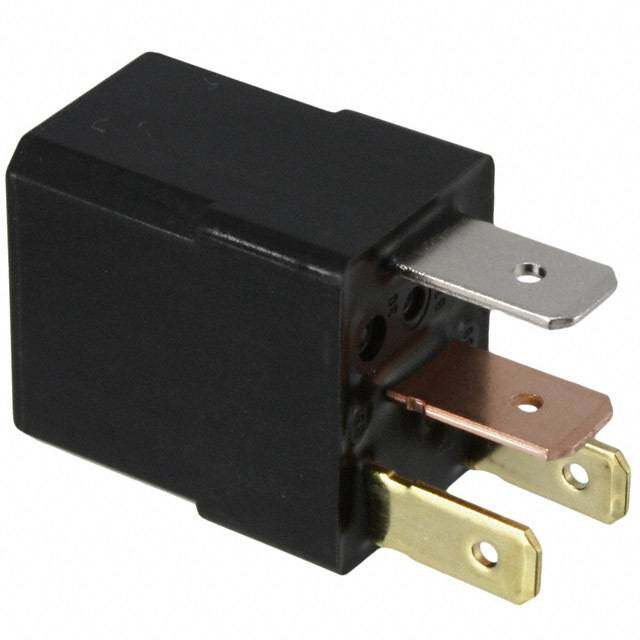
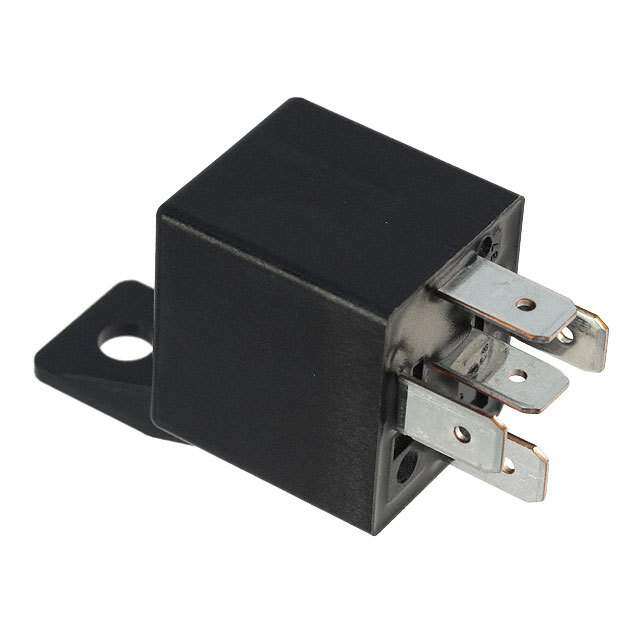
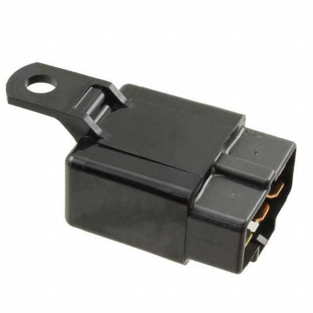
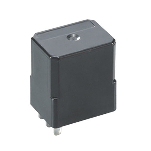
| 描述 | RELAY AUTOMOTIVE SPDT 15A 12V车用继电器 15A 12VDC SPDT HI-CAP SEALED PCB |
| 产品分类 | |
| 品牌 | Panasonic Electric Works |
| 产品手册 | |
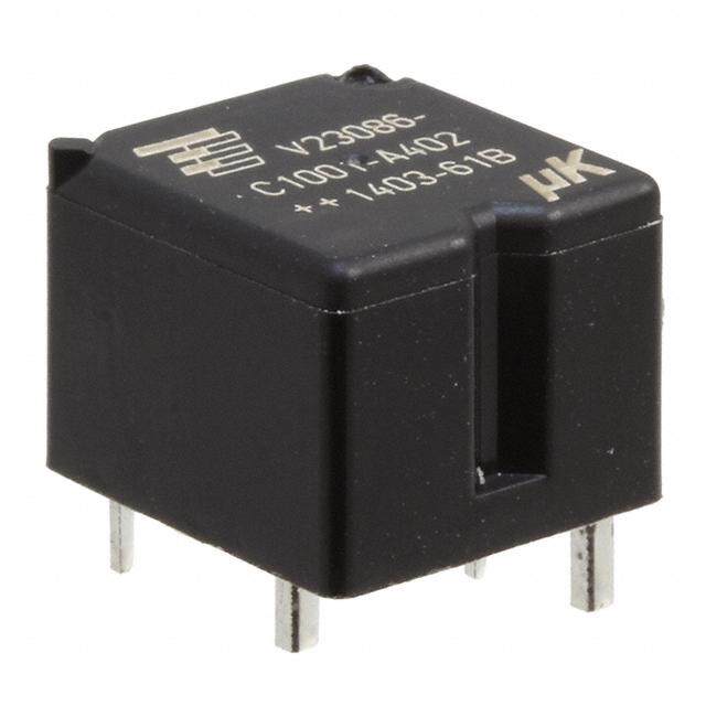
| 产品图片 |
|
| rohs | RoHS 合规性豁免无铅 / 符合限制有害物质指令(RoHS)规范要求 |
| 产品系列 | 车用继电器,Panasonic Industrial Devices JSM1-12V-5JS-M |
| mouser_ship_limit | 该产品可能需要其他文件才能进口到中国。 |
| 数据手册 | |
| 产品型号 | JSM1-12V-5 |
| 产品目录绘图 |
|
| 产品目录页面 | |
| 产品种类 | 车用继电器 |
| 关闭电压(最小值) | 0.9 VDC |
| 其它名称 | 255-1240 |
| 其它有关文件 | |
| 功耗 | 640 mW |
| 包装 | 散装 |
| 商标 | Panasonic Industrial Devices |
| 安装类型 | 通孔 |
| 安装风格 | Through Hole |
| 导通电压(最大值) | 6.3 VDC |
| 封装 | Bulk |
| 工作时间 | 10ms |
| 工作温度 | -40°C ~ 85°C |
| 工厂包装数量 | 100 |
| 开关电压 | 16VDC - 最小值 |
| 标准包装 | 100 |
| 特性 | 密封式 - 全部 |
| 端子类型 | PC 引脚 |
| 类型 | Automotive Relays |
| 线圈功率 | 640 mW |
| 线圈电压 | 12VDC |
| 线圈电流 | 53.3mA |
| 线圈电阻 | 225 欧姆 |
| 线圈端接 | Solder Terminal |
| 线圈类型 | 无锁存 |
| 继电器类型 | 自动 |
| 触头外形 | SPDT(1 C 型) |
| 触头材料 | 银合金,无镉 |
| 触点形式 | 1 Form C (SPDT-BM) |
| 触点材料 | Silver Alloy |
| 触点电流额定值 | 15 A |
| 触点端接 | Solder Terminal |
| 释放时间 | 10ms |
| 额定接触(电流) | 15A |


- 商务部:美国ITC正式对集成电路等产品启动337调查
- 曝三星4nm工艺存在良率问题 高通将骁龙8 Gen1或转产台积电
- 太阳诱电将投资9.5亿元在常州建新厂生产MLCC 预计2023年完工
- 英特尔发布欧洲新工厂建设计划 深化IDM 2.0 战略
- 台积电先进制程称霸业界 有大客户加持明年业绩稳了
- 达到5530亿美元!SIA预计今年全球半导体销售额将创下新高
- 英特尔拟将自动驾驶子公司Mobileye上市 估值或超500亿美元
- 三星加码芯片和SET,合并消费电子和移动部门,撤换高东真等 CEO
- 三星电子宣布重大人事变动 还合并消费电子和移动部门
- 海关总署:前11个月进口集成电路产品价值2.52万亿元 增长14.8%

PDF Datasheet 数据手册内容提取
JS-M GLOBAL STANDARD TERMINAL PITCH JS-M RELAYS AUTOMOTIVE POWER RELAY FEATURES TYPICAL APPLICATIONS • Low pick-up voltage for high ambient • Power-window use • Car antenna • Sealed construction • Door lock • Global standard terminal pitch • Intermittent wiper • Usable at high temperature: 85°C • Interior lighting 185°F • Power seat • Power sunroof • Car stereo • Horn • Lift gate, etc. RoHS compliant ORDERING INFORMATION JSM 12V Contact arrangement 1a:1 Form A 1: 1 Form C Protective construction Nil: Sealed type F: Flux-resistant type Coil voltage (DC) 12 V Contact capacity 4: Standard type 5: High capacity type TYPES Standard type High capacity type Contact arrangement Coil voltage Sealed type Flux-resistant type Sealed type Flux-resistant type Part No. Part No. Part No. Part No. 1 Form A 12 V DC JSM1a-12V-4 JSM1aF-12V-4 JSM1a-12V-5 JSM1aF-12V-5 1 Form C 12 V DC JSM1-12V-4 JSM1F-12V-4 JSM1-12V-5 JSM1F-12V-5 Standard packing; Carton: 100 pcs.; Case: 500 pcs. RATING 1. Coil data Pick-up voltage Drop-out voltage Nominal operating Novmoilntaagl ecoil (at 2(0In°iCtia 6l)8°F) (at 2(0In°iCtia 6l)8°F) [±10%] c(autr r2e0n°tC 68°F) [±10C%o]i l (raets 2is0t°aCn c6e8 °F) Nominpaol wopeerrating Usable voltage range 12V DC Max. 6.3 V DC Min. 0.9 V DC 53.3 mA 225Ω 640 mW 10 to 16V DC Note:Other pick-up voltage types are also available. Please contact us for details. ASCTB236E 201201-T Panasonic Corporation Automation Controls Business Unit industrial.panasonic.com/ac/e
JS-M 2. Specifications Specifications Characteristics Item Standard type High capacity type Arrangement 1 Form A 1 Form C 1 Form A 1 Form C Max. 200 mΩ Max. 100 mΩ Contact resistance (Initial) Contact (Measured after operating 5 times, 6V DC 1A) (By voltage drop 6V DC 1A) Contact voltage drop Max. 0.2 V DC (at 10 A 12 VDC) Contact material Ag alloy (Cadmium free) Nominal switching capacity (resistive load) 10A 16V DC 15A 16V DC 25 A (at 20°C 68°F for 2 minutes), 15 A (at 20°C 68°F for 1 hour), Max. carrying current*3 20 A (at 85°C 185°F for 2 minutes), 10 A (at 85°C 185°F for 1 hour) Max. switching power (resistive load) 160 mW 240 W Rating Max. switching voltage 16V DC Max. switching current 10 A 15 A (Max. 10 A at 85°C 185°F) Nominal operating power 640 mW Min. switching capacity (resistive load)*1 1 A 12 V DC Insulation resistance (Initial) Min. 100 MΩ (at 500V DC) Breakdown voltage Between open contacts 750 Vrms for 1 min. (Detection current: 10mA) Electrical (Initial) Between contacts and coil 1,500 Vrms for 1 min. (Detection current: 10mA) characteristics Operate time (at 20°C 68°F) Max. 10ms (at nominal voltage) (excluding contact bounce time) Release time (at 20°C 68°F) Max. 10ms (at nominal voltage) (excluding contact bounce time, without diode) Functional Min. 98 m/s2 {10G} (Half-wave pulse of sine wave: 11ms; detection time: 10µs) Shock resistance Mechanical Destructive Min. 980 m/s2 {100G} (Half-wave pulse of sine wave: 6ms) characteristics Functional 10 Hz to 55 Hz, at double amplitude of 1.6 mm (Detection time: 10µs) Vibration resistance Destructive 10 Hz to 55 Hz, at double amplitude of 2.0 mm N.O.: Min. 105 (at 15 cpm), Expected life Electrical (at nominal switching capacity) Min. 105 (at 15 cpm) N.C.: Min. 5 × 10⁴ (at 15 cpm) Mechanical Min. 107 (at 180 cpm) Ambient temperature: –40°C to +85°C –40°F to +185°F, Conditions for operation, transport and storage*2 Conditions Humidity: 5% R.H. to 85% R.H. (Not freezing and condensing at low temperature) Max. operating speed 15 cps. (at nominal switching capacity) Notes:*1.This value can change due to the switching frequency, environmental conditions, and desired reliability level, therefore it is recommended to check this with the actual load. *2.The upper operation ambient temperature limit is the maximum temperature that can satisfy the coil temperature rise value. Please refer to “Usage ambient condition” in CAUTIONS FOR USE OF AUTOMOTIVE RELAYS. *3.Depends on connection conditions. Also, this does not guarantee repeated switching. We recommend that you confirm operation under actual conditions. REFERENCE DATA 1-(1). Coil temperature rise (10A) 1-(2). Coil temperature rise (15A) 2. Max. switching capability Measured portion: Inside the coil Measured portion: Inside the coil (Resistive load, initial) Contact carrying current, 10A Contact carrying current, 15A Ambient temperature: Room temperature, 85°C Ambient temperature: Room temperature, 85°C 185°F 185°F (N.O. side: room temperature) 120 120 60 °Temperature rise, C1086000 Rt8e5om°oCpme rature °Temperature rise, C1086000 8Rte5om°oCpme rature witching voltage, VDC 543000 40 40 S 20 20 20 10 0 0 0 12 14 16 12 14 16 0 10 20 30 40 50 Coil applied voltage, V Coil applied voltage, V Switching current, A ASCTB236E 201201-T Panasonic Corporation Automation Controls Business Unit industrial.panasonic.com/ac/e
JS-M 3. Ambient temperature and oprating voltage 4. Distribution of pick-up and drop-out voltage 5. Distribution of operate and release time range Sample: JSM1-12V-5, 50pcs. Sample: JSM1-12V-5, 50pcs. Coil both side without diode 40 70 50 Pick-up voltage Operate time DC 35 60 Drop-out voltage Release time V 40 plied voltage, 322050 Quantity, n 4500 Quantity, n 30 p 30 oil a 15 20 C 20 10 10 5 10 Pick-up voltage (cold start) 0 0 0 −40−20 0 20 40 60 8085100120 0 0.5 1 1.5 2 2.5 3 3.5 4 4.55 5.5 6 1 1.5 2 2.5 3 3.5 4 4.5 Ambient temperature, °C Voltage, V Time, ms 6-(1). Electrical life test (Motor load) Sample: JSM1-12V-5, 3pcs. Load: 50A (Inrush), 10A 16V DC (Steady) Switching frequency: (ON : OFF = 1s : 9s) 6 V Contact welding: 0 times e, Miscontact: 0 times g 5 a Circuit : out volt 4 Pick-up voltage XMax. p- Min. Tested sample d dro 3 n a 16V DC M Pick-up 2 Drop-out voltage XMMainx.. 12V DC 1 0 0 5 10 No. of operations, × 104 6-(2). Electrical life test (Lamp load) Sample: JSM1a-12V-5, 4pcs. Load: 55.2A (Inrush), 9.6A 14.5V DC (Steady) Switching frequency: (ON : OFF = 1s : 3s) 6 V Pick-up voltage Max. e, X ag 5 Min. olt Contact welding: 0 times Circuit : ut v 4 Miscontact: 0 times o p- Tested sample d dro 3 p an Drop-out voltage Max. u 2 X 14.5V DC Pick- Min. 12V DC 1 0 0 5 10 15 No. of operations, × 104 ASCTB236E 201201-T Panasonic Corporation Automation Controls Business Unit industrial.panasonic.com/ac/e
JS-M DIMENSIONS (mm inch) The CAD data of the products with a CAD Data mark can be downloaded from: http://industrial.panasonic.com/ac/e CAD Data External dimensions Schematic (Bottom view) 1a N.O. .61360 COIL COM 0.4 .016 3.9 A* .154 1c 0.24 .009 N.O. 0.8 0.8 .031 .031 COM COIL 0.4 .016 N.C. 1.2 .047 2 3N.O. 1 .41722.61360 PC board pattern (Bottom view) 5 4N.C. 1a 2.3 0.4 4-1.3 dia. .091 .016 4-.051 dia. 2 12.2 .079 .480 22 .866 12 .472 Dimension: General tolerance Max. 1mm .039 inch: ±0.1 ±.004 2 12.2 1 to 3mm .039 to .118 inch: ±0.2 ±.008 .079 .480 Min. 3mm .118 inch: ±0.3 ±.012 1c 5-1.3 dia. *Dimensions (thickness and width) of terminal specified in this catalog is measured before pre-soldering. 5-.051 dia. Intervals between terminals is measured at A surface level. 12 .472 2 12.2 .079 .480 Tolerance: ±0.1 ±.004 For Cautions for Use, see Relay Technical Information. ASCTB236E 201201-T Panasonic Corporation Automation Controls Business Unit industrial.panasonic.com/ac/e
Mouser Electronics Authorized Distributor Click to View Pricing, Inventory, Delivery & Lifecycle Information: P anasonic: JSM1-12V-4 JSM1-12V-5 JSM1a-12V-5 JSM1aF-12V-5 JSM1-9V-4 JSM1-9V-5 JSM1A-9V-4 JSM1A-9V-5 JSM1A-12V-4