 Datasheet下载
- 型号: JB15HBPF-BH
- 制造商: NKK Switches
- 库位|库存: xxxx|xxxx
- 要求:
| 数量阶梯 | 香港交货 | 国内含税 |
| +xxxx | $xxxx | ¥xxxx |
查看当月历史价格
查看今年历史价格
JB15HBPF-BH产品简介:
ICGOO电子元器件商城为您提供JB15HBPF-BH由NKK Switches设计生产,在icgoo商城现货销售,并且可以通过原厂、代理商等渠道进行代购。 JB15HBPF-BH价格参考。NKK SwitchesJB15HBPF-BH封装/规格:触摸开关, 顶部触动 触摸开关 SPST-NO 通孔。您可以下载JB15HBPF-BH参考资料、Datasheet数据手册功能说明书,资料中有JB15HBPF-BH 详细功能的应用电路图电压和使用方法及教程。
NKK Switches的JB15HBPF-BH是一款触摸开关,属于高精度、高可靠性的电子开关元件。该型号具备良好的灵敏度和稳定性,适用于多种电子设备和控制系统中。

其主要应用场景包括:

1. 消费电子产品:如智能手机、平板电脑、智能手表等设备中的触摸控制面板,用于实现触控操作功能。

2. 家用电器:应用于微波炉、电饭煲、洗衣机、空调等家电的控制面板,提供无机械磨损的触摸式操作界面,提升产品档次和使用寿命。

3. 工业控制设备:用于PLC控制面板、人机界面(HMI)、自动化设备的操作面板,实现精准的触控输入控制。

4. 医疗设备:如监护仪、输液泵、诊断设备等,用于操作界面,确保操作的准确性和设备的密封性。

5. 汽车电子系统:用于车载导航、中控台、空调控制等面板,提供现代化的触控体验。

6. 智能楼宇控制系统:如灯光控制、窗帘控制、安防系统等,支持智能家居或智能办公环境的构建。

该触摸开关具备良好的抗干扰能力和长使用寿命,适用于对操作精度和可靠性要求较高的场景。
| 参数 | 数值 |
| 3D型号 | http://www.nkkswitches.com/model.aspx?part=JB15HBPF-BH&vendor=digikey |
| 产品目录 | |
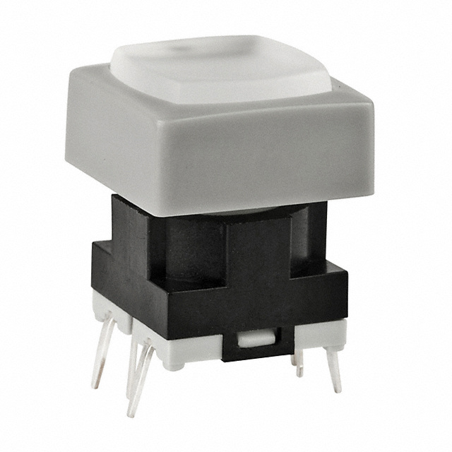
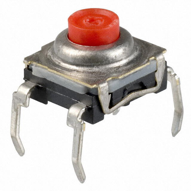
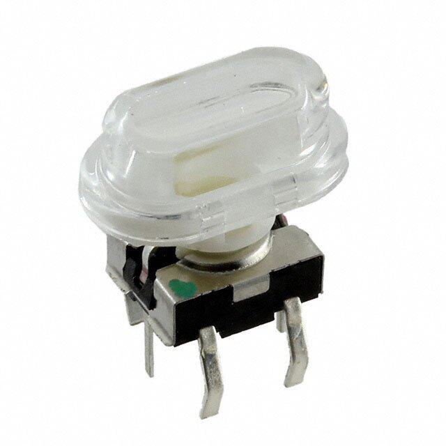
| 描述 | SWITCH TACT SPST-NO 0.125A 24V发光触觉开关 OFF-(ON) HI FRCE GRN LED WHT BTN GRY FRME |
| 产品分类 | |
| 品牌 | NKK Switches |
| 产品手册 | |
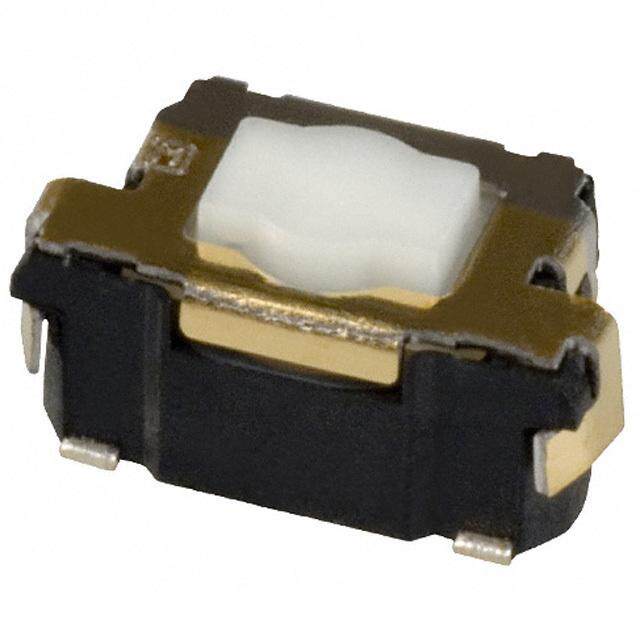
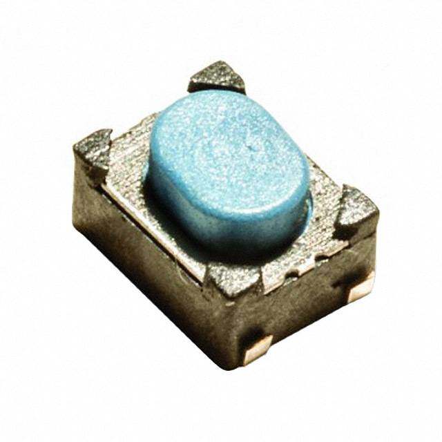
| 产品图片 |
|
| rohs | 符合RoHS无铅 / 符合限制有害物质指令(RoHS)规范要求 |
| 产品系列 | 发光开关,发光触觉开关,NKK Switches JB15HBPF-BHJB |
| mouser_ship_limit | 该产品可能需要其他文件才能进口到中国。 |
| 数据手册 | |
| 产品型号 | JB15HBPF-BH |
| PCB外致动器高度(从引脚计算) | 14.70mm |
| PCN设计/规格 | |
| RoHS指令信息 | |
| 不同电压时的触头额定电流 | 0.125A @ 24VDC |
| 产品培训模块 | http://www.digikey.cn/PTM/IndividualPTM.page?site=cn&lang=zhs&ptm=7079http://www.digikey.cn/PTM/IndividualPTM.page?site=cn&lang=zhs&ptm=30248 |
| 产品种类 | 发光触觉开关 |
| 作用力 | 265gf |
| 侵入防护 | - |
| 包装 | 散装 |
| 商标 | NKK Switches |
| 外形 | 10.00mm x 10.00mm |
| 安装方向 | Straight |
| 安装类型 | 通孔 |
| 安装风格 | Through Hole |
| 工作力 | 2.7 N |
| 工作温度 | -25°C ~ 70°C |
| 工作温度范围 | - 25 C to + 70 C |
| 工厂包装数量 | 1 |
| 开关功能 | OFF - (ON) |
| 开关行程 | 0.30mm |
| 执行器 | Square |
| 接地端子 | No |
| 机械寿命 | 1,000,000 次循环 |
| 标准包装 | 1 |
| 照明 | LED |
| 照明电压(标称值) | 2.1 VDC |
| 照明类型,颜色 | LED,绿 |
| 照明颜色 | Green |
| 特性 | 工艺密封 |
| 电压额定值DC | 24 V |
| 电流额定值 | 125 mA |
| 电路 | SPST-NO |
| 端子类型 | PC 引脚 |
| 端接类型 | Solder Pin |
| 系列 | JB |
| 致动器方向 | 顶部触动 |
| 致动器材料 | 聚对苯二甲酸丁二酯(PBT),玻璃纤维增强型 |
| 致动器类型 | 方形按钮 |
| 行程 | 0.3 mm |
| 触点形式 | SPST |
| 触点电镀 | Silver |
| 颜色 | Gray, White |


- 商务部:美国ITC正式对集成电路等产品启动337调查
- 曝三星4nm工艺存在良率问题 高通将骁龙8 Gen1或转产台积电
- 太阳诱电将投资9.5亿元在常州建新厂生产MLCC 预计2023年完工
- 英特尔发布欧洲新工厂建设计划 深化IDM 2.0 战略
- 台积电先进制程称霸业界 有大客户加持明年业绩稳了
- 达到5530亿美元!SIA预计今年全球半导体销售额将创下新高
- 英特尔拟将自动驾驶子公司Mobileye上市 估值或超500亿美元
- 三星加码芯片和SET,合并消费电子和移动部门,撤换高东真等 CEO
- 三星电子宣布重大人事变动 还合并消费电子和移动部门
- 海关总署:前11个月进口集成电路产品价值2.52万亿元 增长14.8%

PDF Datasheet 数据手册内容提取
Series JB Illuminated Low Profile Process Sealed Tactiles s e gl g General Specifications o T s er k oc Electrical Capacity (Resistive Load) R Low/Logic Level: 50mA @ 24V DC maximum for Standard Operating Force models s 125mA @ 24V DC maximum for High Operating Force models n o utt b h s u Other Ratings P B Standard Operating Force High Operating Force P ed Contact Resistance: 50 milliohms maximum 50 milliohms maximum at n Insulation Resistance: 500 megohms minimum @ 250V DC 500 megohms minimum @ 250V DC mi u Dielectric Strength: 250V AC minimum for 1 minute minimum 250V AC minimum for 1 minute minimum Ill Mechanical Life: 5,000,000 operations minimum 1,000,000 operations minimum e abl Electrical Life: 5,000,000 operations minimum 1,000,000 operations minimum m m Nominal Operating Force: 1.76N for JB15L 2.65N for JB15HL & JB15HB a gr Total Travel: .010” (.254mm) .012” (.300mm) o Pr s Materials & Finishes k c ylo Actuator: Polyacetal for Short; Glass fiber reinforced PBT for Extended e K Case: Glass fiber reinforced polyamide (UL94V-0) Seal: Nitrile butadiene rubber Base: Glass fiber reinforced PBT (UL94V-0) s e ari Movable Contacts: Stainless steel ot Stationary Contacts: Brass with silver plating R Terminals: Brass with silver plating s e Slid Environmental Data Operating Temperature Range: –25°C through +70°C (–13°F through +158°F) Humidity: 90 ~ 95% humidity for 240 hours @ 40°C (104°F) s Vibration: 10 ~ 55Hz with peak-to-peak amplitude of 1.5mm traversing the frequency range & returning e ctil J in 1 minute; 3 right angled directions for 2 hours a T Shock: 50G (490m/s2) acceleration (tested in 6 right angled directions, with 5 shocks in each direction) Tilt PCB Processing Soldering: Wave Soldering recommended. See Profile A in Supplement section. Manual Soldering: See Profile A in Supplement section. Cleaning: Automated cleaning. See Cleaning specifications in Supplement section. h c u o T Standards & Certifications Flammability Standards: UL94V-0 rated case & base ors The JB Series tactiles have not been tested for UL recognition or CSA certification. at These switches are designed for use in a low-voltage, low-current, logic-level circuit. c ndi When used as intended in a logic-level circuit, the results do not produce hazardous energy. I s e ori s s e c c A nt e m e pl p u S J28 www.nkk.com
Series JB Illuminated Low Profile Process Sealed Tactiles s e gl Distinctive Characteristics g o T s er k Choice of dimensions from PCB to top of cap adds to design flexibility. oc R s Bright, full-face illumination with red, green, or yellow LEDs on for attractive, functional panel layouts. butt h s u P B Higher operating force type provides more pronounced P d operating feel. ate n mi u Ill Dome contact gives crisp tactile feedback to positively e bl indicate circuit transfer and assures high reliability ma m and long life of up to 5,000,000 operations. a gr o Pr Rubber seal construction prevents contact contamination s k c and allows automated soldering and cleaning. o yl e K Slanted terminals provide a spring type action which ensures Actual Size s secure mounting and prevents dislodging during wave soldering. arie ot R Molded-in terminals are part of the sealed construction which allows automated soldering and cleaning. s e d Sli Terminal spacing conforms to standard .100” (2.54mm) PCB grid. s e J ctil a T Common Bus Matrix X-Y Matrix These single pole, single throw switches can be used in a key- These single pole, single throw switches can be board matrix and, using strapped terminals, achieve a com- arranged on a single-sided PC board matrix Tilt mon bus electrical configuration on a single-sided PC board. with strapped terminals to achieve an X-Y type electrical interconnection. 5 9 1 2 3 13 PC Terminations 1 2 3 PC Terminations ch u 1 2 3 4 5 6 7 8 9 10111213 1 1 2 3 4 5 6 7 To 1 1 2 2 4 5 6 10 s) 3 4 5 6 s) 3 s 4 6 che 45 2 che 45 cator 7 8 9 11 Swit 67 7 8 9 Swit 67 Indi 3 A 0 B 182 Keys (A890 A 0 B 6 Keys (A890 essories 1 B 7 B cc A = ON = ON 2 7 5 4 3 nt e m Red = PCB Trace Black = Switch Circuit e pl p u S www.nkk.com J29
Series JB Illuminated Low Profile Process Sealed Tactiles s e gl TYPICAL SWITCH ORDERING EXAMPLE g o T s er JB 15 L P C JC k c o R s n o utt b h s u P Pole & Circuit Terminals Cap Types & Colors B d P 15 SPST OFF (ON) P Straight PC Flat Cap Colors e Actuators at ( ) = Momentary B Translucent White n mi L Short u C Red Ill Extended able B (H operating force only) E Yellow m m LED Colors F Green a gr Flat Cap Pro C Red Lens/Diffuser Colors Operating Force E Yellow s JB Clear/White ock No Standard F Green yl Code (L actuator only) JC Clear/Red e K H High JE Clear/Yellow JF Clear/Green s e ari For JC, JE & JF, diffuser ot color must match LED color R Framed Cap Button/Frame Colors s e DESCRIPTION FOR TYPICAL ORDERING EXAMPLE d BB White/White Sli JB15LPC-JC BC White/Red BE White/Yellow s ctile J Flat Cap with BF White/Green Ta Red LED Clear Lens and Red Diffuser BH White/Gray Short Actuator Standard Operating Force Tilt SPST OFF-(ON) Circuit Straight PC Terminals h c u o T POLE & CIRCUIT s or at Actuator Position Switch Throw c ndi ( ) = Momentary & Schematic LED Schematic I s Normal Down e ori Pole & Notes: Terminal numbers ss Throw Model 1 3 are shown on switch. e cc SPST (+) (-) LED circuit is isolated A 2 4 & requires external nt SPST JB15 OFF (ON) power source. e m e pl p u S J30 www.nkk.com
Series JB Illuminated Low Profile Process Sealed Tactiles s e OPERATING FORCE gl g o T No Standard High Code H Nominal Operating Force Nominal Operating Force ers k 1.76N 2.65N oc R Available with short actuator only (code L) Available with both short and extended actuators s n o ACTUATORS utt b h s u P (12.7) Typ L .500 B Short Actuator P d e (11.2) at .441 n (4.9) mi .193 u (.1520.70) Ill (3.1) e (3.0) .122 abl .118 m m a Custom keyboards can be designed with caps installed gr o through a panel cutout (illustration with cap AT4060). Pr s k c o B (.1520.07) Typ eyl Extended Actuator K (3.3) .130 (.83.341) (.1547.79) (12.7) aries .500 ot R (3.2) .126 (3.1) .122 s Custom keyboards can be designed with caps installed de High operating force only through a panel cutout (illustration with cap AT4076). Sli TERMINALS s e J ctil P (.00.381) Typ 3 + 1 Ta Straight PC Terminals (0.3) Typ (5.08) .012 .200 (10.16) (5.08) Typ .400 .200 4 2 (.312.12) Typ ( 2.1.0504) Typ (.10.309) Dia Typ Tilt Further details in Typical Switch Dimensions CL ( 5.2.0080) LED COLORS & SPECIFICATIONS h c u o T LEDs are supplied as an integral part of C E F illuminated devices and are not available s separately. Color Red Yellow Green or at LED polarity markings are on the bottom Forward Peak Current IFM 25mA 25mA 25mA ndic of the switch. I Typical Forward Current I 20mA 20mA 20mA The electrical specifications shown here are F s determined at a basic temperature of 25°C. Forward Voltage VF 2.0V 2.2V 2.1V orie s If the source voltage exceeds the rated volt- Reverse Peak Voltage V 4V 4V 4V es RM c age, a ballast resistor is required. Ac Current Reduction Rate 0.42mA/°C The resistor value can be calculated by using Above 25°C ∆IF nt the formula in the Supplement section. e Ambient Temperature Range –25°C ~ +70°C m e pl p u S www.nkk.com J31
Series JB Illuminated Low Profile Process Sealed Tactiles s e gl SNAP-ON CAPS g o T AT4135 Flat B E ers Cap Color Codes: Translucent White Yellow (7.3) ck .287 o R C F Red Green (12.0) Sq ns .472 o Material: Polycarbonate Finish: Frosted utt b h s u P Framed: PB AT4060 Flat AT4076 Button with Frame d (6.3) (6.3) ate .248 .248 min Lens/Diffuser Translucent Button/Frame u Color Codes: Color Codes: Ille (.1427.20) Sq (.1428.43) Sq bl a m JB BB m Clear/Translucent White White/White a gr o Pr JC BC Clear/Red White/Red s Transparent Translucent ock JE Clear Lens BE Clear Button yl Clear/Yellow White/Yellow e Translucent K White Filter JF Translucent White or BF Opaque White or Clear/Green Colored Diffuser White/Green Colored Frame es White Frame ari BH ot White/Gray R Material: Polycarbonate Lens Finish: Glossy Material: Polycarbonate Button Finish: Frosted s e d Sli TYPICAL SWITCH DIMENSIONS Flat Snap-on Cap s e ctil J (8.5) Ta .335 (.00.146) Short (11.5) Extended (11.5) (10.0) Sq Actuator .453 Actuator .453 .394 Tilt (6.3) (3.1) (6.3) (0.4) (0.3) Typ (0.8) Typ .248 .122 .248 .016 .012 .031 (12.0) Sq (7.0) (4.2) (7.3) (7.4) (3.1) (5.08) .472 .276 .165 .287 .291 .122 .200 h c ou JB15LPC-JC Spring action terminals conform to .100” (2.54mm) PCB spacing T Framed Snap-on Cap s or at (10.0) ndic .394 (.00.146) I s (10.0) Short (11.5) Extended (11.5) (10.0) Sq orie .394 Actuator .453 Actuator .453 .394 s s ce (6.3) (3.1) (6.3) (0.4) (0.3) Typ (0.8) Typ Ac (12.3) Sq .(274.08) (4.2) .122 .2(74.38) .(071.64) (3..01)12 (.50.3018) .484 .276 .165 .287 .291 .122 .200 nt e m ple JB15HBPC-BC Spring action terminals conform to .100” (2.54mm) PCB spacing p u S J32 www.nkk.com
Series JB Illuminated Low Profile Process Sealed Tactiles s e LEGENDS gl g o T NKK Switches can provide custom legends for caps. Contact factory for more information. s er k Suggested Printable Area for Cap, Lens, or Button oc R Recommended Methods: s n o utt b h Laser Etch, Screen Print or Pad Print Laser Etch or Pad Print s u P B P Eisp roexcyo mbamseendd iendk. PWR UP Eisp roexcyo mbamseendd iendk. ON nated mi u Ill e (10.0) Sq bl .394 a m m a gr o Pr s ( 1 .04.1428) Sq ( 0.0.7360) Typ ( 1 .04.1428) Sq ( 0.0.7360) Typ (6.2.9734) ( 0.0.7360) Typ ock (12.0) Sq (12.0) Sq (8.46) yl .472 .472 .333 Ke Shaded areas are printable areas. s e ari ot R Suggested Printable Area for Film Insert s e d Sli Lens (20.0) R .787 s e Film Insert J ctil a T O N Translucent White or (8.38) Typ Colored Diffuser .330 (9.9) .390 Frame Tilt Shaded area is printable area. h c u o T Film Insert: Clear Polyester 7 mil maximum thickness s or at c di n I s e ori s s e c c A nt e m e pl p u S www.nkk.com J33