ICGOO在线商城 > 电感器,线圈,扼流圈 > 固定值电感器 > IHSM4825ER220L
 Datasheet下载
- 型号: IHSM4825ER220L
- 制造商: Vishay
- 库位|库存: xxxx|xxxx
- 要求:
| 数量阶梯 | 香港交货 | 国内含税 |
| +xxxx | $xxxx | ¥xxxx |
查看当月历史价格
查看今年历史价格
IHSM4825ER220L产品简介:
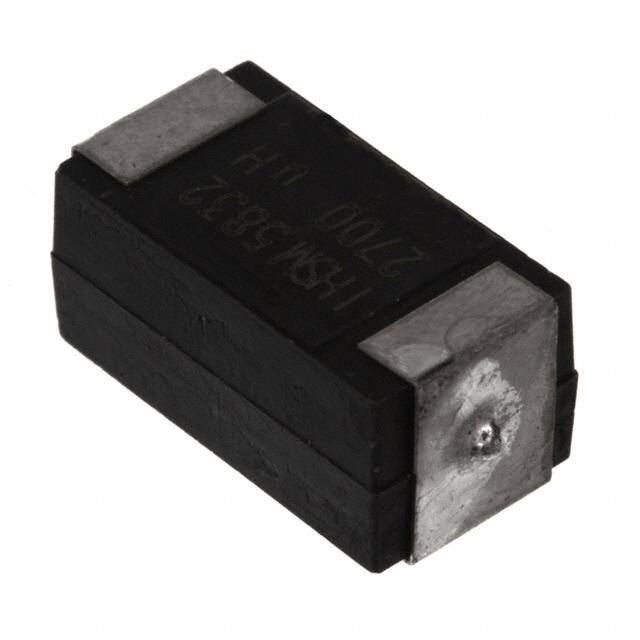
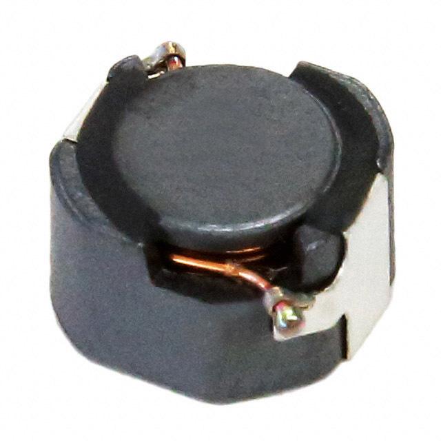
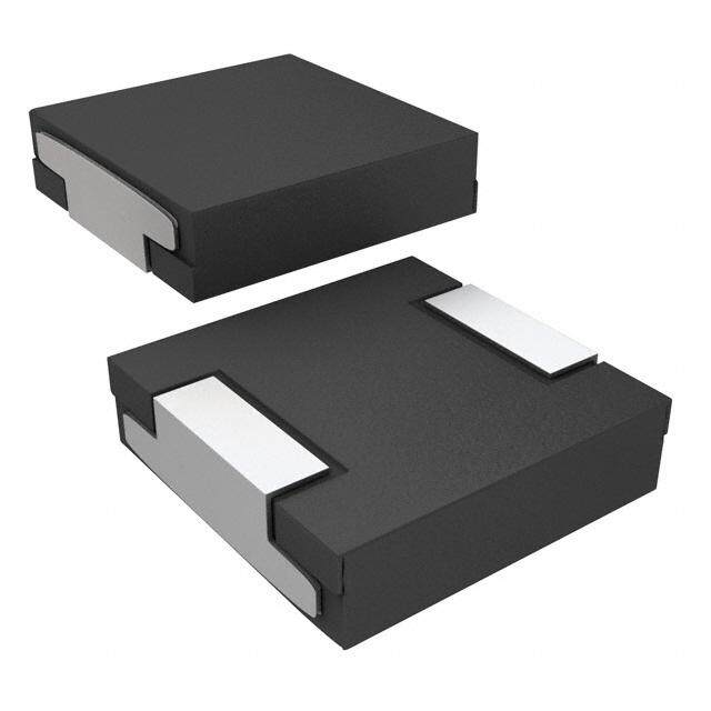
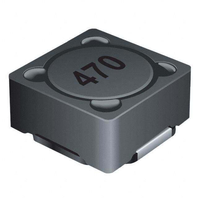
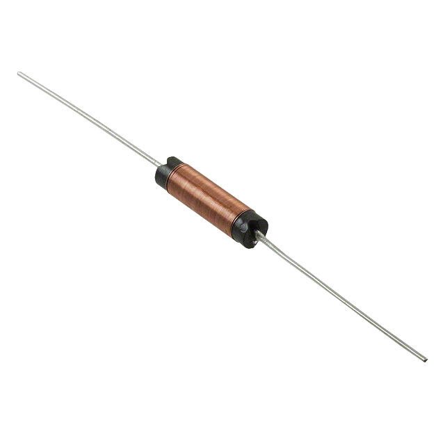
ICGOO电子元器件商城为您提供IHSM4825ER220L由Vishay设计生产,在icgoo商城现货销售,并且可以通过原厂、代理商等渠道进行代购。 IHSM4825ER220L价格参考。VishayIHSM4825ER220L封装/规格:固定值电感器, 22µH 无屏蔽 电感器 1.7A 152 毫欧最大 非标准 。您可以下载IHSM4825ER220L参考资料、Datasheet数据手册功能说明书,资料中有IHSM4825ER220L 详细功能的应用电路图电压和使用方法及教程。
Vishay Dale品牌的IHSM4825ER220L是一款固定值电感器,属于高电流、小型化功率电感器系列。该型号电感器具有较高的电流处理能力和良好的温度稳定性,适用于多种电源管理和转换电路中。

其主要应用场景包括:

1. DC-DC转换器:广泛用于降压(Buck)或升压(Boost)型DC-DC转换器中,作为储能元件,帮助实现电压转换和稳定输出。

2. 电源模块:在模块化电源系统中作为关键的滤波和储能元件,提高电源转换效率和稳定性。

3. 服务器与通信设备电源:用于高可靠性要求的数据中心服务器、路由器和通信基站电源系统中,提供高效、稳定的电流输出。

4. 汽车电子系统:如车载充电系统、电池管理系统(BMS)等,适用于对可靠性与耐温性能有较高要求的汽车应用场景。

5. 工业控制设备:用于工业自动化设备中的开关电源和电机控制电路,提升系统效率和稳定性。

该电感器采用屏蔽结构设计,减少电磁干扰,适合高密度电路布局,是高性能电源设计中的常用元件。
| 参数 | 数值 |
| 产品目录 | |
| DC电阻(DCR) | 152 毫欧最大 |
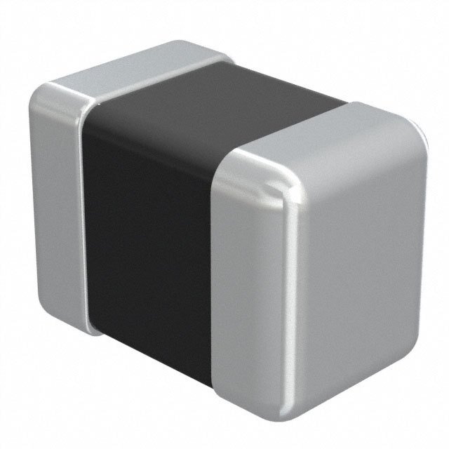
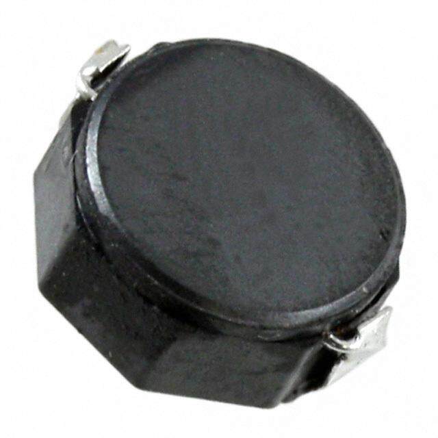
| 描述 | INDUCTOR POWER 22UH 1.7A SMD固定电感器 22uH 15% |
| 产品分类 | |
| 品牌 | Vishay / DaleVishay Dale |
| 产品手册 | |
| 产品图片 |
|
| rohs | RoHS 合规性豁免无铅 / 符合限制有害物质指令(RoHS)规范要求 |
| 产品系列 | 固定电感器,Vishay / Dale IHSM4825ER220LIHSM-4825 |
| 数据手册 | http://www.vishay.com/doc?34019 |
| 产品型号 | IHSM4825ER220LIHSM4825ER220L |
| 不同频率时的Q值 | - |
| 产品 | Inductors |
| 产品目录绘图 |
|
| 产品目录页面 | |
| 产品种类 | High Current Inductors |
| 供应商器件封装 | - |
| 其它名称 | 541-1038-6 |
| 包装 | Digi-Reel® |
| 商标 | Vishay / Dale |
| 外壳宽度 | 6.35 mm |
| 外壳长度 | 13.72 mm |
| 外壳高度 | 5.72 mm |
| 大小/尺寸 | 0.540" 长x 0.250" 宽(13.72mm x 6.35mm) |
| 安装类型 | 表面贴装 |
| 容差 | ±15%15 % |
| 封装 | Reel |
| 封装/外壳 | 非标准 |
| 封装/箱体 | 4825 |
| 屏蔽 | 无屏蔽Unshielded |
| 工作温度 | -55°C ~ 125°C |
| 工作温度范围 | - 55 C to + 125 C |
| 工厂包装数量 | 750 |
| 最大直流电流 | 1.7 A |
| 最大直流电阻 | 152 mOhms |
| 材料-磁芯 | 铁氧体 |
| 标准包装 | 1 |
| 测试频率 | 1 kHz |
| 电感 | 22 uH22µH |
| 电流-饱和值 | 1.02A |
| 端接类型 | SMD/SMT |
| 类型 | -High Current Surface Mount Inductor |
| 系列 | IHSM-4825 |
| 芯体材料 | Ferrite |
| 频率-测试 | 1kHz |
| 频率-自谐振 | - |
| 额定电流 | 1.7A |
| 高度-安装(最大值) | 0.225" (5.72mm) |


%20Series%20End.jpg)


- 商务部:美国ITC正式对集成电路等产品启动337调查
- 曝三星4nm工艺存在良率问题 高通将骁龙8 Gen1或转产台积电
- 太阳诱电将投资9.5亿元在常州建新厂生产MLCC 预计2023年完工
- 英特尔发布欧洲新工厂建设计划 深化IDM 2.0 战略
- 台积电先进制程称霸业界 有大客户加持明年业绩稳了
- 达到5530亿美元!SIA预计今年全球半导体销售额将创下新高
- 英特尔拟将自动驾驶子公司Mobileye上市 估值或超500亿美元
- 三星加码芯片和SET,合并消费电子和移动部门,撤换高东真等 CEO
- 三星电子宣布重大人事变动 还合并消费电子和移动部门
- 海关总署:前11个月进口集成电路产品价值2.52万亿元 增长14.8%

PDF Datasheet 数据手册内容提取
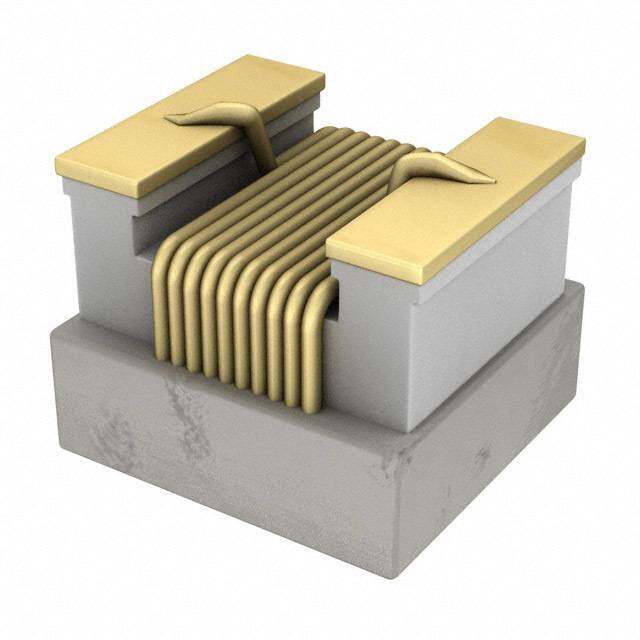
IHSM-4825 www.vishay.com Vishay Dale High Current, Surface Mount Inductors - Wirewound Molded FEATURES • Flame retardant encapsulant (UL 94 V-0) • Completely encapsulated winding provides superior environmental protection and moisture resistance • High current unit in surface mount package printed with model, inductance value and date code • Compatible with infrared or conventional reflow soldering STANDARD ELECTRICAL SPECIFICATIONS methods • Pick and place compatible IND. DCR RATED INCREMENTAL • Tape and reel packaging for automatic handling AT 1 kHz MAX. CURRENT MAX. CURRENT APPROX. • Material categorization: For definitions of compliance (μH) () (A) (A) please see www.vishay.com/doc?99912 1.0 0.013 8.6 4.1 APPLICATIONS 1.2 0.018 7.6 3.8 Excellent power line noise filters, filters for switching 1.5 0.02 6.9 3.5 regulated power supplies, DC/DC converters, SCR and triac 1.8 0.021 6.5 3.2 controls and RFI suppression. 2.2 0.029 5.7 2.9 ELECTRICAL SPECIFICATIONS 2.7 0.034 5.1 2.6 Inductance: Measured at 1 V with no DC current 3.3 0.038 4.6 2.4 Inductance Tolerance: ± 15 % 3.9 0.042 4.3 2.2 Incremental Current: The typical current at which the 4.7 0.047 4.0 2.0 inductance will be decreased by 5 % from its initial zero DC 5.6 0.051 3.8 1.9 value 6.8 0.058 3.5 1.7 Operating Temperature: -55 °C to +125 °C (no load); 8.2 0.063 3.3 1.5 -55 °C to +85 °C (at full rated current) 10.0 0.071 3.1 1.4 MECHANICAL SPECIFICATIONS 12.0 0.079 2.7 1.3 Core: High resistivity ferrite core 15.0 0.089 2.3 1.2 Encapsulant: Epoxy 18.0 0.119 1.9 1.1 Terminals: 100 % Sn over Ni 22.0 0.152 1.7 1.02 DIMENSIONS in inches [millimeters] 27.0 0.179 1.6 0.95 33.0 0.222 1.3 0.88 0.660 [16.764] Recommended Pad Layout 39.0 0.315 1.19 0.8 47.0 0.362 1.07 0.74 0.220 0.220 56.0 0.397 0.95 0.68 [5.588] 0.300 [7.62] [5.588] 68.0 0.446 0.87 0.62 82.0 0.604 0.8 0.56 0.180 [4.572] 0.180 [4.572] 100.0 0.672 0.73 0.5 0.540 [13.72] 0.170 ± 0.010 120.0 0.735 0.66 0.45 Max. [4.32 ± 0.25] 150.0 0.998 0.58 0.4 0.225 180.0 1.37 0.5 0.35 [5.72] Max. 220.0 1.58 0.46 0.32 270.0 1.77 0.41 0.3 0.075 ± 0.010 [1.91 ± 0.25] 330.0 2.51 0.37 0.28 0.480 ± 0.020 0.25M0a [x6..35] 390.0 2.73 0.34 0.26 [12.19 ± 0.51] 470.0 3.36 0.32 0.24 PART MARKING 560.0 3.75 0.3 0.23 680.0 4.31 0.28 0.2 - Model - Inductance value 820.0 6.04 0.26 0.17 - Date code 1000.0 6.9 0.24 0.15 DESCRIPTION IHSM-4825 3.9 μH ± 15 % ER e3 MODEL INDUCTANCE VALUE INDUCTANCE TOLERANCE PACKAGE CODE JEDEC LEAD (Pb)-FREE STANDARD GLOBAL PART NUMBER I H S M 4 8 2 5 E R 3 R 9 L PRODUCT FAMILY SIZE PACKAGE INDUCTANCE TOL. CODE VALUE Revision: 20-Sep-13 1 Document Number: 34019 For technical questions, contact: magnetics@vishay.com THIS DOCUMENT IS SUBJECT TO CHANGE WITHOUT NOTICE. THE PRODUCTS DESCRIBED HEREIN AND THIS DOCUMENT ARE SUBJECT TO SPECIFIC DISCLAIMERS, SET FORTH AT www.vishay.com/doc?91000
Legal Disclaimer Notice www.vishay.com Vishay Disclaimer ALL PRODUCT, PRODUCT SPECIFICATIONS AND DATA ARE SUBJECT TO CHANGE WITHOUT NOTICE TO IMPROVE RELIABILITY, FUNCTION OR DESIGN OR OTHERWISE. Vishay Intertechnology, Inc., its affiliates, agents, and employees, and all persons acting on its or their behalf (collectively, “Vishay”), disclaim any and all liability for any errors, inaccuracies or incompleteness contained in any datasheet or in any other disclosure relating to any product. Vishay makes no warranty, representation or guarantee regarding the suitability of the products for any particular purpose or the continuing production of any product. To the maximum extent permitted by applicable law, Vishay disclaims (i) any and all liability arising out of the application or use of any product, (ii) any and all liability, including without limitation special, consequential or incidental damages, and (iii) any and all implied warranties, including warranties of fitness for particular purpose, non-infringement and merchantability. Statements regarding the suitability of products for certain types of applications are based on Vishay’s knowledge of typical requirements that are often placed on Vishay products in generic applications. Such statements are not binding statements about the suitability of products for a particular application. It is the customer’s responsibility to validate that a particular product with the properties described in the product specification is suitable for use in a particular application. Parameters provided in datasheets and / or specifications may vary in different applications and performance may vary over time. All operating parameters, including typical parameters, must be validated for each customer application by the customer’s technical experts. Product specifications do not expand or otherwise modify Vishay’s terms and conditions of purchase, including but not limited to the warranty expressed therein. Except as expressly indicated in writing, Vishay products are not designed for use in medical, life-saving, or life-sustaining applications or for any other application in which the failure of the Vishay product could result in personal injury or death. Customers using or selling Vishay products not expressly indicated for use in such applications do so at their own risk. Please contact authorized Vishay personnel to obtain written terms and conditions regarding products designed for such applications. No license, express or implied, by estoppel or otherwise, to any intellectual property rights is granted by this document or by any conduct of Vishay. Product names and markings noted herein may be trademarks of their respective owners. © 2017 VISHAY INTERTECHNOLOGY, INC. ALL RIGHTS RESERVED Revision: 08-Feb-17 1 Document Number: 91000