ICGOO在线商城 > 连接器,互连器件 > 存储器连接器 - PC 卡插槽 > IC11SA-PLR-SF-EJR(71)
.jpg)
 Datasheet下载
- 型号: IC11SA-PLR-SF-EJR(71)
- 制造商: Hirose Electric
- 库位|库存: xxxx|xxxx
- 要求:
| 数量阶梯 | 香港交货 | 国内含税 |
| +xxxx | $xxxx | ¥xxxx |
查看当月历史价格
查看今年历史价格
IC11SA-PLR-SF-EJR(71)产品简介:
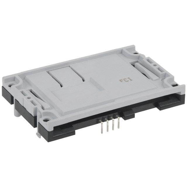
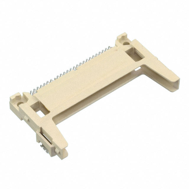
ICGOO电子元器件商城为您提供IC11SA-PLR-SF-EJR(71)由Hirose Electric设计生产,在icgoo商城现货销售,并且可以通过原厂、代理商等渠道进行代购。 IC11SA-PLR-SF-EJR(71)价格参考¥35.58-¥35.58。Hirose ElectricIC11SA-PLR-SF-EJR(71)封装/规格:存储器连接器 - PC 卡插槽, 68 Position Card Connector PCMCIA - CardBus, Type I, II, III Surface Mount, Right Angle Gold。您可以下载IC11SA-PLR-SF-EJR(71)参考资料、Datasheet数据手册功能说明书,资料中有IC11SA-PLR-SF-EJR(71) 详细功能的应用电路图电压和使用方法及教程。
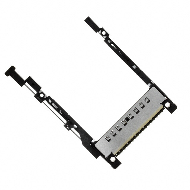
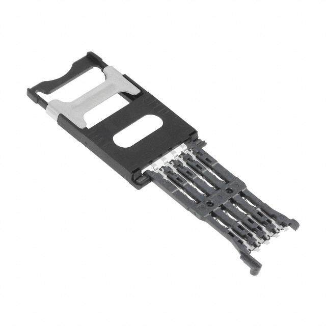
Hirose Electric Co Ltd的IC11SA-PLR-SF-EJR(71)是一款PC卡插槽连接器,主要用于工业控制设备、测量仪器、数据采集系统等需要稳定存储扩展的场景。该连接器支持PC卡(PCMCIA)接口,适用于需要高可靠性和稳定连接的工业环境。典型应用包括自动化设备、测试仪器、便携式终端设备以及嵌入式系统等。其紧凑设计和高耐用性也使其适用于空间受限但对连接稳定性有较高要求的场合。
| 参数 | 数值 |
| 产品目录 | |
| 描述 | CONN PCMCIA CARD PUSH-PUSH R/A |
| 产品分类 | 存储器连接器 - PC 卡 |
| 品牌 | Hirose Electric Co Ltd |
| 数据手册 | |
| 产品图片 |
|
| 产品型号 | IC11SA-PLR-SF-EJR(71) |
| rohs | 无铅 / 符合限制有害物质指令(RoHS)规范要求 |
| 产品系列 | IC11S |
| 产品目录绘图 |
|
| 产品目录页面 | |
| 其它名称 | *IC11SA-PLR-SF-EJR(71) |
| 包装 | 散装 |
| 卡类型 | PCMCIA - CardBus,I 型、II 型、III 型 |
| 安装特性 | 反向 - 底部 |
| 安装类型 | 表面贴装,直角 |
| 弹出器端 | 右侧 |
| 插入,拆除方法 | 推入式,推出式 |
| 板上高度 | 0.307"(7.80mm) |
| 标准包装 | 24 |
| 特性 | 板导轨,卡导轨 |
| 触头镀层 | 金 |
| 触头镀层厚度 | - |
| 连接器类型 | 连接器和弹出器 |
| 针脚数 | 68 |
.JPG)


- 商务部:美国ITC正式对集成电路等产品启动337调查
- 曝三星4nm工艺存在良率问题 高通将骁龙8 Gen1或转产台积电
- 太阳诱电将投资9.5亿元在常州建新厂生产MLCC 预计2023年完工
- 英特尔发布欧洲新工厂建设计划 深化IDM 2.0 战略
- 台积电先进制程称霸业界 有大客户加持明年业绩稳了
- 达到5530亿美元!SIA预计今年全球半导体销售额将创下新高
- 英特尔拟将自动驾驶子公司Mobileye上市 估值或超500亿美元
- 三星加码芯片和SET,合并消费电子和移动部门,撤换高东真等 CEO
- 三星电子宣布重大人事变动 还合并消费电子和移动部门
- 海关总署:前11个月进口集成电路产品价值2.52万亿元 增长14.8%

PDF Datasheet 数据手册内容提取
Single Slot SMT Connectors For Card-Bus Based PC Cards IC11S Series PC Card Standard Compliant Reduced height : 5.6mm high (cid:5) Features Wide variety of options 1. PC Card Standard compliant: (1)Board Mounting ➀ Standard type • Grounding is required to meet the high speed signal ➁ requrements of the PC card standard. Grounding reliability is Reverse type achieved with a grounding plate and 8 grounding contacts. (2)Types of eject button •Type 1, type 2 and type 3 cards are covered. ➀ • Terminals for ground clipping are provided. Rigid button ➁ Foldering button 2. Space saving ➂ Pop-up button Smaller size reduces occupied area on PC boards as (3)Position of eject buttons compared to previous products. ➀ Right 3. Reduced Height: ➁ Left Connector height is minimized to 5.6mm, making possible (4)Standoffs thinner product designs. ➀ None 4. Eject mechanism with high-level functionality ➁ 2.2mm Hirose Electric's original ejection mechanism provides an higher degree of card ejection over existing products. This improves the operational qualities of card removal. (Patents pending) 5. Wide Variety of Options Available • Standard type mounts to the top of the PC board and reverse type mounts on the underside of the board • Three types of eject buttons; rigid, flexible and POP-UP.All types can be installed on the right or left side of the ejector. • Available with standoff to utilize space under the connector for mounting other parts. 6. Light-weight Weight of 12.7g for normal button type helps achieve the reduced weight required in today’s products. A2
(cid:5) Product Specifications Current rating 0.5A Operating temperature -55ç to +85ç(Note.1) Storage temperature -40ç to +70ç(Note.2) Ratings Relativehumidity 95% max. Voltage rating 125V AC Operating humidity Storage humidity 40%to 70%(Note.2) (With no dew-fall) Item Specification Conditions 1.Insulation resistance 1000Mohms min. 500V DC 2.Withstanding voltage No flashover or insulation breakdown. 500V AC 3.Contact resistance 60mohms max. (initial value) 1mA Frequency: 10 to 2000 Hz, full amplitude of 1.52 mm or 4.Vibration No electrical discontinuity of 100ns or more acceleration of 147 m/s2(peak), 4 hours in each of the 3 directions. 5.Humidity (Steady state) Insulation resistance: 100Mohms min. 96 hours at temperature of 40ç and humidity of 90% to 95% (-55ç:30min./+5ç to 35ç:MAX 5min/85ç:30min/+5 6.Temperature cycle Insulation resistance: 100Mohms min. -35ç:MAX 5min.) 5 cycles 7.Durability Variations from initial contact resistance: 20m 10000 cycles at 400 to 600 cycles per hour (Insertion/withdrawal) ohmsmax. 8.Resistance to No deformation of components affecting Reflow: At the recommended temperature profile Soldering heat performance. Manual soldering: 300ç for 3 seconds Note 1: Includes temperature rise caused by current flow. Note 2: The term "storage" refers to products stored for long period of time prior to mounting and use. Operating Temperature Range and Humidity range covers non- conducting condition of installed connectors in storage, shipment or during transportation. (cid:5) Material SMT unit Parts Material Finish Remarks Insulator PPS Black UL94V-0 Contact section: gold plating Card connected section Brass ---------- Lead section: solder plating Contact Contact section: gold plating Ground plate Phosphor bronze ---------- Lead section: solder plating Eject metal fittings Stainless steel ---------- ---------- Guide unit Item Material Finish Remarks Guide plate Stainless steel ---------- ---------- Push rod Stainless steel ---------- ---------- Rigid button type resin section PBT Color : Black UL94V-0 resin section PBT Color : Black UL94V-0 Foldering spring Stainless steel ---------- ---------- button type spring pin Stainless steel ---------- ---------- Eject Button resin section PBT Color : Black UL94V-0 frame metal Stainless steel ---------- ---------- POP-UP type spring Steel ---------- ---------- pin Brass Nickel plating ---------- Nut Steel ---------- M2X0.4 A3
(cid:5) Ordering Information SMT Unit IC11S A - 68 PLR - 1.27SF - EJ R 1 2 3 4 5 6 7 1 Series name : IC11S 5 1.27SF : 1.27mm pitch SMT connector 2 Standoff type Blank : none A : 2.2mm 6 With ejector EJ : with ejector 3 Number of contacts : 68 4 Board Mounting Type: 7 Eject button positions PL : standard type R : right PLR : reverse type L : left Guide Unit IC11S A - BUR - FEJ R 8 9 10 11 12 8 Series name : IC11S 11 Eject button type EJ : rigid button 9 Standoff type FEJ : Foldering button Blank: none PEJ : POP-UP button A : 2.2mm 10 Board Mounting Type 12 Eject button positions BD : standard type R : right BUR : reverse type L : left (Note.)IC11S Series will be used in combination of SMT unit with guide unit. When using, please select the same type for the following items. Please note that other combinations cannot be used. • Series name ( 1 ⇔8) • Standoff ( 2 ⇔9) • Board-installed type ( 4 ⇔10) • Eject button positions ( 7 ⇔12) A4
(cid:5) Standard Right rigid button type 34.4 MAX 3 59 42.545 P=0.635 SMT unit ( 1 ) No.1 No.35 No.2 No.68 eject metal fittings movable range GND GND C No.36 No.34 7.4 MAX 7 X A M 0.5 10 2 A P U S H P U S H 5 1. 5 n o 72 serti n 5.9 3 59.5 card i n 6: i 5. 8 6) 7. 8.6) (2 3 54.9 (1 6 e:9 k o guide unit ( 2 ) (34.9) str No.1 No.2 No.34 8 B 4. A No.35 No.36 No.68 ➀ ➁ SMT unit Guide unit Standoff A B C Weight type Part Number CL No. Part Number CL No. (mm) (mm) (mm) (g) none IC11S-68PL-1.27SF-EJR 640-1007-3 IC11S-BD-EJR 640-1071-2 3 5.6 0.1 12.7 2.2mm IC11SA-68PL-1.27SF-EJR 640-1009-9 IC11SA-BD-EJR 640-1073-8 5.2 7.8 2.3 13.1 Note.1) This figure illustrates grouping of SMT unit(➀ ) and guide unit(➁ ) together. Note.2) Dimensions for card fitting are in accordance with "PC Card Standard". Note.3) Indicated dimensions are symmetrical to the center of the card insertion slot. A5
(cid:5) Standard Left rigid button type 34.4MAX 3 59 SMT unit ( 1 ) 42.545 P= 0.635 No.1 No.35 No.68 C eject metal fittings movable range GND No.2 No.34 GND No.36 X A 4 M 7. 7 X A M 0 1 5 A 20. P U S H P U S H 5 1. 5 n ertio 72 s d in 3 59.5 n car 5.9 6: i 5. 8 6) 7. (2 6) 8. (1 3 54.9 e:9 6 k o str (34.9) guide unit ( 2 ) No.1 No.2 No.34 8 4. A B No.35 No.36 No.68 ➀ ➁ SMT unit Guide unit Standoff A B C Weight type Part Number CL No. Part Number CL No. (mm) (mm) (mm) (g) none IC11S-68PL-1.27SF-EJL 640-1008-6 IC11S-BD-EJL 640-1072-5 3 5.6 0.1 12.7 2.2mm IC11SA-68PL-1.27SF-EJL 640-1010-8 IC11SA-BD-EJL 640-1074-0 5.2 7.8 2.3 13.1 ➀ ➁ Note.1) This figure illustrates grouping of SMT unit( ) and guide unit( ) together. Note.2) Dimensions for card fitting are in accordance with "PC Card Standard". Note.3) Indicated dimensions are symmetrical to the center of the card insertion slot. A6
(cid:5) Standard Right flexible button type 34.4 MAX 59 42.545 P=0.635 SMT unit ( 1 ) No.35 No.1 No.2 No.68 eject metal fittings movable range C GND No.36 No.34 GND X 4 A 7. M 7 X A M 0 5 1 20. A P U S H P U S H 5 1. 5 72 ertion ection 5.9 3 59.5 85.6: in card ins (93.6): in card ej 6) 7. 8.6) (2 3 54.9 (1 A 5 5) 0. 1 guide unit ( 2 ) st volume( stroke:9 u hr n t o utt b (34.55) (42.05) No.1 No.2 No.34 8 B A 4. No.35 No.36 No.68 ➀ ➁ SMT unit Guide unit Standoff A B C Weight type Part Number CL No. Part Number CL No. (mm) (mm) (mm) (g) none IC11S-68PL-1.27SF-EJR 640-1007-3 IC11S-BD-FEJR 640-1075-3 3 5.6 0.1 13.1 2.2mm IC11SA-68PL-1.27SF-EJR 640-1009-9 IC11SA-BD-FEJR 640-1077-9 5.2 7.8 2.3 13.5 ➀ ➁ Note.1) This figure illustrates grouping of SMT unit( ) and guide unit( ) together. Note.2) Dimensions for card fitting are in accordance with "PC Card Standard". Note.3) Indicated dimensions are symmetrical to the center of the card insertion slot. A7
(cid:5) Standard Left flexible. button type 34.4MAX 3 59 SMT unit ( 1 ) 42.545 P=0.635 No.1 No.35 No.68 No.2 C eject metal fittings movable range GND No.34 GND No.36 X 7 MA 7.4 X A M 0 1 5 A 20. P U S H P U S H 5 1. 5 ection ertion 3 59.5 72 card ej ard ins 5.9 (93.6): in 85.6: in c 6) 7. (2 8.6) (1 3 54.9 5 stroke:9 button thrust volume(10.5) guide unit ( 2 ) (34.55) (42.05) No.1 No.2 No.34 8 4. A B No.35 No.36 No.68 ➀ ➁ SMT unit Guide unit Standoff A B C Weight type Part Number CL No. Part Number CL No. (mm) (mm) (mm) (g) none IC11S-68PL-1.27SF-EJL 640-1008-6 IC11S-BD-FEJL 640-1076-6 3 5.6 0.1 13.1 2.2mm IC11SA-68PL-1.27SF-EJL 640-1010-8 IC11SA-BD-FEJL 640-1078-1 5.2 7.8 2.3 13.5 ➀ ➁ Note.1) This figure illustrates grouping of SMT unit( ) and guide unit( ) together. Note.2) Dimensions for card fitting are in accordance with "PC Card Standard". Note.3) Indicated dimensions are symmetrical to the center of the card insertion slot. A8
(cid:5) Standard Right POP-UP button type 34.4 MAX 3 59 42.545 P=0.635 SMT unit ( 1 ) No.1 No.35 No.2 No.68 eject metal fittings movable range GND GND C No.36 No.34 X 4 A 7. M 7 X A M 0 5 1 20. A P U S H P U S H A 5 1. 5 72 5.9 DR 3 59.5 84.5(button thrust position) 86.4(button stored position) 3 54.9 guide unit ( 2 ) e) m 5 u ol v p u p- (35.1) o P 1( 9. No.1 No.2 No.34 B 5 A No.35 No.36 No.68 ➀ ➁ SMT unit Guide unit Standoff A B C Weight type Part Number CL No. Part Number CL No. (mm) (mm) (mm) (g) none IC11S-68PL-1.27SF-EJR 640-1007-3 IC11S-BD-PEJR 640-1081-6 3 5.7 0.1 14.7 2.2mm IC11SA-68PL-1.27SF-EJR 640-1009-9 IC11SA-BD-PEJR 640-1083-1 5.2 7.9 2.3 15.1 ➀ ➁ Note.1) This figure illustrates grouping of SMT unit( ) and guide unit( ) together. Note.2) Dimensions for card fitting are in accordance with "PC Card Standard". Note.3) Indicated dimensions are symmetrical to the center of the card insertion slot. A9
(cid:5) Standard Left POP-UP button type 34.4 MAX 3 59 SMT unit ( 1 ) 42.545 P=0.635 No.1 No.35 No.68 C eject metal fittings movable range GND No.2 No.34 GND No.36 AX 4 M 7. 7 X A M 0 1 5 A 20. P U S H P U S H 5 1. 5 86.4(button stored position) 84.5(button thrust position) 3 59.5 DL 5.9 72 3 54.9 e) m u 5 vol guide unit ( 2 ) p u p- o P 1( (35.1) 9. No.1 No.2 No.34 5 B A No.35 No.36 No.68 ➀ ➁ SMT unit Guide unit Standoff A A C Weight type Part Number CL No. Part Number CL No. (mm) (mm) (mm) (g) none IC11S-68PL-1.27SF-EJL 640-1008-6 IC11S-BD-PEJL 640-1082-9 3 5.7 0.1 14.7 2.2mm IC11SA-68PL-1.27SF-EJL 640-1010-8 IC11SA-BD-PEJL 640-1084-4 5.2 7.9 2.3 15.1 ➀ ➁ Note.1) This figure illustrates grouping of SMT unit( ) and guide unit( ) together. Note.2) Dimensions for card fitting are in accordance with "PC Card Standard". Note.3) Indicated dimensions are symmetrical to the center of the card insertion slot. A10
(cid:5) Reverse Right rigid button type 34.4 MAX 3 59 42.545 SMT unit ( 1 ) P=0.635 No.35 No.68 No.34 No.1 eject metal fittings movable range No.2 GND GND C No.36 X A 6 M 7 X A M 0 5 1 20. A P U S H P U S H 5 1. 5 n 72 ertio s n 5.9 3 59.5 ard i c n 6: i 5. 8 6) 7. 6) (2 8. 1 ( 3 54.9 6 e:9 k (34.9) stro guide unit ( 2 ) No.68 No.36 No.35 8 B A 4. No.34 No.2 No.1 ➀ ➁ SMT unit Guide unit Standoff A B C Weight type Part Number CL No. Part Number CL No. (mm) (mm) (mm) (g) none IC11S-68PLR-1.27SF-EJR 640-1003-2 IC11S-BUR-EJR 640-1055-6 2.7 5.6 0.1 13.1 2.2mm IC11SA-68PLR-1.27SF-EJR 640-1005-8 IC11SA-BUR-EJR 640-1057-1 4.9 7.8 2.3 13.6 ➀ ➁ Note.1) This figure illustrates grouping of SMT unit( ) and guide unit( ) together. Note.2) Dimensions for card fitting are in accordance with "PC Card Standard". Note.3) Indicated dimensions are symmetrical to the center of the card insertion slot. A11
(cid:5) Reverse Left rigid button type 34.4 MAX 3 59 42.545 P=0.635 SMT unit ( 1 ) No.68 No.35 No.1 eject metal fittings movable range No.2 C GND No.34 No.36 GND X A M 6 7 X A M 0 1 5 A 20. P U S H P U S H 5 1. 5 2 n 7 o erti 3 59.5 s ard in 5.9 c n 6: i 5. 8 6) 7. (2 8.6) (1 3 54.9 6 (34.9) guide unit ( 2 ) No.36 No.35 No.68 8 4. A B No.34 No.2 No.1 ➀ ➁ SMT unit Guide unit Standoff A B C Weight type Part Number CL No. Part Number CL No. (mm) (mm) (mm) (g) none IC11S-68PLR-1.27SF-EJL 640-1004-5 IC11S-BUR-EJL 640-1056-9 2.7 5.6 0.1 13.1 2.2mm IC11SA-68PLR-1.27SF-EJL 640-1006-0 IC11SA-BUR-EJL 640-1058-4 4.9 7.8 2.3 13.6 ➀ ➁ Note.1) This figure illustrates grouping of SMT unit( ) and guide unit( ) together. Note.2) Dimensions for card fitting are in accordance with "PC Card Standard". Note.3) Indicated dimensions are symmetrical to the center of the card insertion slot. A12
(cid:5) Reverse Right flexible button type 34.4 MAX 3 59 42.545 P=0.635 SMT unit ( 1 ) No.68 No.35 No.1 eject metal fittings movable range GND No.34 No.2 GND C No.36 X A 6 M 7 X A M 0 5 1 20. A P U S H P U S H 5 1. 5 72 3 59.5 nsertion ejection 5.9 85.6: in card i 93.6: in card 6) 7. 8.6) (2 3 54.9 (1 A 5 guide unit ( 2 ) st :(10.5) stroke:9 u hr n t o utt b (34.55) (42.05) No.68 No.36 No.35 8 B A 4. No.34 No.2 No.1 ➀ ➁ SMT unit Guide unit Standoff A B C Weight type Part Number CL No. Part Number CL No. (mm) (mm) (mm) (g) none IC11S-68PLR-1.27SF-EJR 640-1003-2 IC11S-BUR-FEJR 640-1059-7 2.7 5.6 0.1 13.5 2.2mm IC11SA-68PLR-1.27SF-EJR 640-1005-8 IC11SA-BUR-FEJR 640-1061-9 4.9 7.8 2.3 14 ➀ ➁ Note.1) This figure illustrates grouping of SMT unit( ) and guide unit( ) together. Note.2) Dimensions for card fitting are in accordance with "PC Card Standard". Note.3) Indicated dimensions are symmetrical to the center of the card insertion slot. A13
(cid:4) Reverse Left flexible button type 34.4 MAX 3 59 42.545 eject metal fittings movable range P=0.635 No.68 No.35 No.1 SMT unit ( 1 ) No.34 GND No.2 C GND No.36 X A M 6 7 X A M 0 1 5 0. A 2 P U S H P U S H 5 1. 5 ejection nsertion 3 59.5 72 93.6: in card 85.6: in card i 5.9 ) 6 27. 6) ( 8. (1 3 54.9 5 5) stroke:9 hrust :(10. guide unit ( 2 ) n t o utt b (34.55) (42.05) No.68 No.36 No.35 8 4. B A No.34 No.2 No.1 ➀ ➁ SMT unit Guide unit Standoff A B C Weight type Part Number CL No. Part Number CL No. (mm) (mm) (mm) (g) none IC11S-68PLR-1.27SF-EJL 640-1004-5 IC11S-BUR-FEJL 640-1060-6 2.7 5.6 0.1 13.5 2.2mm IC11SA-68PLR-1.27SF-EJL 640-1006-0 IC11SA-BUR-FEJL 640-1062-1 4.9 7.8 2.3 14 ➀ ➁ Note.1) This figure illustrates grouping of SMT unit( ) and guide unit( ) together. Note.2) Dimensions for card fitting are in accordance with "PC Card Standard". Note.3) Indicated dimensions are symmetrical to the center of the card insertion slot. A14
(cid:4) Reverse Right POP-UP button type 34.4 MAX 3 59 42.545 SMT unit ( 1 ) P=0.635 No.35 No.68 No.34 No.1 eject metal fittings movable range No.2 GND GND C No.36 X A 6 M 7 X A M 0 5 1 20. A P U S H P U S H A 5 1. 5 72 5.9 3 59.5 hrust position) ored position) UR 84.5(button t 86.4(button st 3 54.9 e) m guide unit ( 2 ) 5 u ol v p u p- (35.1) Po 1( 9. No.68 No.36 No.35 B 5 A No.34 No.2 No.1 ➀ ➁ SMT unit Guide unit Standoff A B C Weight type Part Number CL No. Part Number CL No. (mm) (mm) (mm) (g) none IC11S-68PLR-1.27SF-EJR 640-1003-2 IC11S-BUR-PEJR 640-1065-0 2.7 5.6 0.1 15.1 2.2mm IC11SA-68PLR-1.27SF-EJR 640-1005-8 IC11SA-BUR-PEJR 640-1067-5 4.9 7.8 2.3 15.6 ➀ ➁ Note.1) This figure illustrates grouping of SMT unit( ) and guide unit( ) together. Note.2) Dimensions for card fitting are in accordance with "PC Card Standard". Note.3) Indicated dimensions are symmetrical to the center of the card insertion slot. A15
(cid:4) Reverse Left POP-UP button type 34.4MAX 3 59 42.545 P=0.635 SMT unit ( 1 ) No.68 No.35 No.1 eject metal fittings movable range No.2 C GND No.34 No.36 GND X MA 6 7 X A M 10 A 20.5 P U S H P U S H 5 1. 86.4(button stored position) 84.5(button thrust position) 3 59.5 UL 5.9 5 72 e) m 5 guide unit ( 2 ) u ol v p u p- o P (35.1) 1( 9. No.36 No.35 No.68 5 B A No.34 No.2 No.1 ➀ ➁ SMT unit Guide unit Standoff A B C Weight type Part Number CL No. Part Number CL No. (mm) (mm) (mm) (g) none IC11S-68PLR-1.27SF-EJL 640-1004-5 IC11S-BUR-PEJL 640-1066-2 2.7 5.6 0.1 15.1 2.2mm IC11SA-68PLR-1.27SF-EJL 640-1006-0 IC11SA-BUR-PEJL 640-1068-8 4.9 7.8 2.3 15.6 ➀ ➁ Note.1) This figure illustrates grouping of SMT unit( ) and guide unit( ) together. Note.2) Dimensions for card fitting are in accordance with "PC Card Standard". Note.3) Indicated dimensions are symmetrical to the center of the card insertion slot. A16
(cid:4) PCB mounting pattern (cid:5) Standard Type (cid:5) Without standoff (cid:5) Without standoff (right button) (left button) 30 MIN 34.5 MIN 34.5 MIN 30 MIN 30 MIN 30 MAX installed section 52.8±0.05 52.8±0.05 installed section (6.6) 0.8MAX 2 48.5MAX 0.3MIN 0.3MIN 2 48.5MAX 0.8MAX (6.6) N N 9MI MAXMAX MAXMAX 9MI 17. 0.81.6 1.60.8 17. 4.75±0.05 54.75±0.05 card edge position 5 5 4.75±0.05 54.75±0.05 card edge position 0 0 0. 0. ± ± 1 1 8. 8. NN 5 5 NN MIMI MIMI shielded board-pressed area N 54 45N shielded board-pressed are MI 8.1. 1.8.MI 7 23 327 2-Ø2.2++00.1 MINMIN MINMIN 2-Ø2.2++00.1 216.8 6.821 2 2 3.05MIN 2MIN 2MIN 3.05MIN 1 27.95MAX 27.95MAX 34.5MIN 34.5MIN 2 55.9MIN 2 55.9MIN 2 59.5±0.05 2 59.5±0.05 (cid:5) Standoff 2.2mm (common to both right and left buttons) 6) 52.8±0.05 installed section 6. ( X card edge positionMAN 47.5±0.05 54.75±0.05 2.66MI 27. 2 5 0 ±0. 2 50.6MAX 8.1 2 56.85MAX parts installation-prohibited area 5 shielded board- pressed area N MI 7 2-Ø2.2+0.1 +0 2MIN 3.05MIN 2 59.5MAX Note.1) area and area show the pattern-inhibited area. However area will be the pattern-inhibited area only when guide unit is "IC11S-BD-PEJ✽ ". Note.2) Indicated dimensions are symmetrical to the center of the card insertion slot. A17
BPCB mounting pattern (Enlarged) (cid:5) Standard type 48±0.05 46.2725±0.05 3.7275±0.05 2±0.05 No.1 No.68 3±0.1 1.4±0.1 GND No.2 1.2±0.1 2±0.1 No.34 GND 1.4±0.1 3±0.1 Ø1.3±0.05 6N8o-.03.537±0.03 Ø1.3±0.05 P=0.635±0.03 1.9±0.1 A18
(cid:5) Reverse Type (cid:5) Without standoff (cid:5) Without standoff (right button) (left button) 2 60MIN installed section 2 60MIN installed section X 52.8±0.05 52.8±0.05 A M 2 N2) N MI5. MI 2( card edge position 2 card edge position 5. 5. 1 1 4.75±0.05 54.75±0.05 5 5 0 0 0. 0. ± ± 7 N 7 56. 30.25±0.0518.45±0.0514.75±0.053.925±0.05 sh12-2MIielded board-pressed area 2-Ø2.2+0+.10 25.8MIN 56.28.5MIN2-Ø2.2+0+0.1 shielded board-pressed area 3.925±0.0514.75±0.0518.45±0.0530.25±0.05 20.25±0.054.75±0.05 3.05MIN 2MIN7MIN 26.8MIN 26.8MIN 7MIN2MIN 3.05MIN 4.75±0.0520.25±0.05 27.95MAX 27.95MAX 1 1 34.5MIN 34.5MIN 2 50.8MAX 2 50.8MAX 2 54.6MIN 2 54.6MIN 2 59.5±0.05 2 59.5±0.05 (cid:5) Standoff 2.2mm (common to both right and left buttons) 2) 52.8±0.05 installed section 5. ( X 4.75±0.05 54.75±0.05 card edge position MA MIN 21.2 26.2 5 0 ±0. 2 50.6MAX 6.7 2 56.85MIN parts installation-prohibited area 5 shielded board-pressed area N MI 7 2-Ø2.2+0.1 +0 2MIN 3.05MIN 2 59.5±0.05 Note.1) area and area show the pattern-inhibited area. However area will be the pattern-inhibited area only when guide unit is "IC11S-BUR-PEJ". Note.2) Indicated dimensions are symmetrical to the center of the card insertion slot A19
BPCB mounting pattern (Enlarged) (cid:5) Reverse type A20
(cid:4) How To Install In Board(Standard Type) (1)Install SMT unit. (2)Position the lock section of guide unit into the hole of SMT unit. (3)Press the lock top of guide unit to push into SMT unit securely (i.e., until clicked.) (Note.) Avoid pressing any section other than lock top because it may cause guide plate deformation. (4)Screw 2 spots to guide unit from the back side of board. Screw designation Pitch Recommended tightening torque M2 0.4 1.5 to 2.0 (kgf • cm) A21
(cid:4) How To Install In Board(Reverse Type) (1)Install SMT unit. (2)Position the lock section of guide unit into the hole of SMT unit. (3)Press the lock top of guide unit to push into SMT unit securely (i.e., until clicked.) (Note.) Avoid pressing any section other than lock top because it may cause guide plate deformation. (4)Screw 2 spots to guide unit from the back side of board. Screw designation Pitch Recommended tightening torque M2 0.4 1.5 to 2.0 (kgf • cm) A22
(cid:4) PreCautions In Installation To Boards 1. After installation of SMT unit to boards, verify that the stroke arm of SMT unit and the push rod of guide unit are located on the positions shown in fig.➀ . Also note that guide unit cannot be solder reflowed. Guide unit SMT unit ➀ Pict. Push rod Stroke arm 2. Note that the stroke arm of SMT unit and the push rod of guide unit cannot be combined when ➁ located in the position as shown in fig. . Guide unit SMT unit ➁ Pict. If located in the position shown in fig.➁ move it to the position shown in fig. ➀ by fingers. Guide unit SMT unit 3. After SMT unit and guide unit are combined, state will be found as follows : (cid:5) When the push rod was pressed: (cid:5) When the push rod was extracted: intervention intervention A23
(cid:4) Pre Caution In Handling Guide plate is metallic, having some sharp-edged portions. Handle carefully to prevent injury to fingers. Do not wrench the card up and down severely in the midst of insertion. This may cause damage to the connectors or cards. Up Down A24
(cid:2) Temperature Profile 5sec.max bo 250 ard 240ç s u rfa c 200 200ç e tem Applicable Conditions p erature 150 150ç 160ç RSoelfdloewr system :: IPRa sretefl otywpe 63 Sn/37 Pb (ç ) (Flux content 9 wt%) 100 Test board Glass epoxy 60mm x 60mm x 1.6 mm Metal mask thickness: 0.15 mm 50 (30s) Recommended temperature profile. 25ç (60s) 60-90s (20-30s) The temperature may be slightly changed according to the preheating time soldering time 0 solder paste type and amount. start 60 120 time(seconds) A25
Single Slot SMT Connectors For Card-Bus Based PC Cards IC11S Series (New POP-UP Button) PC Card Standard Compliant Reduced height : 5.6mm high (cid:4) Features Wide variety of options 1. PC Card Standard compliant: (1)Board Mounting ➀ Standard type • Grounding is required to meet the high speed signal requirements ➁ of the PC card standard. Grounding reliability is achieved with a Reverse type grounding plate and 8 grounding contacts. (2)Position of eject buttons • Type1, type2and type 3cards are covered. ➀ • Terminals for ground clipping are provided. Right ➁ Left 2. Reduced pattern-inhibited area (3)Standoffs Pattern-inhibited area is reduced,compared to our conventional ➀ 0.0mm product. ➁ 2.2mm 3. Light-Weight Approx. 12% of weight reduced. Compared to conventional type, it only weighs 13.1g for standard type with 0mm standoff. 4. Reduced Height: Connector height is minimized to 5.6mm, making possible thinner product designs. 5. Eject mechanism with high-level functionality Hirose Electric's original ejection mechanism provides an higher Standard type degree of card ejection over existing products. This improves the operational qualities of card removal. (Patents pending) 6. Wide Variety of Options Available • Standard type mounts to the top of the PC board and reverse type mounts on the underside of the board • Three types of eject buttons; rigid, flexible and POP-UP.All types can be installed on the right or left side of the ejector. • Available with standoff to utilize space under the connector for mounting other parts. Reverse type A26
(cid:4) Product Specifications Current rating 0.5A Operating temperature -55çto +85ç(Note.1) Storage temperature -40çto +70ç(Note.2) Ratings Relativehumidity 95%or less Voltage rating 125V AC Operating humidity Storage humidity 40%to 70%(Note.2) (With no dew-fall) Item Specification Conditions 1.Insulation resistance 1000Mohms min. 500V DC 2.Withstanding voltage No flashover or insulation breakdown. 500V AC 3.Contact resistance 60mohms max. (initial value) 1mA Frequency: 10 to 2000 Hz, full amplitude of 1.52 mm or 4.Vibration No electrical discontinuity of 100ns or more acceleration of 147 m/s2(peak), 4 hours in each of the 3 directions. 5.Humidity (Steady state) Insulation resistance: 100Mohms min. 96 hours at temperature of 40ç and humidity of 90% to 95% (-55ç:30min.➝ +5çto 35ç:MAX 5min➝ 85ç:30min➝ 6.Temperature cycle Insulation resistance: 100Mohms min. (+5-35ç:MAX 5min.) 5 cycles 7.Durability Variations from initial contact resistance: 20mohms 10000 cycles at 400 to 600 cycles per hour (Insertion/withdrawal) max. 8.Resistance to Reflow: At the recommended temperature profile No deformation of components affecting performance. Soldering heat Manual soldering: 300ç for 3 seconds Note 1: Includes temperature rise caused by current flow. Note 2: The term "storage" refers to products stored for long period of time prior to mounting and use. Operating Temperature Range and Humidity range covers non- conducting condition of installed connectors in storage, shipment or during transportation. (cid:4) Materials (cid:5) SMT unit Parts Material Finish Remarks Insulator PPS Color : Black UL94V-0 Contact section: gold plating Card connected section Brass ––––– Lead section: solder plating Terminal Contact section: gold plating Ground plate Phosphor bronze ––––– Lead section: solder plating Eject metal fittings Stainless steel ––––– ––––– (cid:5) Guide unit Description Material Finish Remarks Guide plate Stainless steel ––––– ––––– Push rod Stainless steel ––––– ––––– Resin section PBT Color : Black UL94V-0 Eject Button Spring Steel ––––– ––––– Cam Zinc alloy ––––– ––––– A27
(cid:2) Ordering Information (cid:3) SMT Unit IC11S A - 68 PLR - 1.27SF - EJ R 1 2 3 4 5 6 7 1 Series name : IC11S 5 1.27SF : 1.27mm pitch SMT connector 2 Standoff type Blank : none 6 With ejector A : 2.2mm 3 Number of contacts : 68 4 Board Mounting Method: 7 Eject button positions PL : standard type R : right PLR : reverse type L : left (cid:3) Guide Unit IC11S A - BUR - PNEJ R 8 9 10 11 12 8 Series name : IC11S 11 Eject button type 9 Standoff type PNEJ : POP-UP button Blank: none A : 2.2mm 10 Board Mounting Method 12 Eject button positions BD : standard type R : right BUR : reverse type L : left (Note.)IC11S Series will be used in combination of SMT unit with guide unit. When using, please select the same type for the following items. Note that other combinations cannot be used. • Series name ( 1 ⇔8) • Standoff type ( 2 ⇔9) • Board Mounting Method ( 4 ⇔10) • Eject button positions ( 7 ⇔12) A28
(cid:4) Standard Right POP-UP button type 34.4 MAX 3 59 42.545 SMT Unit(1) No.35 P=0.635 eject metal fittings movable range GNNo.D1 NNoo..236 No.34 NGoN.6D8 C 7.4 MAX 7 X A AS 10 M 20.5 A PUSH PUSH PNL 51.5 72 ()28.055.9 3 59.5 84.3(button thrust position) 86.3(button stored position) )17.55 ( NDRA NR 11.8 2.35 27.45 (35.05) (66.25) me) Guide unit(2) B A No.1 No.2 No.34 5 5 10.1(Pop-up volu No.35 No.36 No.68 Standoff ➀ SMTunit ➁ Guide unit A B C mass type Part Number CL No. Part Number CL No. (mm) (mm) (mm) (g) 0mm IC11S-68PL-1.27SF-EJR 640-1007-3 IC11S-BD-PNEJR 640-1251-4 3 5.6 0.1 13.1 2.2mm IC11SA-68PL-1.27SF-EJR 640-1009-9 IC11SA-BD-PNEJR 640-1253-0 5.2 7.8 2.3 13.6 Note.1) This figure illustrates grouping of SMT unit(➀ ) and guide unit(➁ ) together. Note.2) Dimensions for card fitting are in accordance with "PC Card Standard". Note.3) Indicated dimensions are symmetrical to the center of the card insertion slot. A29
(cid:4) Standard Left POP-UP button type 34.4MAX 3 59 42.545 eject metal fittings movable range P=0.635 No.35 SMT Unuit(1) C GNNoD.1 NNoo..236 No.34 NGoN.6D8 MAX 7.4 7 X A 10M AS 20.5 PUSH PUSH PNR 51.5 86.3(button thrust position) 84.3(button stored position) 3 59.5 5.9(28.05) 72 (17.55) me) NDLA Pop-up volu NL 2.35 11.8 10.1( 27.45 (35.05) (66.25) 5 No.1 No.2 No.34 Guide unit(2) 5 B A No.35 No.36 No.68 Standoff ➀ SMTunit ➁ Guide unit A B C mass type Part Number CL No. Part Number CL No. (mm) (mm) (mm) (g) 0mm IC11S-68PL-1.27SF-EJL 640-1008-6 IC11S-BD-PNEJL 640-1252-7 3 5.6 0.1 13.1 2.2mm IC11SA-68PL-1.27SF-EJL 640-1010-8 IC11SA-BD-PNEJL 640-1254-2 5.2 7.8 2.3 13.6 Note.1) This figure illustrates grouping of SMT unit(➀ ) and guide unit(➁ ) together. Note.2) Dimensions for card fitting are in accordance with "PC Card Standard". Note.3) Indicated dimensions are symmetrical to the center of the card insertion slot. A30
(cid:4) Reverse Right POP-UP button type 34.4 MAX 3 59 42.545 SMT Unit(1) P=0.635 eject metal fittings movable range No.34 No.2 No.35 No.68 No.36 No.1 C GND GND X A 6 7 M X A M 10 20.5 A PNR 51.5 72 ()5.928.05 3 59.5 84.3(button thrust position) 86.3(button stored position) )17.55 ( NURA me) 11.8 2.35 10.1(Pop-up volu 27.45 (35.05) (66.25) Guide unit(2) No.68 No.36 No.35 5 B 5 A No.34 No.2 No.1 Standoff ➀ SMTunit ➁ Guide unit A B C mass type Part Number CL No. Part Number CL No. (mm) (mm) (mm) (g) 0mm IC11S-68PLR-1.27SF-EJR 640-1003-2 IC11S-BUR-PNEJR 640-1255-5 2.7 5.6 0.1 13.3 2.2mm IC11SA-68PLR-1.27SF-EJR 640-1005-8 IC11SA-BUR-PNEJR 640-1257-0 4.9 7.8 2.3 13.7 Note.1) This figure illustrates grouping of SMT unit(➀ ) and guide unit(➁ ) together. Note.2) Dimensions for card fitting are in accordance with "PC Card Standard". Note.3) Indicated dimensions are symmetrical to the center of the card insertion slot. A31
(cid:4) Reverse Left POP-UP button type 34.4 MAX 3 59 42.545 eject metal fittings movable range P=0.635 SMT Unit(1) No.34 No.2 No.35 C No.68 No.36 No.1 GND GND X A M 6 7 X A M 10 A 20.5 PUSH PUSH PNL 51.5 86.3(button thrust position) 84.3(button stored position) 3 59.5 ()5.928.05 72 )17.55 ( me) NULA 10.1(Pop-up volu 2.35 11.8 27.45 (35.05) (66.25) 5 No.68 No.36 No.35 Guide unit(2) 5 B A No.34 No.2 No.1 Standoff ➀ SMTunit ➁ Guide unit A B C mass type Part Number CL No. Part Number CL No. (mm) (mm) (mm) (g) 0mm IC11S-68PLR-1.27SF-EJL 640-1004-5 IC11S-BUR-PNEJL 640-1256-8 2.7 5.6 0.1 13.3 2.2mm IC11SA-68PLR-1.27SF-EJL 640-1006-0 IC11SA-BUR-PNEJL 640-1258-3 4.9 7.8 2.3 13.7 ➀ ➁ Note.1) This figure illustrates grouping of SMT unit( ) and guide unit( ) together. Note.2) Dimensions for card fitting are in accordance with "PC Card Standard". Note.3) Indicated dimensions are symmetrical to the center of the card insertion slot. A32
BPCB mounting pattern (cid:5) Standard Type (cid:5) Without standoff (cid:5) Without standoff (right button) (left button) 30 MIN 34.5 MIN 34.5 MIN 30 MIN 30MAX 30MAX Installed cection Installed cection 52.8±0.05 52.8±0.05 ()6.60.8MAX 2 48.5MAX 0.3MIN 0.3MIN 2 48.5MAX 0.8MAX()6.6 N N 17.9MI 0.8MAX 1.6MAX 1.6MAX0.8MAX 17.9MI 4.75±0.05 54.75±0.05 Card edge position5 5 4.75±0.05 54.75±0.05 Card edge position 0 0 0. 0. ± ± 1 1 Shielded board- MIN 58. 58. MIN Shielded board- pressed area MIN31.4 31.4MIN pressed area 7 7 2-Ø2.2+ 00.1 MIN MIN 2-Ø2.2+ 00.1 1 1 2 2 3.05MIN 2MIN 2MIN 3.05MIN 2 55.9MIN 2 55.9MIN 2 59.5±0.05 2 59.5±0.05 (cid:5) Standoff 2.2mm (common to both right and left buttons) )6 52.8±0.05 Installed cection 6. ( X 54.75±0.05 54.75±0.05 Card edge position 22.6MA27.6MIN 0 0. ± 2 50.6MAX 8.1 2 56.85MIN Parts installation prohibited area 5 Shielded board-pressed area N MI 7 2-Ø2.2+ 00.1 2MIN 3.05MIN Note.1) area show the pattern-inhibited area. Note.2) Indicated dimensions are symmetrical to the center 2 59.5±0.05 of the card insertion slot. BPCB mounting pattern (Enlarged) (cid:5) Standard type A33
BPCB mounting pattern (cid:5) Reverse Type (cid:5) Without standoff (common to both right and left buttons) 2 60MIN Installed cection 2 60MIN Installed cection X 52.8±0.05 X 52.8±0.05 A A M M 2 2 MIN)5.2 MIN)5.2 2( Card edge position 2( Card edge position 5. 5. 1 1 4.75±0.05 54.75±0.05 4.75±0.05 54.75±0.05 5 5 0 0 56.7±0.30.25±0.0518.45±0.0514.75±0.053.925±0.05 12-2MINShielded board-pressed area 2-Ø2.2+ 0 . 10 56.7±0. 2-Ø2.2 +00.1 Shielded board-pressed ar12-2MINea 3.925±0.0514.75±0.0518.45±0.0530.25±0.05 20.25±0.054.75±0.05 3.05MIN 2MIN7MIN 7MIN2MIN 3.05MIN 4.75±0.0520.25±0.05 1 1 2 50.8MAX 2 50.8MAX 2 54.6MIN 2 54.6MIN 2 59.5±0.05 2 59.5±0.05 (cid:5) Standoff 2.2mm (common to both right and left buttons) )2 52.8±0.05 Installed cection 5. ( X 4.75±0.05 54.75±0.05 Card edge position 21.2MA 26.2MIN 5 0 ±0. 2 50.6MAX 6.7 2 56.85MIN Parts installation prohibited area 5 Shielded board-pressed area N MI 7 2-Ø2.2+ 00.1 2MIN 3.05MIN Note.1) area show the pattern-inhibited area. Note.2) Indicated dimensions are symmetrical to the center 2 59.5±0.05 of the card insertion slot. BPCB mounting pattern (Enlarged) (cid:5) Reverse type A34
BHow To Install In Board(Standard Type) (1)Install SMT unit. (2)Position the lock section of guide unit into the hole of SMT unit. (3)Press the lock top of guide unit to push into SMT unit securely (i.e., until clicked.) (Note.) Avoid pressing any section other than lock top because it may cause guide plate deformation. (4)Screw 2 spots to guide unit from the back side of board. Screw designation Pitch Recommended tightening torque M2 0.4 0.14 to 0.18 (N • m) A35
BHow To Install In Board(Reverse Type) (1)Install SMT unit. (2)Position the lock section of guide unit into the hole of SMT unit. (3)Press the lock top of guide unit to push into SMT unit securely (i.e., until clicked.) (Note.) Avoid pressing any section other than lock top because it may cause guide plate deformation. (4)Screw 2 spots to guide unit from the back side of board. Screw designation Pitch Recommended tightening torque M2 0.4 0.14 to 0.18 (N • m) A36
BCautions In Installation To Boards 1. After installation of SMT unit to boards, verify that the stroke arm of SMT unit and the push rod of guide unit are located on the positions shown in fig.➀ . Also note that guide unit cannot be solder reflowed. Guide unit SMT unit Pict.➀ Push rod Stroke arm 2. Note that the stroke arm of SMT unit and the push rod of guide unit cannot be combined when ➁ located in the position as shown in fig. . Guide unit SMT unit Pict.➁ If located in the position shown in fig.➁ move it to the position shown in fig. ➀ by fingers. Guide unit SMT unit 3. After SMT unit and guide unit are combined, state will be found as follows : (cid:5) When the push rod was pressed: (cid:5) When the push rod was extracted: intervention intervention A37
BCaution In Handling Guide plate is metallic, having some sharp-edged portions. Handle carefully to prevent injury to fingers. Do not wrench the card up and down severely in the midst of insertion. This may cause damage to the connectors or cards. Up Down A38
BInstallation Temperature Profile 5sec.max bo 250 ard 240ç s u rfa c 200 200ç e te Applicable Conditions m p erature 150 150ç 160ç RSoelfdloewr system :: IPRa sretefl otywpe 63 Sn/37 Pb (ç ) (Flux content 9 wt%) 100 Test board Glass epoxy 60mm x 60mm x 1.6 mm Metal mask thickness: 0.15 mm 50 (30s) Recommended temperature profile. 25ç (60s) 60-90s (20-30s) The temperature may be slightly changed according to the preheating soldering 0 solder paste type and amount. start 60 120 time(seconds) A39
Mouser Electronics Authorized Distributor Click to View Pricing, Inventory, Delivery & Lifecycle Information: H irose Electric: IC11S-PLR-SF-EJR(71) IC11S-PLR-SF-EJL(71) IC11SA-PLR-SF-EJR(71) IC11SA-PLR-SF-EJL(71) IC11S-PL-SF- EJR(71) IC11S-PL-SF-EJL(71) IC11SA-PL-SF-EJR(71) IC11SA-PL-SF-EJL(71) IC11S-BUR-EJR IC11S-BUR-EJL IC11SA-BUR-EJR IC11SA-BUR-EJL IC11S-BUR-FEJR IC11SA-BUR-FEJR IC11SA-BUR-FEJL IC11S-BUR- PEJR(71) IC11S-BUR-PEJL(71) IC11SA-BUR-PEJR(71) IC11SA-BUR-PEJL(71) IC11S-BD-EJR IC11S-BD-EJL IC11SA-BD-EJR IC11SA-BD-EJL IC11S-BD-FEJR IC11SA-BD-FEJR IC11SA-BD-FEJL IC11S-BD-PEJR(71) IC11S-BD-PEJL(71) IC11SA-BD-PEJR(71) IC11SA-BD-PEJL(71) IC11SA-BD-L IC11SA-BD-PNEJR(71) IC11S- BUR-PNEJL(71) IC11SA-BUR-PNEJR(71) IC11S-PL-SF(71) IC11SA-PLR-SFM-EJL(71) IC11S-BD-FEJL IC11S- BUR-FEJL IC11SA-PL-SF-EJR(90) IC11-68PL-1.27SF-EJR IC11SA-PL-SF-EJR(91) IC11-BD-EJR